How to calculate press brake ram tonnage limits is a question that separates novice operators from seasoned experts. Getting it right is the key to safety, precision, and profitability.
This guide moves beyond the machine's nameplate rating to provide a definitive framework for mastering force calculation—from the core formula to the complex realities of off-center loads and advanced tooling. Stop guessing and start calculating.
I. Laying the Groundwork: Why Accurate Tonnage Calculation Is a Lifeline, Not an Option
In any sheet metal shop, the bold “rated tonnage” stamped on the press brake’s nameplate is often the operator’s last line of psychological defense. But treating that single figure as the absolute limit of the machine is one of the most common—and most dangerous—misconceptions in the industry.
Accurate tonnage calculation is not a “nice-to-have optimization”; it is a non‑negotiable lifeline that directly determines machine life, part accuracy, and operator safety. To use a press brake responsibly, we must shift our attention from a static factory rating to a dynamic mechanical system where the machine, tooling, and workpiece all interact.
1.1 Beyond “Rated Tonnage”: Three Levels of Tonnage Limits
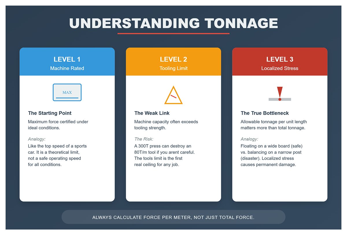
The real “tonnage limit” is not a single number. It is a multi‑layer constraint system that follows the “wooden‑barrel effect”: the overall capacity is determined by its weakest stave.
- Level 1: Machine Rated Tonnage
This is the maximum force the manufacturer certifies under ideal conditions—specifically, when the load is evenly distributed across the full length of the bed. It is an important reference, but only the starting point. Treating it as a universal limit under all conditions is like assuming a sports car can safely run at top speed on any road, in any weather. - Level 2: Tooling Load Limit
This is the critical weak link most frequently overlooked. Your press brake may be capable of 300 tons, but the punch or V‑die you’re using might be rated for only 80 tons per meter. When you perform a high‑tonnage bend over a very short length, the localized load can destroy the tool or permanently deform it—even if the total tonnage is well below the machine’s rating. The tooling is where the force is actually applied; its limit is the first “ceiling” for any job. - Level 3: Load Distribution & Localized Stress
This is the most critical, most dynamic, and ultimately most decisive layer. The effect of the same 100 tons of force spread evenly over 3 meters of material versus concentrated in just 300 mm is dramatically different for the frame and the ram. The latter creates extreme localized stress. It’s like the difference between floating easily on a wide wooden board versus trying to balance on a narrow post in the water—one is stable, the other is a disaster waiting to happen. In practice, the true bottleneck of a press brake is rarely total tonnage; it is allowable tonnage per unit length.
1.2 The Cost of Misjudgment: From Permanent Damage to Safety Incidents
Any time you gamble or miscalculate on tonnage, the consequences are rarely mild. They can escalate into irreversible damage.
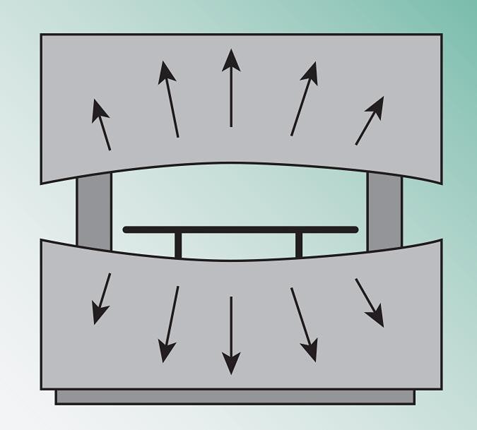
- Permanent Damage to the Machine: “Ram Upset”
Even if an overload doesn’t produce an immediate loud bang, it can still inflict severe “internal injuries” on the press brake. Excessive localized loading causes plastic deformation of the ram and bed—the center section gets pushed down and “sagged.” This damage is cumulative and permanent. Like repeatedly bending a wire, it doesn’t snap right away, but its internal structure is already compromised. Over time your precision press brake effectively becomes a “banana‑shaped” machine with a bowed‑down center, incapable of producing straight parts no matter how you try to compensate. A single serious overload can be enough to write off a machine worth hundreds of thousands. - Sudden Safety Incidents
This is the most immediate and visible cost. When localized stress exceeds the material strength of the tooling, high‑hardness tool steel can shatter like glass, sending fragments flying at high speed and posing a lethal risk to anyone nearby. Overloading can also cause the part to slip or the machine structure to fail—all of which hang over the operator like the sword of Damocles.
1.3 The Value of Precision: From Passive Risk Avoidance to Active Profit Generation
Accurate tonnage calculation is more than a defensive shield against disaster; it is also a proactive management tool that can directly generate profit.
- Direct Gains from Risk Avoidance
The most obvious benefit is avoiding the huge costs of repairs, lengthy downtime, scrap parts, and potential liability claims. A machine that consistently runs within safe tonnage limits will last longer and hold its accuracy far better than expected—and that alone translates into significant cost savings. - Active Profit Creation Through Smart Management
- Process Optimization and Capability Unlocking: With accurate calculations, engineers can confidently choose the smallest feasible V‑die opening for a given product, achieving tighter inside bend radii and shorter straight flanges to meet more demanding design specifications. This not only improves product quality, but can also help you secure high‑end jobs with stringent process requirements.
- Lower Production Costs: Accurate calculation helps you avoid overly conservative process settings. For example, slightly increasing the V‑die opening while staying within safe limits can dramatically reduce the required tonnage, cutting energy consumption and mechanical wear. In high‑volume production, the cumulative savings in energy and maintenance are substantial.
- Rational Investment Decisions: When purchasing new equipment, a precise understanding of current and future tonnage demands allows you to choose the most suitable machine instead of blindly opting for “bigger is better.” This may save hundreds of thousands in upfront investment and free capital for areas with higher returns.
Mastering tonnage limit calculations for press brakes is a key step in transforming from a routine operator or engineer into a specialist who creates core value for the business. It’s not just about technical skill—it’s about responsibility and sound judgment.
II. Core Formula Explained: The Common Language of Tonnage Calculation
In the world of mechanics and forces, formulas are the language that ensures consistency and safety. The calculation of bending tonnage is not based on advanced mathematics, but on a clever application of a classic mechanics model. Once you grasp it, you gain the ability to predict and control a very powerful force.
2.1 One Core Principle: In‑Depth Look at the Air Bending Tonnage Formula
Among all bending methods, air bending stands out for its flexibility and relatively low tonnage requirement, and is therefore the most widely used. Our tonnage calculations will focus on this process. While there are several formula variants in use, they all trace back to the same physics model: three‑point beam bending.
To make the method quick and reliable on the shop floor, the industry generally uses a proven empirical formula:
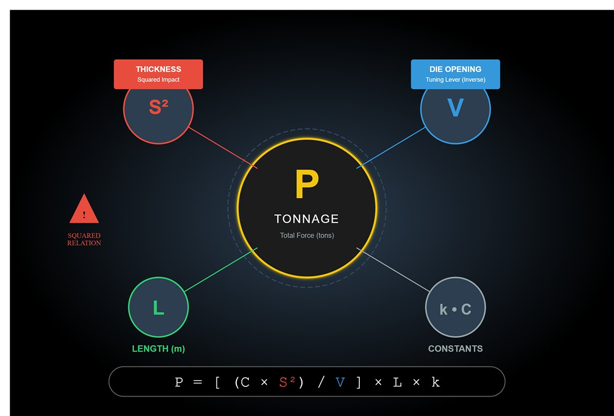
P = [ (C × S²) / V ] × L × k
Let’s break this formula down like a precision instrument, examining each component in turn:
- P (Tonnage): The final quantity we care about—the total tonnage required to complete the bend (unit: tons).
- S (Thickness): The material thickness of the workpiece (unit: mm). Note that it appears as S² (S squared). This means even a small increase in thickness causes the required tonnage to rise sharply. A 4 mm plate needs four times, not twice, the tonnage of a 2 mm plate—this non‑linear rise is one of the most commonly overlooked pitfalls.
- V (V-die Opening): The opening width of the lower die (unit: mm). This is your most powerful tuning lever, and it is inversely proportional to the required tonnage.
- L (Length): The bend line length of the workpiece (unit: m).
- k (Material Factor): The material factor, a dimensionless constant that captures the “personality” of different metals.
- C (Constant): A composite constant, typically taken as about 65 in metric units. It condenses complex strength-of-materials calculations into a single term, making the formula broadly applicable.
The internal logic of this formula is both simple and elegant: bending force is directly proportional to the square of the material thickness, the bend length, and the material’s own strength, and inversely proportional to the support width of the lower die. It’s like trying to snap a wooden stick by hand: the thicker, longer, and tougher the stick, the more force you need; but the farther apart your hands are (analogous to increasing the V value), the easier it is to break.
2.2 Key Variable #1: Material Factor (k) — The Foundation of All Calculations
If the formula is grammar, then the material factor (k) is vocabulary. It converts differences in mechanical properties between materials into a simple multiplier you can plug into calculations. This factor is directly tied to the material’s ultimate tensile strength (UTS).
Industry practice is to use common mild steel as the reference material, with an ultimate tensile strength of about 450 MPa, and to define its k value as 1. The k value of any other material is simply the ratio of its tensile strength to that of mild steel.
Quick Reference: Common Material Factors
| Material Type | Ultimate Tensile Strength (UTS) (approx.) | Material Factor (k) | Notes |
|---|---|---|---|
| Mild Steel | 450 MPa | 1.0 | Baseline for calculations |
| Aluminum (5052-H32) | 225 MPa | 0.5 | Soft, requires very low tonnage |
| Stainless Steel (304) | 600 MPa | 1.3 - 1.5 | Tougher, needs significantly more tonnage than carbon steel |
| High-Strength Steel (e.g., Hardox) | 1250 MPa+ | 2.8+ | Extremely high strength, demands very high tonnage |
Pro Tip: This table is an excellent starting point, but remember that actual material properties vary with heat treatment, supplier, and even batch. For jobs with tight tolerances or expensive materials, always consult the supplier’s Material Test Report (MTR) to obtain accurate tensile strength data and fine-tune your k value.
2.3 Key Variable #2: V-Die Opening (V) — The Golden Lever for Tonnage Control
Among all the variables, the V-die opening (V) is the only one the operator can fully control on-site, and it has a huge impact on the required tonnage. It is your golden lever for adjusting tonnage demand.
- Golden Rule: The 8× Principle
Decades of industry experience have led to a best practice: the V-die opening (V) should be about 6 to 10 times the material thickness (S), with 8× being the most common and well-balanced choice. For example, when bending a 3 mm steel sheet, a 24 mm V-die (3 × 8) is usually an ideal starting point. - The Double-Edged Sword of Changing V
- Reducing V:
- The Appeal: You can achieve a smaller inside bend radius, producing a sharper profile that meets certain design requirements.
- The Cost: The required tonnage rises sharply. From the formula, P is inversely proportional to V. Halving V doubles the tonnage. This is one of the most common ways machines are unknowingly pushed toward overload, and a leading cause of die breakage.
- Increasing V:
- The Advantage: Tonnage demand drops significantly. Bending becomes easier, and stress and wear on both the machine and tooling are greatly reduced.
- The Trade-Off: The inside bend radius increases, and part springback becomes more difficult to control.
Choosing the V value is essentially a trade-off between forming accuracy and machine load. Mastering this trade-off is a key step in progressing from skilled operator to true process engineer.
2.4 Hands-On Exercise: A Step-by-Step Tonnage Calculation
The value of theory lies in its application. Let’s apply the formula to a real production scenario.
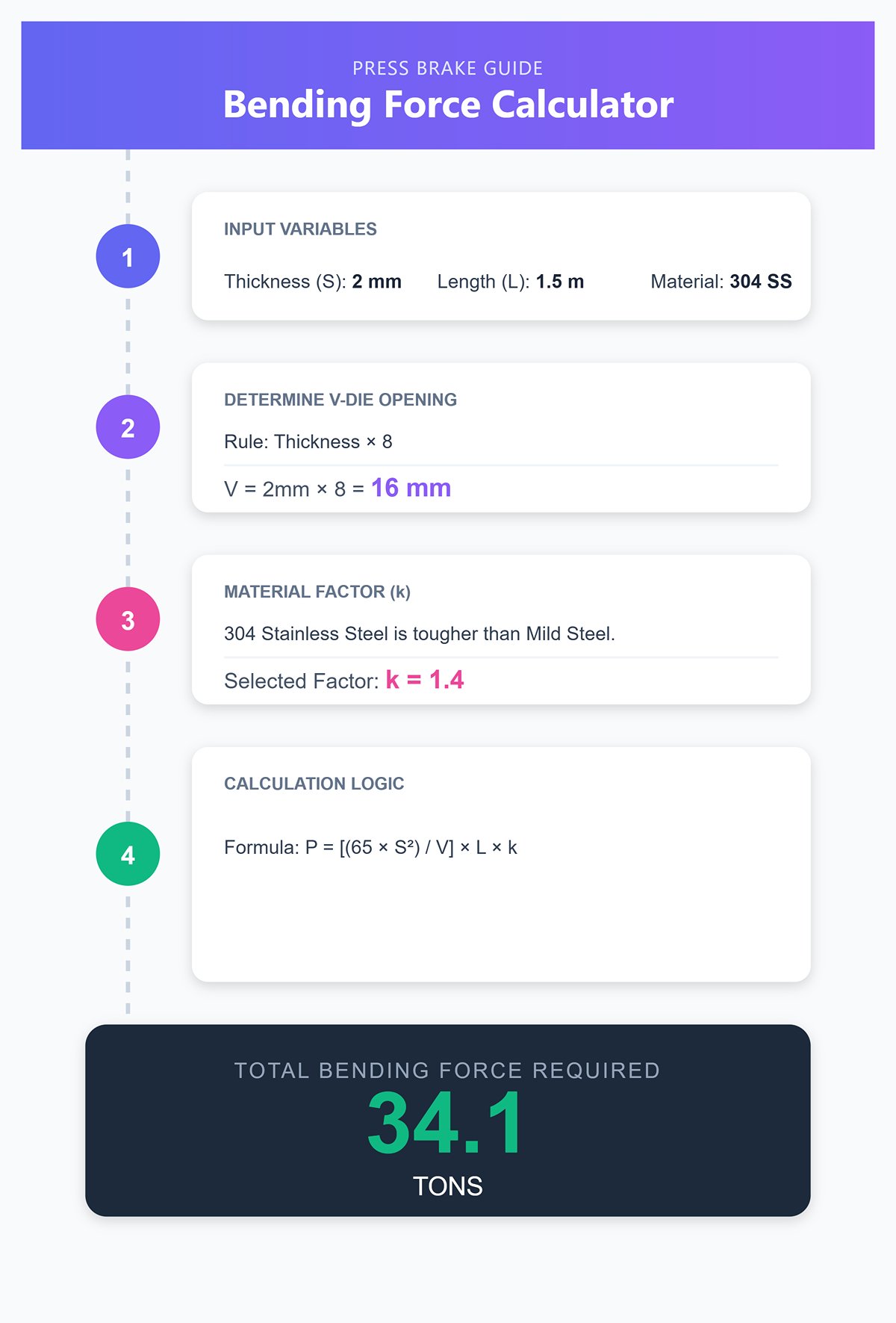
Task: Bend a 2 mm thick (S) 304 stainless steel sheet to 90° along a 1.5 m long (L) bend line.
Step 1: Select the V-Die Opening (V)
- Follow the “8× principle”: V = material thickness (S) × 8 = 2 mm × 8 = 16 mm.
- We decide to use a standard V = 16 mm lower die.
Step 2: Determine the Material Factor (k)
- From the quick reference table above, 304 stainless steel is relatively tough. We select a mid-range value, k ≈ 1.4.
Step 3: Plug Values into the Formula
- Our “universal language” is: P = [ (65 × S²) / V ] × L × k
- Substitute the numbers: P = [ (65 × 2²) / 16 ] × 1.5 × 1.4
- Break it down:
- Inside the brackets: (65 × 4) / 16 = 260 / 16 = 16.25
- Overall: P = 16.25 × 1.5 × 1.4
- Final result: P ≈ 34.1 tons
Interpreting the Result: Theoretically, this bend requires about 34.1 tons of force. If you’re running a 100-ton press brake, this may sound comfortably safe. But this number is only the beginning of the story. It tells you the total force required to complete the bend, but not how that force is distributed across the machine.
If those 34.1 tons are spread evenly over the entire machine, there’s little to worry about. But what if they are concentrated in a very small area? That is exactly what we’ll explore in the next section—and it’s the dividing line between merely operating a press brake and truly understanding it: load distribution and stress concentration, the hidden killers that determine the real lifespan of your machine.
III. From Theory to Reality: Why the Standard Formula Is Only the Starting Point
We’ve just mastered the “common language” of bending tonnage calculation. It tells us, with impressive precision, “how much force is needed to complete this bend.” That’s a major step forward. But if we stop there, we’re making a fatal mistake. Because that number only represents the demand side of the task; we haven’t yet examined the supply side that has to deliver this force—the press brake itself.
Applying the calculated tonnage straight to the machine is like prescribing a drug based solely on how much the illness seems to require, without asking whether the patient’s body can handle that dosage. The leap from theory to reality hinges on one critical insight: the magnitude of the force matters, but the location and distribution of that force are what ultimately determine whether the machine lives or dies.
3.1 Core Insight #1: Distinguish “Ram Force” from “Bed/Ram Capacity”
This is one of the most common misunderstandings in the industry—and the root cause of countless machines “dying young.” Burn these two concepts into your professional intuition:
- Ram Force: This is the “rated tonnage” shown on your machine’s nameplate—the total thrust the hydraulic system can generate. A 200-ton press brake means its “muscles” can, in theory, lift a total of 200 tons. This is the machine’s power source.
- Bed/Ram Capacity: This is the maximum load per unit length that the two key structural members—the ram and the bed—can withstand without permanent deformation. It is typically specified in Tons/meter or Tons/foot. These parts are the machine’s skeleton.
A world-class weightlifter may be able to lift 300 kg—that’s his total strength. But if you make him support that same 300 kg with a single finger, it will shatter instantly. The same logic applies to your press brake: it may have tremendous muscle (ram force), but its skeleton (bed and ram) has very different load-bearing limits at different positions. Structural strength is highest at the center and drops off sharply toward the ends. Confusing muscle strength with skeletal strength is how disasters begin.
3.2 Core Insight #2: Load Distribution—The “Invisible Killer” That Determines Success or Failure
If the total tonnage from your formula is the amount of gunpowder in a bullet, then load distribution is the bullet’s caliber. The same charge in a shotgun shell versus a sniper round will behave—and destroy—in completely different ways. An uneven load, especially off-center loading, is one of the most insidious and destructive enemies a press brake can face.
Imagine two extreme scenarios:
- Ideal condition: You apply 30 tons of force evenly across a 3-meter part, positioned at the exact center of the machine. Each meter sees only 10 tons of pressure, and the machine handles it with ease.
- Dangerous reality: You apply the same 30 tons of force to a short part only 0.3 meters long, clamped to one side of the machine. That tiny 300 mm zone is now subjected to the equivalent of 100 tons per meter—a terrifying stress level.
Here are the situations where this “invisible killer” most often shows up:
- Short-part bending: For convenience, operators habitually bend small parts at one end or one side of the machine.
- Multi-station setups: Multiple tools of different heights and sizes are mounted along the bed to perform several bends at once, creating an extremely unbalanced load.
- Asymmetric bending: The workpiece’s geometric center is offset from the bend line center.
These practices force the hydraulic cylinders on each side of the machine to work under severely unequal loads, generating massive torsional stresses within the ram and bed—like someone trying their best to twist a steel beam in half.
3.3 Core Risk: How Ram Upset Occurs—and How to Prevent It
Repeated or severe off-center loading eventually leads to a final, irreversible outcome—ram upset.
- How it happens: When one cylinder is carrying far more load than the other, the CNC system tries desperately to compensate via servo valves to keep the ram parallel. But this “forced correction” cannot eliminate the underlying imbalance in forces. The resulting huge stresses are transferred into the ram guides, the side frames, and the entire bed structure. Once these stresses exceed the material’s yield strength—even a single time—the metal undergoes permanent plastic deformation. Over time, a small but permanent angle develops between the ram and the bed; they are no longer parallel. At that point, your precision press brake has effectively turned into a “banana machine.”
- Catastrophic consequences:
- Permanent loss of accuracy: You will never again be able to produce parts with matching bend angles at both ends.
- Abnormal tooling wear: Non-parallel contact surfaces will continuously chip and chew away at your expensive punches and dies.
- Premature machine death: Severe ram upset is almost impossible to truly fix. Even if you spend heavily on regrinding and reworking, restoring factory-level precision is extremely unlikely. In practice, it’s equivalent to a death sentence for the machine.
- Ironclad rules for prevention:
- Always work at center: Place bending operations on the machine’s centerline whenever possible.
- Balance the load: If you must work off-center, place a matching tool and workpiece on the opposite side and perform a “counterweight” bend to balance the cylinder loads.
- Respect the limits: Strictly follow the manufacturer’s specifications for off-center loading limits.
3.4 How to Obtain the Real Tonnage Distribution Map for Your Machine
Fortunately, manufacturers have already provided you with a map and a weapon to fight this “invisible killer”—the Tonnage Chart or Load Chart.
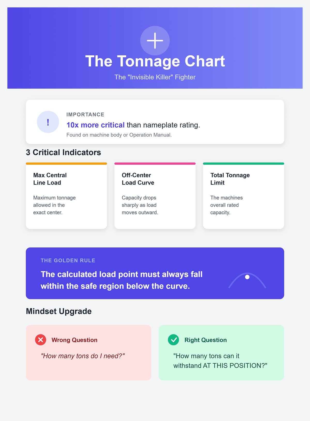
This chart is ten times more important than the single tonnage number on the nameplate. It’s usually posted in a prominent place on the machine or highlighted in the core chapters of the operation manual. If you can’t find it, stop any operation you are unsure about and contact the machine manufacturer immediately. Doing so is part of your responsibility as a professional.
A proper tonnage chart will clearly indicate:
- Maximum central line load: The maximum tonnage per unit length allowed in the central region of the machine.
- Off-center load curve: How the allowable maximum tonnage drops sharply as the load moves away from the machine’s centerline.
- Total tonnage limit: The overall rated capacity of the machine.
When you read this chart, you’ll see a curve that peaks at the machine’s center and plunges steeply toward both ends. That curve is the machine’s lifeline. At all times, the load point you calculate (tonnage vs. position) must fall within the safe region below that curve.
Some advanced press brake controls already include real-time load monitoring and calculation, issuing warnings when you exceed safe limits. But no matter how smart the technology gets, understanding the physical logic behind that chart remains an irreplaceable core skill.
At this point, your mindset should have undergone a key upgrade: instead of asking “How many tons do I need?”, you should be asking “At this exact position, how many tons can my machine safely withstand?” Only after making this shift do you truly hold the key to safe, efficient, and high-precision bending.
IV. Advanced Calculations and Strategies for Complex Bending Conditions
By now, you’ve mastered the “universal language” of tonnage calculation for bending—a solid theoretical foundation for work under ideal conditions. Reality on the shop floor, however, is rarely that tidy. Once your bending tasks move from standard, straight-line parts to irregular, highly complex components, your calculation strategy must evolve as well.
At this stage, tonnage is no longer just a static formula; it becomes a dynamic, system-level management of load distribution, process selection, and tooling variables. This is exactly where a competent operator begins to cross the line into true process mastery.
4.1 Critical Calculations for Short Parts and Localized Loads
Bending short parts is one of the most common—and most underestimated—high‑risk operations in any shop. It introduces a highly dangerous physical phenomenon: concentrated load.
The logic behind this is straightforward and brutal: the total tonnage may not look high, but when it’s applied over a very short length, the pressure per unit length skyrockets. It’s like pressing a sponge with your whole palm versus stabbing it with one finger. The finger causes irreversible damage far more easily because all the force is focused on a tiny area.
Core risk assessment:
- Tool “crush” failure: Enormous localized stress can easily exceed the contact stress limit (Hertzian stress) of the tool steel at the die edge. The result is not gradual wear but micro‑chipping or permanent indentations on the cutting edge—effectively scrapping your expensive precision tooling.
- Hidden damage to bed/ram: This is more serious and irreversible. When the concentrated load exceeds the manufacturer’s specified maximum tonnage per unit length, the ram or bed can undergo permanent plastic deformation. For most standard European (Promecam/Amada‑style) tooling and clamping systems, the limit is around 100 tons per meter. Now imagine you use 30 tons to bend a heavy plate that’s only 200 mm (0.2 m) long. The resulting load is 150 tons/m (30 ÷ 0.2)! Even though the total tonnage is well below the machine’s rated capacity, this single operation is enough to leave a permanent “scar” in your press brake.
Practical countermeasures:
- Treat “tons per meter” as the first commandment: Before any short part or localized load operation, always consult your machine’s tonnage chart. Calculate the actual tons per meter for the job and make sure it stays well within the manufacturer’s safe working curve. This is a hard limit, not a suggestion.
- Invest in heavy‑duty tooling systems: If high‑tonnage localized bending is part of your routine, you must use tooling and clamping systems designed specifically for heavy loads. These typically feature wider shoulders, higher‑grade materials, and optimized stress distribution to withstand far higher unit pressures.
- Actively spread the stress: Where the process allows, avoid repeatedly performing high‑tonnage short bends in exactly the same spot along the ram. Deliberately shifting the working position helps distribute fatigue and wear more evenly, dramatically extending the machine’s high‑precision service life.
4.2 The Art of Load Balancing in Multi-Station and Asymmetric Bending
To maximize throughput, it’s now standard practice to mount multiple sets of tools along the press brake, completing several bends on a part in one pass—so‑called multi‑stage bending. But this gain in efficiency comes at the cost of extreme demands on load balance.
Core risk assessment:
- The number‑one cause of ram upset (ram tilting): This is the primary danger in multi‑station setups. If all high‑tonnage bends are clustered on one side of the machine, or the tonnage requirements between stations differ dramatically, you create severe unbalanced loading. The resulting torque continuously “twists” the machine, eventually causing permanent deformation of the ram and bed.
The art and science of load balancing:
- Core principle: moment balance: Think of your press brake as a precision scale. Your goal is to make the combined center of all bending moments line up with the machine’s mechanical and hydraulic centerline. The basic equation is: Force₁ × Distance₁ = Force₂ × Distance₂.
- Symmetrical layout method: This is the simplest and most elegant approach. Wherever possible, place bending operations with similar tonnage requirements symmetrically on both sides of the machine centerline.
- Counterweight method: If true symmetry isn’t possible, you can add a “dummy” station on the lighter side with an extra tool and bend a scrap piece (or perform a simulated bend). The tonnage at this station should roughly match the asymmetric load on the opposite side, acting as a counterweight to balance the system.
- Leverage your CNC: Advanced CNC press brakes often include built‑in off‑center load calculation and alarm functions. By entering the tonnage and position of each station during programming, the control can automatically verify whether the total moment exceeds safe limits, giving you a highly reliable safety net.
4.3 Tonnage Differences Between Bending Methods
All of the formulas we analyzed earlier assumed one specific process: air bending. Once you switch to a different forming method, the tonnage requirements change dramatically. If we treat the tonnage for air bending as the baseline “1x,” the relative forces required for other methods are often eye‑opening.
| Bending Method | Core Description | Relative Tonnage Demand | Professional Insight |
|---|---|---|---|
| Air Bending | The punch drives the sheet into the V-die without fully bottoming out. The angle is controlled precisely by the punch stroke depth (Y-axis). | 1x (baseline) | The most common, flexible, and energy-efficient method. This is the dominant process for modern CNC press brakes. |
| Bottom Bending | The punch pushes the sheet further down against the die shoulders, using the die angle itself to “set” the bend angle and overcome springback. | Approx. 3x–5x | Provides better angle consistency than air bending, but requires much higher tonnage and extremely accurate die angles. |
| Coining | The punch applies a very high force to press the sheet fully into the bottom of the die, thinning the material in the bend zone and physically eliminating springback. | Approx. 5x–10x (or even higher) | Delivers exceptional angle accuracy, but the enormous tonnage causes severe wear on both machine and tooling. It has been largely phased out in most applications. |
Key takeaway: Choosing a bending method is not just a technical decision—it’s a strategic choice about what magnitude of force you are going to impose on your equipment. Switching from air bending to bottom bending without precisely recalculating tonnage is one of the most common beginner mistakes, and it is more than enough to damage a machine.
4.4 The Hidden Impact of Special Tools and Accessories
Finally, don’t overlook any of the “small accessories” you mount on the ram or bed. Each one can become a hidden variable that significantly alters the tonnage required for the job.
- Wing dies: These lower dies have rotatable “wings” on both sides that protect the material surface during bending, making them ideal for aluminum, stainless steel, or pre‑painted sheets. However, their unique mechanical structure increases friction and shifts the leverage point, so the required tonnage is typically 20% to 50% higher than with a standard V‑die.
- Flattening / hemming tools: This process usually has two stages: first, a sharp bend of about 30° is formed using an acute die; then a flat tool is used to close it into a hem. The tonnage requirement for the second, flattening step is extremely high because there is almost no effective lever arm—the machine is relying on near‑pure brute force to compress two layers of metal into a tight hem.
- Urethane pads / films: Placing a urethane pad on top of the lower die, or applying a protective film on the sheet surface, is an effective way to prevent die marks. But these elastic materials act like a sponge and absorb part of the bending energy. This means you must increase tonnage appropriately (typically by about 10–15%) to compensate for the energy loss and still achieve the desired bend angle.
In summary, advanced tonnage management is an art. It requires you to think beyond a single formula and build a panoramic mechanical model in your mind. Every decision—from where you place the workpiece, to which process you select, to how you combine tools—continuously reshapes the “conversation of forces” between you and this powerful machine.
V. Pitfall Guide and Best Practices
Transforming all the deep theoretical knowledge from the previous chapters into every safe, precise bend on the shop floor is blocked by the widest chasm of all: human habit and human neglect. Theory is the map; practice is marching through a battlefield laced with hidden mines.
This chapter aims to give you a detailed mine‑clearing chart and a complete operating system that allows your team to cross this minefield safely. It is not only about avoiding risk; it is about forging your professional know‑how into a core competitive advantage for your business.
5.1 Seven Deadly Calculation Errors and How to Avoid Them
In real‑world tonnage calculation and application, countless cases of equipment damage and safety incidents can be traced back to repeatedly committing a few fundamental mistakes. These errors are like submerged reefs, fully capable of capsizing even the sturdiest vessel. Below are the “seven deadly errors” that must be identified and eliminated with the highest level of vigilance.
Material “identity fraud”: treating stainless steel like a docile sheep
- Typical mistake: Operators habitually use low‑carbon steel parameters to calculate tonnage for stainless steel or high‑strength steel, or they overlook the huge strength differences between various aluminum alloys.
- Fatal consequence: The calculated tonnage may be only half, or even one‑third, of what is actually required. The hydraulic system ends up howling in pain under loads far beyond what was expected, parts fail to form, and in more serious cases, the massive reaction forces directly impact the hydraulic valve group and mechanical structure, causing “internal injuries.”
- Avoidance strategy: Build a tamper‑proof “material gene bank.” In the CNC controller or MES system, create a dedicated profile for every commonly used material, including its exact tensile strength and material factor (k). The operator’s job is not to key in numbers, but to select the material grade from a menu. The system then automatically calls up the correct parameters, eliminating identity fraud at the source.
The V‑opening “temptation trap”: risking the die’s life for a sharp radius
- Typical mistake: To obtain an extremely small inside bend radius, engineers or operators, based purely on experience, choose a V‑die width far below the “8× material thickness” golden rule.
- Fatal consequence: The required tonnage skyrockets. This geometrically amplified force quickly exceeds the contact stress limit at the die edge, leading to chipping or permanent damage. This is one of the most common “die killers” on the shop floor.
- Avoidance strategy: Standardize the golden rule and impose authorization thresholds. Set “V‑opening = 8 × material thickness” as the default system recommendation. Any V‑opening below 6× material thickness must trigger a secondary warning prompt and even require supervisor password authorization. Post a simple visual chart showing how V‑opening affects tonnage right next to the tonnage chart so operators can literally see the risk.
The “silent switch” of process: the deadly jump from air bending to bottoming
- Typical mistake: In the program, the bending method is changed from air bending to bottoming without accounting for the fact that tonnage demand will jump by a factor of 3 to 5.
- Fatal consequence: This is the most insidious kind of “murder” of a machine. While the operator remains unaware, the press brake is subjected to a terrifying load several times higher than the calculated value. A single operation can leave permanent plastic deformation in the ram and bed, turning your precision machine into a “banana press.”
- Avoidance strategy: Implement “smart process alarms” in the control system. When “bottoming” or “coining” is selected in the CNC program, the system must automatically multiply the calculated tonnage by the appropriate safety factor and highlight the final estimated tonnage in bright red. If the value exceeds the safe limit, the program must be locked and prevented from running.
The “boiling frog” of off‑center loading: always favoring one side
- Typical mistake: For convenience, short parts are routinely bent at one end of the machine; or when setting up multiple stations, high‑tonnage operations are grouped on one side.
- Fatal consequence: Continuous asymmetric loading acts like an invisible giant, twisting your machine day after day. Over time, the ram and bed are no longer parallel—this is “ram upset.” Accuracy is lost for good, and the machine reaches the end of its life prematurely.
- Avoidance strategy: Introduce “load‑center visualization.” A good CNC system can calculate and display the combined “load center” of all stations in real time. SOPs must stipulate that the offset between this center and the physical center of the machine must not exceed 10%. Where off‑center loading cannot be avoided, it must be counterbalanced by placing equivalent tooling and scrap on the opposite side to act as a “counterweight.”
The “single‑point blast” of pressure: focusing only on total force, not pressure density
- Typical mistake: When bending a short, thick part, the calculated total tonnage (e.g., 30 tons) is far below the machine’s rated capacity (e.g., 100 tons), so everyone assumes they are perfectly safe.
- Fatal consequence: What they ignore is that when 30 tons are applied over a length of just 200 mm, the line load is already 150 tons/m—far beyond the 100 tons/m limit of standard tooling and the bed. This leaves a permanent “dent” at the die edge and on the table surface.
- Avoidance strategy: Enforce a dual check on total tonnage and tons per meter. Treat “load per unit length” as just as critical as total tonnage. During programming and operation, both values must be calculated and verified to be within safe limits.
Blind faith in the nameplate rating: believing in a “universal promise”
- Typical mistake: Assuming that a 200‑ton press brake can safely deliver 200 tons of force at any position along the bed.
- How to avoid it: Treat the “tonnage distribution chart” as your ultimate operating guideline. Print this critical chart at the largest, clearest size possible and post it in the most visible spot on the machine. Provide dedicated training for all relevant personnel so they can read and follow this “lifeline chart” as instinctively as they read traffic lights.
Temperature: the “invisible variable” – ignoring steel’s “winter mood”
- Typical mistake: In cold winter conditions, feeding steel plates straight from the freezing outdoors into the press brake for bending.
- Disastrous consequence: Metal becomes brittle at low temperatures (“cold brittleness”): toughness drops sharply, while yield strength and tensile strength increase. This means the tonnage required to achieve the same bend can unexpectedly rise (by up to 20%), and the risk of the material cracking right at the bend line increases dramatically.
- How to avoid it: Establish a “material warm-up” SOP. Your company procedures should clearly state that, especially when ambient temperature is below 10°C, all metal plates must be left in the workshop (around 20°C) long enough (at least 2–4 hours) for their core temperature to equalize with the environment before any processing is allowed.
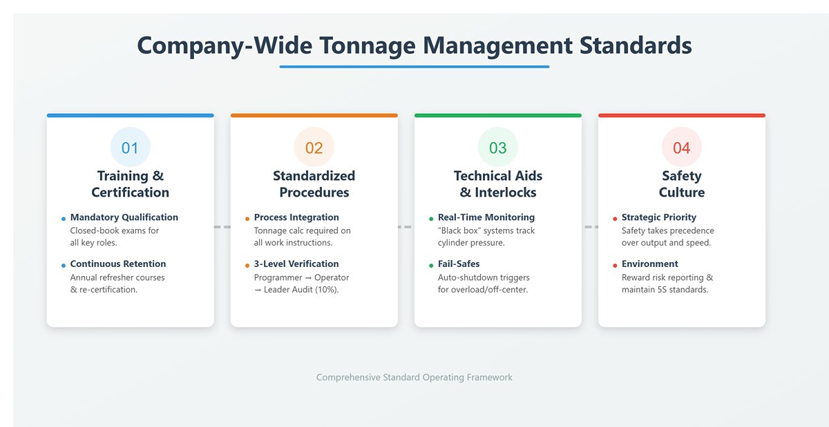
5.2 Establishing company-wide tonnage management standards
Individual skill and vigilance are fragile. Only by turning best practices into company-wide rules can you build an unbreakable line of defense. This calls for a comprehensive framework that spans awareness, behavior, and culture.
- Step 1: Mandatory training and certification – building a fully qualified professional team All press brake operators, programmers, and even workshop supervisors must complete mandatory training and closed-book exams on tonnage calculation, load management, and safe operation, and obtain a “work qualification” certificate. The training must cover 100% of the theory above and all “seven deadly mistakes.” Conduct annual refresher courses and re-certification to lock this knowledge into muscle memory.
- Step 2: Standardized operating procedures (SOPs) – eliminating uncertainty with process Make tonnage calculation and load verification mandatory fields on every process card or work instruction. Implement a “three-level verification” system: the programmer calculates and notes tonnage in the program → the operator double-checks and signs off before production → the team leader randomly audits at least 10% of jobs each day. This workflow functions like a pilot’s pre-flight checklist—the final safeguard that ensures nothing is left to chance.
- Step 3: Technical aids and mandatory interlocks – turning the machine into a “fault-proof supervisor” Invest in and fully deploy a modern real-time tonnage monitoring system. These systems act like an onboard “black box” and “bodyguard” for your equipment, continuously monitoring the pressure in both cylinders. If total tonnage exceeds the limit or the pressure difference between the two sides becomes excessive (severe off-center loading), they trigger immediate audible and visual alarms and can even force an automatic shutdown. This is the most effective “fuse” against catastrophic human error.
- Step 4: Building a safety culture – making respect for risk your primary productivity driver Elevate safety to a strategic priority on par with, or above, quality and efficiency. Publicly reward employees who proactively report potential tonnage risks or propose process improvements. Senior management must consistently emphasize, and personally demonstrate, that safety always takes precedence over output. A clean, orderly 5S workplace is the most visible expression of a strong safety culture and fundamentally reduces errors caused by chaos.
By progressing through these four steps, your company can build a complete tonnage management system that spans individual awareness (training), team behavior (SOPs), technical safeguards (monitoring systems), and organizational climate (safety culture). At that point, the press brake’s tonnage limit is no longer a vague red line, but a fortress of safety built from knowledge, process, and technology—solid and unshakable.
VI. Conclusion
Mastering tonnage calculation is a core discipline. It demands moving beyond a machine's rating to account for tooling, materials, and load distribution. Understanding these principles is the foundation of a safe, efficient, and profitable shop, especially when you are configuring or upgrading key equipment such as a modern press brake.
Knowledge is the first step; implementation is the next. ADH Machine Tool provides complete bending solutions, not just machines. Our experts will help you select the right equipment and train your team for precision and safety, ensuring your shop gets maximum value from every bend and every ton of capacity.
Contact us at ADH today to turn your bending operations into a competitive advantage.


