Mastering how to callout bend angles for using press brake is the critical first step to eliminating scrapped parts and production delays in sheet metal fabrication. A seemingly minor error in an angle callout creates a communication gap between design intent and shop floor reality, often leading to costly failures.
This definitive guide bridges that gap. We will deconstruct the entire process, providing a systemic framework for creating "zero-inquiry" drawings. From the physics of springback to advanced GD&T and the final quality checks, you will learn the language of bending to ensure that what you design is exactly what you get.
I. Core Cognition Module: Rebuilding Your Conceptual Framework for “Bend Angle”
Before diving into complex formulas and CNC programming, you have to tackle a fundamental misconception: the bend angle is far more than a simple geometric value. It is the physical outcome of the combined influence of material mechanics, machine characteristics, and tooling geometry. Reshaping this understanding is the prerequisite for truly achieving “what you see is what you get” precision manufacturing.
1.1 Hitting the Pain Point: Why Angle Callouts Quietly Destroy Your Yield Rate
In sheet metal fabrication, an uncomfortable truth is this: 80% of assembly issues can be traced back to 20% of bend-angle deviations. Many engineers casually put a simple “90°” on the drawing and overlook the process abyss hidden behind that number.
Inaccurate or ambiguous angle callouts come with strong latency and amplification effects. A ±0.5° deviation that appears “within spec” during single-part inspection rarely raises alarms. But once that part reaches the welding fixture or final assembly, accumulated tolerances can cause misaligned holes, enclosures that won’t close, or even destructive residual stresses. At that stage, the cost of fixing the problem is no longer a few scrapped blanks, but line stoppages and expensive rework across the entire production flow.
The real silent killer is not the operator’s “shaky hands”, but the disconnect between design language and manufacturing language. When factors like material anisotropy, batch-to-batch hardness variation, and machine wear are ignored, a static drawing angle cannot reliably guide a dynamic bending process. If the callout doesn’t clearly distinguish between “design angle” and “formed angle”, and if it fails to account for springback, rising scrap rates are not just likely—they’re structurally inevitable.
1.2 Unified Definitions: Creating an Unambiguous Language Standard
Precision manufacturing starts with precise definitions. To eliminate the communication gap between design (CAD) and manufacturing (CAM/shop floor), you need a standardized terminology system. Moving from vague descriptions (“bend it a bit”, “roughly a right angle”) to quantified engineering language is a non‑negotiable step.
Here are the core terms that must be strictly distinguished:
| Term | Definition | Engineering Significance |
|---|---|---|
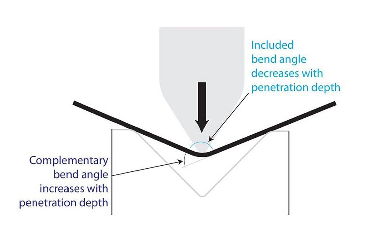
| Included Angle | The angle between the inner faces of two flanges. | Design reference. This is usually the angle the designer intends to specify on the drawing (e.g., 90°). |
| Supplement Angle | 180° minus the included angle. | Machine reference. Press brake controllers typically calculate ram depth based on this angle, which is the angle at which plastic deformation actually occurs. |
| Bend Radius | The inside arc radius of the bend (IR). | Stress hotspot. Smaller is not always better; too small a radius can cause cracking on the outer surface, while too large a radius makes springback difficult to control. |
| Bend Line | The line on the flat pattern that indicates where the bend occurs. | Location reference. It is the only coordinate “lock” that links the 2D flat pattern to the 3D formed part and directly determines backgauge positioning. |
Expert Tip: On the drawing, you must explicitly state whether the specified angle is an included (inside) angle or an outside angle. Industry best practice is: unless otherwise noted, drawing angles are interpreted as included angles, while angles in CNC programs must be converted according to the logic of the press brake control.
1.3 Key Terms and Parameter Breakdown
To achieve robust, error‑proof angle callouts, you cannot stop at geometry. You need to understand the three physical parameters that govern formed quality. They are the bridge between the idealized model and what actually happens on the shop floor.
A. Springback: The Inescapable Law of Physics
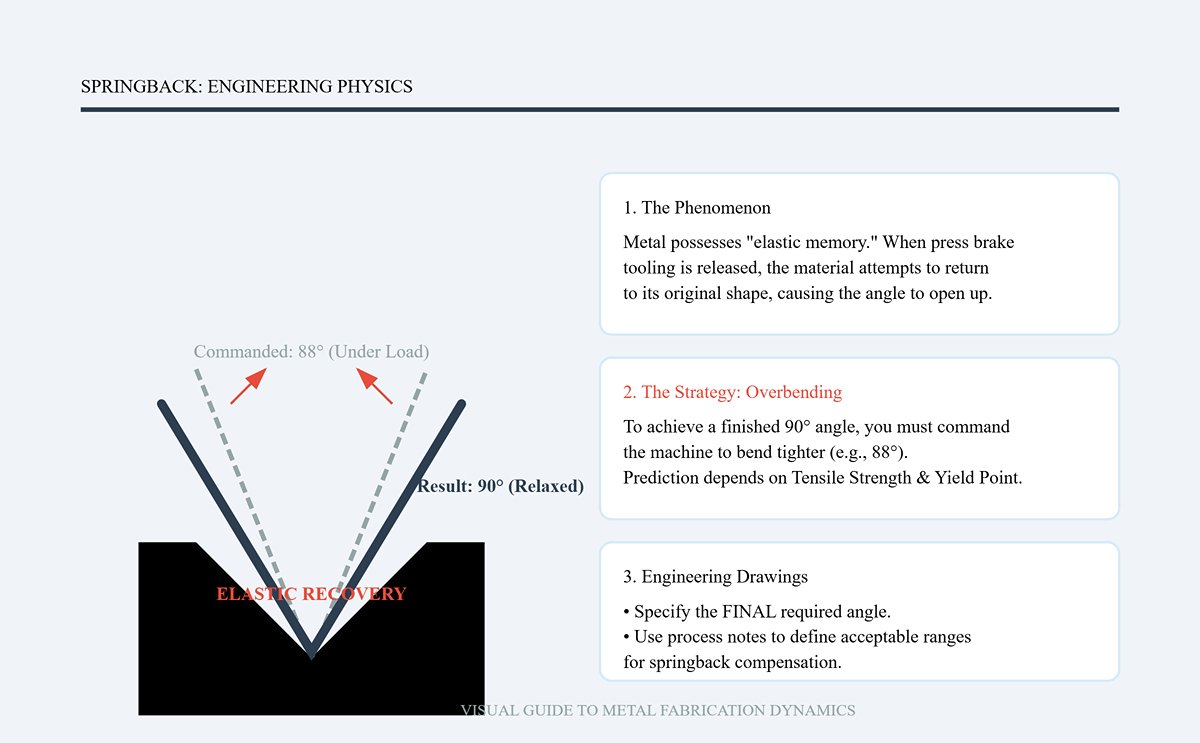
Metal has elastic memory. When the tooling on the press brake is released, the material attempts to return to its original state, causing the actual angle to “open up” a few degrees compared with the tool angle.
- Implication for callouts: If you want a finished angle of 90°, you must “command” the machine to bend to 88° or even tighter. This overbending has to be predicted based on material properties such as tensile strength and yield point. On the drawing, you still specify the final required angle, but your process notes should define acceptable ranges or allowances for springback compensation.
B. K-Factor: The Soul of Flat-Pattern Calculation
The K‑factor is the most critical—and most frequently misused—parameter in sheet metal bending. It defines the relative position of the neutral axis (the layer that is neither in tension nor compression) within the material thickness ($K = t/T$).
- Why it affects the angle: Although the K‑factor is primarily used to calculate flat‑pattern length, it directly relates to how material flows in the bend region. An incorrect K‑factor produces flats that are too long or too short. When blank length is wrong, operators are forced to “fix” things by tweaking bend angles or backgauge positions to make edges line up. The result: the measured angle may look perfect, but the critical functional dimension—the flange length—is now out of spec.
C. Bend Deduction (BD) and Bend Allowance (BA)
These are the mathematical tools that translate a 3D design into a 2D cutting layout.
- BA: The arc length of the neutral axis within the bend region.
- BD: The total “stretch” caused by bending—i.e., the value that must be subtracted from the sum of flange lengths to obtain the correct flat length.
- Practical impact: When defining bend angles on your drawing, you must ensure that your flat‑pattern calculation method (BA or BD) is consistent with the actual tooling used on the floor (V‑die width, punch radius, etc.). If your BD value was derived assuming an R2 die, but production uses an R5 die, then even a bend angle controlled to within 0.1° will still produce scrap parts.
In summary: A correct angle callout is not just a number. It is the result of a holistic evaluation of springback, neutral axis shift, and tooling compatibility. Only after mastering these fundamentals can we move on, in the next section, to creating engineering drawings with standardized bend callouts that require zero clarification from the shop.
II. Engineering Callout Module: How to Produce a “Zero‑Inquiry” Drawing
The true value of a well‑designed sheet metal drawing lies not in how pretty the lines look, but in how losslessly it transmits information. It must not only tell manufacturing what to make, but also define clearly how it will be accepted, eliminating the “information entropy” between design intent and production reality.
The objective is to output a Zero‑Inquiry drawing—one that allows the operator to start programming and producing conforming parts immediately, with no phone calls to confirm dimensions and no guessing about tolerance intent.
2.1 Standardized Callout Strategy (Callout Standards)
To achieve this goal, the drawing must be elevated from a “reference document” to a “contractual specification.” The following three core strategies are key to eliminating ambiguity and ensuring accurate information transfer:
1. Three-in-One Views: Building a Self-Consistent Geometric Definition
Traditional drawings often rely on a single view, but for precision sheet metal you need a robust “data triangle”:
- Formed View — the only acceptance criterion: This is the soul of the drawing. All critical functional dimensions of the final formed part must be clearly defined here. When there is a conflict between formed dimensions and flat pattern calculations, the formed view always takes precedence.
- Flat Pattern — for reference only: This is a common trap. Different shops use different press brake tooling, material batches, and K-factor settings, so theoretical flat lengths will inevitably vary. Do not use flat pattern dimensions as mandatory inspection criteria. Best practice is to add a prominent note on the drawing: “FLAT PATTERN FOR REFERENCE ONLY - VENDOR TO ADJUST FOR K-FACTOR” (flat pattern for reference only; supplier must adjust based on their own K-factor).
- 3D Model (STEP/IGES) — geometric source of truth: Supplying a revision-controlled 3D model is now standard practice. It allows CAM engineers to extract geometry directly for bend simulations and serves as the ultimate arbiter when disputes arise over complex, non-standard bend shapes.
2. The Golden Rule of Dimensioning: Lock to the “Virtual Intersection”
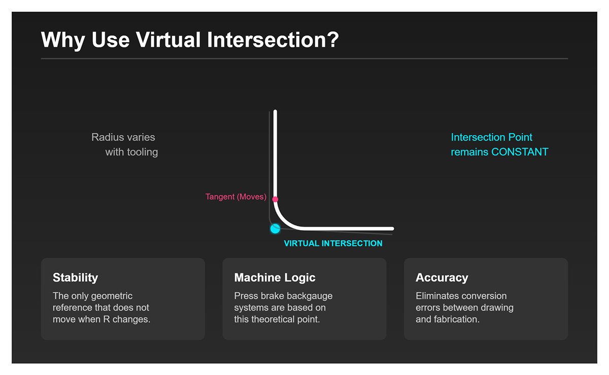
In bend dimensioning, beginners often make the mistake of dimensioning to the tangent point of the bend radius. This is a “floating” reference, because the actual radius is influenced by tooling and can vary, causing the tangent point to shift.
- Virtual Intersection Dimensioning: Always dimension to the theoretical intersection of the two flange planes (the sharp corner extension).
- Why do this? The virtual intersection is the only geometric reference that does not move when the bend radius (R) changes. The press brake backgauge system is also based on this concept. By dimensioning to the virtual intersection, you align your drawing directly with the machine’s control logic and eliminate conversion errors.
3. Information Completeness Checklist
A “Zero-Inquiry” drawing must explicitly define the following hidden parameters and refuse any reliance on “default” assumptions:
- Precisely defined material: Avoid vague descriptions like “stainless steel.” You must specify down to “SS 304 2B Finish” or “AL 5052-H32.” Different tempers directly affect springback and bend factors.
- Inside vs. outside angle declaration: Clearly state in the title block or notes: “All Bend Angles are +/- 1 deg and are INSIDE angles unless otherwise noted.” This eliminates confusion over which side of the bend the angle refers to.
- Grain and burr direction: For parts with brushed finishes or specific surface treatments, use arrows to indicate grain direction and specify whether the burr should be on the inside or outside of the bend. This directly affects fatigue life and assembly safety.
2.2 Applying GD&T to Sheet Metal Bending
GD&T is a universal language, but in sheet metal its use is often described as a “flexible art.” Simply copying rigid machining tolerances onto sheet metal parts will only drive up costs and create large quantities of “false scrap.”
Shifting from “Rigid Thinking” to “Flexible Thinking”
By nature, sheet metal parts are non-rigid. They may warp or twist in a free state but return to the intended shape once bolted or clamped in their installed condition.
- Restrained-condition dimensions: For large flat areas or long flanges, you must add a note such as: “Dimensions apply in restrained condition.” This allows inspectors to use fixtures that simulate the final assembly state when measuring, avoiding false nonconformances caused by gravity or residual stress.
Core Tools: Profile and Datums
- Profile of a surface: This is the most powerful tool for controlling complex sheet metal bends. It defines a tolerance zone enveloping the theoretical surface. Compared with simple angle tolerances, profile control can simultaneously manage angular deviation, flatness, and positional accuracy, while giving manufacturing reasonable room for process adjustments.
- Functional datum selection: Datum features must be chosen based on the actual assembly conditions of the part.
- Poor practice: Using a small, free-hanging edge as Datum A.
- Good practice: Using the plane containing the mounting holes, or the flange with the largest contact area to the mating part, as Datum A. This ensures that the resulting tolerances directly support real-world assembly requirements.
Pitfall Avoidance Guide
- Use flatness sparingly: Avoid extremely tight flatness requirements (e.g., 0.1 mm) on large, thin sheet metal surfaces. The “oil canning” effect is practically unavoidable in sheet metal and makes such specs both difficult to meet and of little practical value. In most cases, controlling the relative position of mounting points is far more meaningful than controlling the flatness of the entire surface.
2.3 Annotation in the Digital Era: Moving Toward MBD
With the advance of Industry 4.0, traditional 2D drawings are gradually giving way to Model-Based Definition (MBD). This is not just a change in file format; it represents a generational shift in how we think about annotation and definition.
Single Source of Truth
Under the ASME Y14.41 framework, MBD attaches PMI (Product Manufacturing Information) directly to the 3D model.
- Eliminating “translation” errors: In the traditional workflow, programmers must mentally reconstruct a 3D shape from a 2D drawing and then input it into the press brake controller. With MBD, press brake software (such as Metamation or AutoPOL) can read STEP/AP242 files containing PMI directly, automatically extracting bend angles, flange lengths, and tolerance requirements. This can reduce programming time from hours to minutes.
Practical Advice: Hybrid Strategies During Transition
If your supply chain is not yet fully ready for end-to-end MBD, adopt the following transitional strategies to improve efficiency:
- Strong revision linkage: Clearly state on the PDF drawing: “Part geometry is defined by 3D Model file: [Filename_Rev_B.stp].” This establishes the 3D model as the geometric authority, with the 2D drawing serving as a supplement for tolerances and process notes.
- 3D definition of critical dimensions: Start marking key control dimensions (Key Characteristics) directly in your 3D CAD software and export them as 3D PDFs for the shop floor. This helps operators clearly see which areas are “untouchable” critical zones and which areas are more forgiving, where minor variation is acceptable.
By implementing the above standards and strategies, we transform “bending angle” from a single number into a rigorous engineering instruction system. This is not just an upgrade in drawing quality; it is also the greatest form of respect for downstream manufacturing. Next, we will dive into the physical mechanisms behind these annotations—springback compensation and process calculation.
III. Principle & Mechanism Module: Core Logic of Springback Compensation and Process Calculation
If engineering annotations are the “constitution” of bending processes, then springback is the “rebel” constantly trying to challenge that constitution. The moment the press brake ram moves down, we are not just changing geometry; we are engaging in a complex mechanical contest with the material’s internal microstructure. A deep understanding of this physics is the watershed between trial-and-error and right-the-first-time forming.
3.1 The Physical Essence of Springback
To control bend angle precisely, we must first abandon the false intuition that “metal behaves like modeling clay.” Sheet metal is both plastic and elastic; the bending process is actually a combination of plastic deformation (permanent shaping) and elastic deformation (attempting to recover).
The “civil war” model of internal stress When the press brake tooling applies force, the sheet cross-section undergoes intense stress differentiation:
- Inside (compression zone): Material is compressed and the distance between atoms decreases.
- Outside (tension zone): Material is stretched and the distance between atoms increases.
- Neutral axis: A transition layer that is neither in tension nor in compression.
The crux of the problem is that although the outer and inner layers exceed the material’s yield strength and undergo plastic deformation, the region near the neutral axis experiences lower stress and remains in the elastic range. When the tooling unloads, this elastically bent region tries to return to its original shape, releasing energy like a spring and driving the entire part to rebound in the opposite direction.
Two decisive variables:
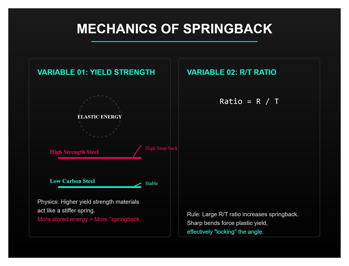
- Ratio of yield strength to modulus: Materials with higher yield strength (such as high-strength steels) store more elastic energy and therefore exhibit more severe springback. This is why bending stainless steel to the same thickness requires more overbending than low-carbon steel.
- R/T ratio (bend radius / sheet thickness): This is a frequently overlooked, counterintuitive rule: the larger the R/T ratio, the more pronounced the springback. A large bend radius means lower strain per unit area, so a smaller portion of the material yields plastically and elastic deformation dominates. In contrast, a sharp bend (small R) forces more material into plastic yield, effectively “locking in” the angle.
3.2 Calculating and Back-Calculating Angle Compensation
Since springback is a law of physics, our strategy should shift from “eliminating springback” to “controlling springback.” The core logic is straightforward: to achieve a drawing angle of $90^{\circ}$, the machine must be commanded to go to $88^{\circ}$ (or even less). This is the art of overbending.
Reframing the calculation logic In process calculations, we focus on two core formulas:
Angle compensation formula:
where
is the tooling/machine target angle
is the final part angle, and
is the springback angle. Note: the minus sign depends on how you define your coordinate system; the essence is “bend deeper.”
Springback factor (Ks) and radius growth: Springback affects not only the angle but also increases the bend radius.
This means that if you use an R5 punch in air bending, the actual inside radius after springback may become R5.2 or even larger. This radius change, in turn, influences how you select the K-factor for flat pattern calculation.
From experience-based to data-driven Generic formulas for springback often result in errors of 1°–2°.
Top-tier shops build a company-wide material database:
- They log actual springback values for different materials (SS304, AL5052), thicknesses, and grain directions under specific tooling setups (V-opening, etc.).
- Practical tip: When drafting process sheets, don’t just write “bend to 90°.” Instead, specify “target 90°, machine setting 88.5° (for reference).” This gives operators a clear starting point for fine-tuning.
3.3 Compensation Strategies for Complex Scenarios
In non-standard conditions, simple linear compensation often breaks down, and more advanced process strategies are required.
A. Anisotropy from grain direction During rolling, sheet metals develop a distinct grain structure.
- Bending transverse to grain: The material resists cracking better, but springback is larger.
- Bending parallel to grain: More prone to cracking on the outside of the bend, but springback is smaller.
- Strategy: During nesting, keep the grain direction consistent for critical bent parts whenever possible. If mixed orientations are unavoidable, you must assign different angle compensation values in the CNC program for parts with different grain directions.
B. Air bending vs. coining
- Air bending: Controls the angle by controlling punch depth. It is the most flexible method but also the most sensitive to springback, so it relies heavily on accurate compensation algorithms (such as modern press brakes with angle-measurement systems).
- Bottoming/Coining: When ultra-high accuracy is needed and springback is hard to control, this method can be used. By applying very high tonnage (typically 5–8 times that of air bending), it compresses the material thickness and destroys the neutral axis’s elastic memory.
- Trade-offs: Faster tool wear, higher-tonnage machines required, and you're constrained to specific die angles (for example, a $90^{\circ}$ die can practically only produce a $90^{\circ}$ bend).
C. The trap of large-radius “bump bending” For large-arc bends, if you use bump bending (approximating a large radius with many small incremental bends using a standard die), springback effects will accumulate across all those steps.
- Strategy: When calculating, you need to distribute the total springback across each incremental bend. For example, if you split a 90° large-radius bend into 30 steps, the programmed angle for each bend should not simply be 3°. It may need to be 3.1° per step instead.
By mastering these principles, we evolve bending from a “feel-based craft” into a precise, computable, and predictable science. Next, we’ll take these calculated core parameters to the shop floor and see how to implement them on the CNC controller for real-world production.
IV. On‑Site Execution Module: From Drawing to CNC Controller Implementation
This is where theoretical models collide head‑on with physical reality. No matter how beautiful the engineering drawing is, if it cannot be correctly translated into the press brake’s control logic, it is ultimately meaningless. In this module, we’ll uncover the final—and most critical—last mile from “design intent” to “conforming part.”
4.1 Translating Into the Press Brake Control System’s Language
Modern CNC press brakes are no longer just hydraulic machines executing mechanical motions; in essence, they are industrial computers with built‑in physics engines. The “90° inside angle” labeled on the drawing must undergo a crucial language conversion the moment it enters the machine controller: it must be transformed from “geometric language” into “axis control language.”
The functional relationship between depth (Y‑axis) and angle In air bending—which today accounts for more than 90% of all applications—the machine does not directly “make” an angle. Instead, it controls the ram’s downward depth (Y‑axis position) to “induce” the material to form. The controller performs real‑time calculations based on the following relationship:
How callouts directly affect programming
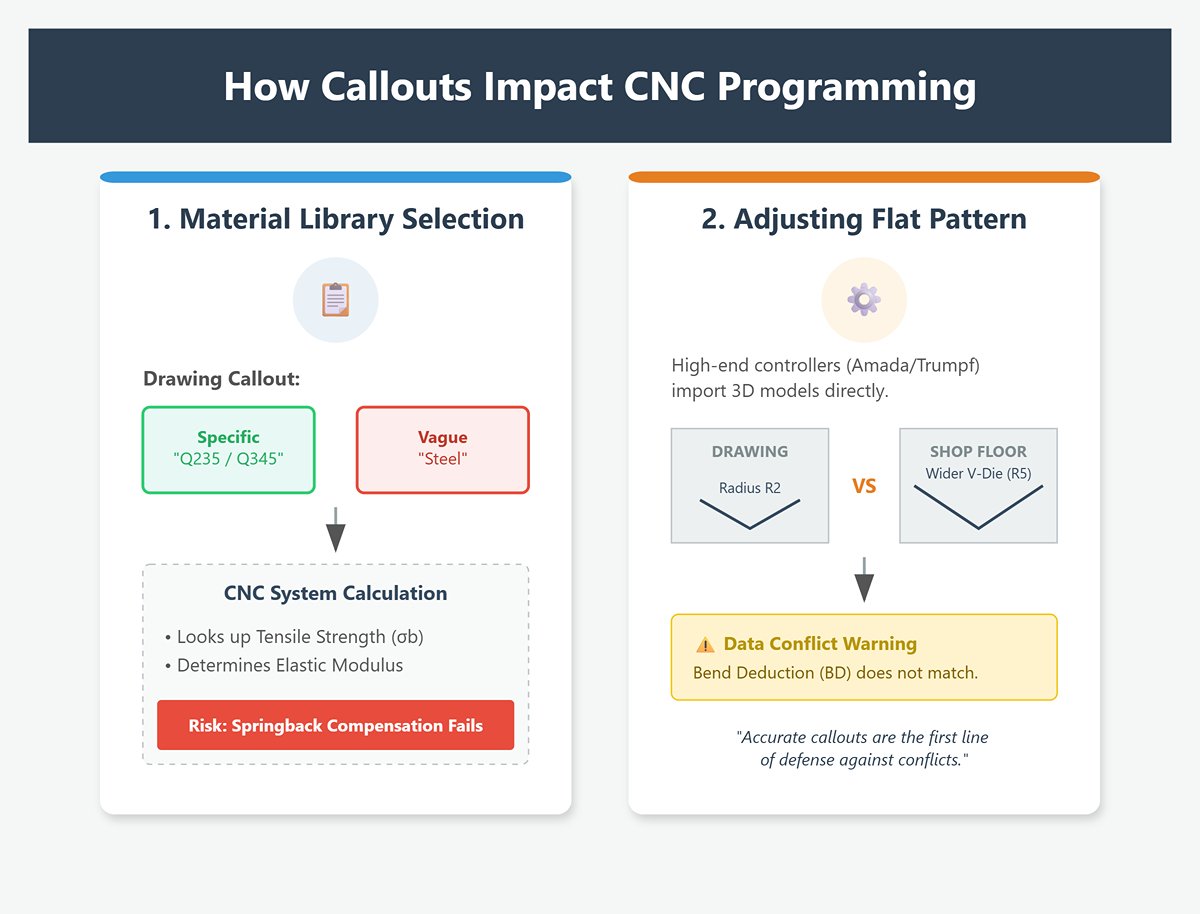
- Material library selection: The operator first calls up material properties in the CNC system that match the drawing’s callouts (for example, tensile strength $\sigma_b$). If the drawing only says “steel” without specifying whether it is Q235 or Q345, the operator may choose the wrong elastic modulus, causing the system’s pre‑calculated springback compensation to fail.
- Adjusting the flat pattern: High‑end machine controllers (such as Amada’s AMNC or Trumpf’s Delem systems) allow 3D model import. If the bend deduction (BD) on the drawing is calculated based on an R2 die, but the shop uses a wider V‑die that produces an R5 radius to reduce effort, the controller will immediately warn or flag that the flat pattern does not match. Accurate callouts are the first line of defense against this kind of “data conflict.”
4.2 Tool Selection and Process Setup
On the shop floor, the authority to select tooling usually lies with the operator or shift leader. That does not mean designers can ignore this step. Understanding how tools are chosen helps designers optimize angle callouts in reverse.
The “8× rule” and radius drift The golden rule for choosing the lower die V‑opening is:
(where T is material thickness).
- Core conflict: In air bending, the natural inside bend radius (Ir) is roughly 16% of the V‑opening (i.e., Ir ≈ V/6).
- Design takeaway: If your drawing calls out an inside radius of “R1.0” while the material thickness is 3 mm (which by standard practice uses a V24 die and produces about R4.0), that callout is impossible to achieve in practice. The operator will be forced to choose between switching to a non‑standard die or deviating from the specified radius. Best practice is to allow the inside radius to follow the natural result of the chosen die, unless a specific assembly or clearance requirement demands otherwise.
Tonnage limits and safety thresholds When calling out sharp angles (such as 30°) or bending thick plate, you must consider the die’s load capacity (tonnage limit). The operator will calculate the required tonnage based on the specified angle:
Suppose the angle is too small (e.g., 15°), forcing the operator to use a very narrow V‑opening. In that case, the required tonnage may instantly exceed the die’s allowable tonnage per meter, causing die failure. A well‑designed drawing should never push up against physical limits.
4.3 First‑Piece Setup and Trial Bending
No algorithm, however advanced, can perfectly predict batch‑to‑batch variation in material properties. First‑piece setup is the closed‑loop process used to “calibrate out” these errors, and it is also the litmus test for whether angle callouts are reasonable.
The first bend: measurement and “teaching” After running the program for the first time, the operator will almost never get a perfect 90° right away.
- Trial bend: Perform the first bend on scrap material.
- Measurement: Use a digital protractor or laser angle gauge to measure the actual angle (for example, 91.5°).
- Correction: This is the critical step. The operator does not manually calculate how many more millimeters the ram should travel. Instead, they directly enter the measured “91.5°” into the CNC controller’s angle correction field.
- Adaptive adjustment: The controller automatically back‑calculates the depth difference and applies the compensation on the next bend.
Introducing crowning compensation For long parts (such as a 3‑meter cabinet housing), it is common to see “larger angle in the middle, smaller at both ends.” This is caused by slight deflection of the ram and bed under load. During setup, if the drawing specifies strict straightness or full‑length angle tolerances, the operator must activate the hydraulic or mechanical crowning system. Callout tip: For extra‑long bends, it is advisable to mark inspection check points on the drawing to guide the operator in fine‑tuning the crowning curve locally.
Locking in from trial to mass production Once the first article’s angles have been verified as acceptable using a CMM or dedicated gauges (First Article Inspection Pass), the operator will lock in that parameter set. Only then do the drawing callouts truly transform from ink on paper into hard rules that govern thousands of repeat cycles.
This entire process makes one thing clear: an accurate angle callout is far more than just a number. It is the source code that drives the controller’s algorithms, guides tool selection, and defines compensation logic. Any ambiguity at the design stage will be amplified here into machine downtime or piles of scrap.
V. Quality Assurance Module: Measurement, Verification, and Closed‑Loop Optimization
Quality assurance (QA) is never a “postmortem” at the end of production; it is the primary data source that drives continuous improvement in bending processes. In precision sheet metal manufacturing, only when standards are clearly “measurable” do drawing callouts carry real contractual weight.
This module moves from basic physical gauges to intelligent adaptive technologies, building a complete closed loop from verification to optimization.
5.1 Angle Measurement Tools and Methods
To do a good job, you must first sharpen your tools. The measurement tools you choose directly define the upper limit of achievable accuracy. Based on application scenarios, we divide measurement methods into three levels:
1. Shop-Floor Level: Fast Go/No-Go Decisions
- Universal Bevel Protractor: A classic instrument in mechanical manufacturing. Although it can achieve a resolution of 5 arcminutes, readings depend heavily on operator experience, and short flanges are prone to error due to insufficient contact surface.
- Digital Angle Gauge: A standard tool in modern workshops. It magnetically attaches to the workpiece surface for rapid angle readout.
- Expert warning: A digital angle gauge measures angle relative to gravity. You must “zero” it on the press brake bed or on the side of the lower die first; otherwise, any unevenness in the foundation will be falsely interpreted as bending error.
- Custom Templates / Check Fixtures: For high-volume production, laser-cut metal templates are the most efficient solution. They don’t just check the angle; they can simultaneously verify inside radius and flange length.
2. Inspection-Room Level: Full-Size Verification (FAI)
- Coordinate Measuring Machine (CMM): The ultimate arbiter whenever there is a measurement dispute.
- Measurement strategy: A CMM does not directly “measure an angle.” Instead, it probes multiple points to fit two planes and then calculates the angle between them. This approach filters out local surface irregularities (such as oil-canning) that could otherwise cause misjudgment.
- Callout guidance: If the drawing requires extremely tight angular tolerance (e.g., ± 0.2°), it is recommended to add a note such as “Inspection per CMM standard” to indicate that the supplier must have the corresponding inspection capability.
3. Critical Measurement Rule: Three-Point Verification Never measure only at the center of the bend. Because of press brake deflection, the standard inspection routine must cover three positions: left end, center, and right end.
- If the center angle is >90° while both ends are =90°: the crowning (deflection compensation) is insufficient.
- If the center angle is <90° while both ends are =90°: the crowning is excessive.
Only when all three readings agree can you say that the process parameters are truly locked in.
5.2 Intelligent Measurement and Adaptive Technologies (Advanced)
This is the “superpower” that Industry 4.0 brings to sheet metal bending. In traditional workflows, we rely on a loop of “trial bend – measure – adjust.” On presses equipped with an Adaptive Bending System, however, measurement and correction occur during the bending stroke itself.
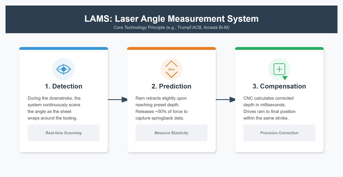
Core Technology Principle: LAMS (Laser Angle Measurement System)
Technologies such as Trumpf ACB or Amada Bi-M use laser or mechanical probes mounted on the ram or tooling to implement the following closed-loop logic:
- Detection: During the downstroke, the system continuously scans the angle as the sheet wraps around the tooling.
- Springback Prediction: Once the ram reaches the preset depth, it retracts slightly and releases about 50% of the force. The system instantly captures the material’s springback response.
- Dynamic Compensation: Based on the measured springback, the CNC controller calculates a corrected penetration depth within milliseconds and, within the same stroke, drives the ram down again to the final position.
Disruptive Impact on Callout Strategy
- Eliminating the “material batch” excuse: Regardless of batch-to-batch variation in yield strength, the adaptive system calculates compensation individually for each blank. A drawing tolerance of ±0.5° is no longer dependent on near-mystical operator experience; it becomes a deterministic outcome ensured by the algorithm.
- First Part Good: For expensive materials (such as titanium alloys) or low-quantity, high-mix jobs, this technology effectively removes the cost of trial parts. In engineering discussions, whether a supplier has this capability directly determines how tightly you can specify angular tolerances.
5.3 Typical Defects and Troubleshooting
When finished parts fail to meet drawing callouts, you need a structured troubleshooting approach. Below are four of the most common bending defects and their root causes:
| Defect phenomenon | Physical Root Cause | Solution and Annotation Optimization |
|---|---|---|
| Banana Effect (Canoe Effect) | Press brake deflection. Under high tonnage, the ram bows upward and the bed sags downward, so the center sees less load than the ends, resulting in a larger angle (under-bend) in the middle. | Production: Adjust CNC crowning (deflection compensation). Design: For very long parts (>2 m), consider relaxing straightness requirements in the central region. |
| Edge Cracking | Tensile limit exceeded. The inside bend radius (IR) is smaller than the material’s minimum recommended bend radius, or the bend line is parallel to the material grain direction. | Design: Increase the specified inside radius (IR). Process: Rotate the nesting orientation by 90° so the bend line is perpendicular to the grain. |
| Unstable Angle (Drifting) | Material anisotropy. Variations in thickness tolerance or hardness within the same batch cause inconsistent springback. | Process: Use a press brake equipped with an angle measurement system, or switch to coining (bottoming) if the tooling can safely withstand the load. |
| Die Marks | Excessive contact stress. The sheet is dragged hard over the edges of the V-die, causing visible indentations. | Production: Use urethane protective film or a roller/mark-free bottom die. Design: Add a prominent note such as “NO VISIBLE DIE MARKS” on the drawing, understanding that this typically increases manufacturing cost. |
Expert summary: A well-defined bend callout is far more than just an angle value; it orchestrates material properties, machine capability, and inspection methods as a coherent system. Once you understand the limitations of your measurement tools, the potential of adaptive technologies, and the root causes of common defects, your drawing stops being a set of cold lines and numbers—it becomes precise production code that directs the shop floor to deliver flawless parts. With this, we complete the full closed loop from understanding, calculation, and callout definition to on-the-floor validation.
VI. Conclusion
Mastering bend angle callouts is the cornerstone of profitable sheet metal manufacturing. It demands a systematic approach—from understanding springback physics and applying rigorous engineering standards to leveraging intelligent programming and in-process adaptive measurement.
Implementing these principles requires world-class technology. At ADH Machine Tool, we provide complete bending solutions that turn these complex concepts into your daily reality. Our press brakes, equipped with state-of-the-art adaptive angle control and intuitive software, are engineered for absolute precision from the very first piece.
Ready to eliminate guesswork and slash your scrap rate? Let our team demonstrate how our technology can revolutionize your production floor. Your journey to absolute bending precision starts here—visit ADH Machine Tool or contact us to take the next step.


