Knowing how to change a motor on a hydraulic press brake is a critical, high-stakes procedure for any maintenance professional. This is not merely a mechanical task; it's a comprehensive engineering exercise where a single oversight in diagnosis or installation can lead to catastrophic pump failure and significant downtime.
This definitive guide moves beyond basic instructions to provide a systematic, professional-level framework, ensuring you execute the replacement flawlessly and transform a reactive repair into a long-term reliability gain.
I. Decision & Diagnosis: Critical Facts to Confirm Before Touching a Single Bolt
Before you grab a wrench and loosen the first bolt, the most expensive mistake you can make is to assume. The power unit of a hydraulic press brake is a tightly coupled electro-hydraulic-mechanical system. Many symptoms that look like “motor failure” are in fact distress signals from the hydraulic system. This section walks you through a surgeon‑level diagnostic process to make sure you’re removing the real “diseased tissue,” not an innocent bystander.
1.1 Symptom Decoding: Identifying the Real Culprit, Not a Scapegoat
In a hydraulic system, the motor is often the silent scapegoat. When you hear strange noises or nuisance tripping, follow the steps below before you even think about pulling the motor.
- False-Fault Screening: Don’t Be Fooled by Sound and Load
- Cavitation Noise vs. Bearing Noise: These are very easy to confuse. If you hear a crunching sound like “gravel in a blender” or a high‑pitched screech, it’s usually a sign of cavitation in the hydraulic pump or air ingress on the suction line, not damaged motor bearings.
- Relief Valve or Mechanical Jamming: If motor current spikes and the thermal relay trips, don’t rush to label it a coil short. First inspect the relief valve to see if it is stuck closed, and check whether the ram guides or slides are mechanically seized. These external issues can load the motor to several times its rated torque and create a “false overload.”
- Single Phasing: This is the number‑one motor killer. Verify that the incoming three‑phase supply is balanced. If one phase is missing, the motor will emit a low humming sound and overheat rapidly. Swapping in a new motor without fixing the supply issue will only result in another burnt motor within minutes.
- Electrical Health Check: Let the Numbers Speak
- Insulation Resistance Test (Megger Test): This is the gold standard for judging winding health. Isolate the motor from the power source and measure insulation resistance to ground using a 500 V or 1000 V megohmmeter.
- > 100 MΩ: Insulation is in good condition.
- 1 MΩ – 10 MΩ: Insulation is degraded, likely moisture‑affected; drying or baking is recommended.
- < 1 MΩ: Insulation breakdown; the motor must be replaced.
- Contact Inspection: Check the contactor tips in the control panel. Severe oxidation or pitting increases contact resistance and causes voltage imbalance at the motor terminals. Long‑term operation under such conditions leads to irreversible thermal damage.
- Insulation Resistance Test (Megger Test): This is the gold standard for judging winding health. Isolate the motor from the power source and measure insulation resistance to ground using a 500 V or 1000 V megohmmeter.
- Mechanical Decoupling Test: The Ultimate Verification
If you still cannot pinpoint the noise source, perform a decoupling test.- Pass/Fail Criteria: After the motor has been mechanically separated from the pump or load, run it alone. If it runs smoothly, sounds normal, and the three‑phase current is balanced (typically 20%–30% of rated current), then the motor is healthy. In that case, the fault lies 100% in the hydraulic pump or downstream mechanical components.
1.2 Repair or Replace? An ROI‑Based Decision Model
Once you’ve confirmed that the motor itself has failed (for example, burnt windings, seized bearings, or a broken shaft), choosing between rewind/repair and replacement is not just a price comparison. It’s a calculation that must factor in downtime cost and energy‑efficiency payback.
- Economic Evaluation: Total Cost of Ownership (TCO)
- The Repair Trap: For standard low‑power motors (< 15 kW), the combined cost of rewinding, bearing replacement, labor, and logistics often reaches 60%–70% of a new motor. On top of that, a rewound motor typically suffers a 1–2 percentage‑point drop in efficiency.
- Efficiency Dividend: Consider using this failure as an opportunity to upgrade to an IE3 (Premium Efficiency) or IE4 (Super Premium Efficiency) motor. For a press brake running 8–16 hours per day, the energy savings from the new motor can usually recover the price difference within 12–24 months.
- Time Factor: Downtime Loss vs. Lead Time
- Risk Assessment
- Risks of Reviving an Old Motor: Even if you successfully rewind an old motor, the stator core losses, mechanical strength of the housing, and corrosion at sealing surfaces all remain hidden time bombs.
- Warranty Advantage: New motors typically come with 1–2 years of OEM warranty, whereas repair shops usually offer only 3–6 months of limited coverage. For reliable operation over the next 3–5 years, unless you’re dealing with a special‑purpose non‑standard motor or a very large unit, “replace rather than repair” is the best practice in industrial maintenance.
II. Strategic Preparation: Engineering for a First‑Time‑Right Replacement
In almost any industrial maintenance project, 80% of success or failure is decided before anyone picks up a tool. Replacing the motor on a hydraulic press brake is far more than a simple “swap‑out.” It’s a coordinated engineering task involving gravity management, electrical isolation, and precision mechanical alignment. The goal of this section is to turn every potential variable into a controlled, standardized step so the job is completed right the first time within the planned downtime window.
2.1 Zero‑Energy State and Lockout/Tagout (LOTO)
Hydraulic press brakes are especially hazardous because they store multiple types of energy, many of them hidden. Simply switching off the main disconnect is nowhere near enough. You must establish a true zero‑energy state before entering the work zone.
- Isolating All Power Sources: Beware of “Shadow Power”
- Main Power Isolation: Disconnect the three‑phase high‑voltage supply feeding the main drive motor (typically 380 V/480 V) and apply a physical lock to the isolator.
- Control Circuit Shutdown: On many press brakes, the PLC, HMI, and safety light curtains are powered by separate 24 V DC or 110 V AC control transformers. Even with the main motor off, the control panel may still be live. Always consult the electrical schematic and disconnect all auxiliary supplies.
- Independent Cooling Systems: If the machine has separate air or water cooling pumps, they are often fed from circuits independent of the main motor. These must also be locked and tagged out.
- Hydraulic Energy Release: Taming the Invisible Beast
This is the single most critical safety step for hydraulic equipment.- Mechanically Securing Gravity Loads: Before shutting down the hydraulic pump, make sure the ram is at bottom dead center (fully closed), or support it mechanically with certified safety blocks. Never rely on the oil trapped in the cylinders to hold the ram. Once you disconnect a line or an internal leak develops, the ram can drop instantly, causing catastrophic injury.
- Depressurizing the Accumulator: Press brakes often use high‑pressure accumulators to speed up the return stroke. After shutdown, the accumulator can still be holding pressures up to 200 bar. Open the accumulator bleed valve (ball valve) manually and watch the pressure gauge until it reaches zero. Never attempt to bleed pressure by cracking a fitting—high‑pressure oil mist can easily penetrate skin and cause severe tissue necrosis.
- Executing LOTO (Lockout/Tagout): Follow the “one person, one lock, one key” rule. Every person involved in the work (electricians, mechanics, etc.) must place their own lock on each energy isolation point. Only after the last lock has been removed does the machine have the physical precondition to be restarted.
2.2 Spare Part Matching and Supply Chain Confirmation

One of the most frustrating causes of maintenance delays is discovering that the new motor “doesn’t fit” only after you’ve removed the old one. During procurement, you need to decode the nameplate data with the precision of a forensic investigator.
- Decoding nameplate data: the DNA of physical dimensions
- Frame size is critical: This is the key parameter that determines interchangeability (for example, IEC 160L or NEMA 254T). It defines the foot mounting bolt pattern, shaft height, and shaft diameter. If the frame size doesn’t match, on-site drilling and modification will not only be time‑consuming, but will also compromise the rigidity of the base.
- Flange configuration pitfalls: Hydraulic motors are often directly flanged to the pump. Be sure to distinguish between B5 (large flange, through holes, bolts inserted from the pump side) and B35 (with feet and with flange). Verify the register (rabbet) diameter and the pitch circle diameter (PCD) of the bolt holes to ensure a perfect fit with the hydraulic pump bell housing.
- Voltage and efficiency class: Confirm whether the new motor is inverter‑duty, especially if the press brake uses a servo pump control system. A standard motor running at low frequency and high torque may overheat due to poor cooling and burn out.
- Coupling compatibility verification
- Bore tolerance: Never assume that motors of the same power rating have identical shaft diameters. The new motor shaft may differ slightly due to metric vs imperial standards. Prepare a vernier caliper in advance, or simply purchase an extra set of half‑couplings as backup.
- Spider/insert replacement: The elastomeric spider in the coupling is a consumable component. Regardless of the wear level of the old insert, it must be replaced without exception when changing the motor to ensure optimal damping and shock absorption.
- The “invisible consumables” checklist Don’t let a single missing screw hold up the entire job. Prepare in advance: new hydraulic pump gaskets or O‑rings, thread‑locking compound (such as Loctite 243), and crimp lugs sized for the new motor’s terminal studs.
2.3 Site conditions and special tool preparation
To do a good job, you must first sharpen your tools. Given the cramped internal spaces of hydraulic press brakes, standard tools are often inadequate.
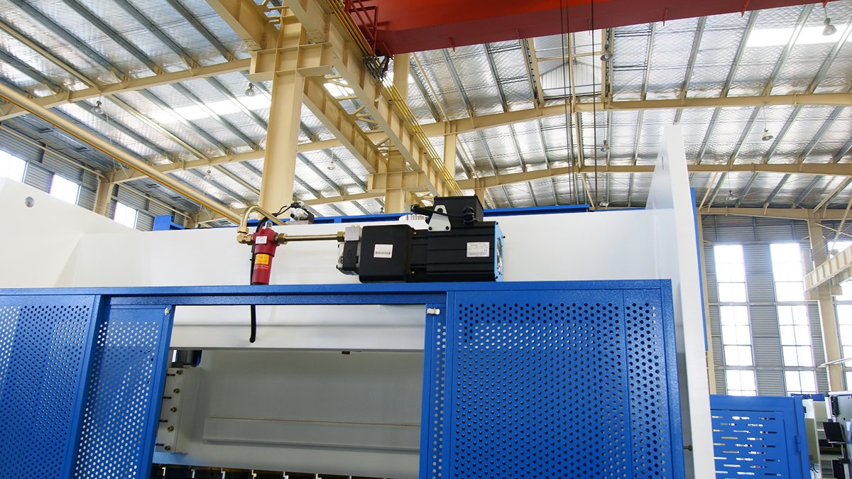
- Lifting plan Motors are usually mounted on top of the tank or deep within the machine, where access is tight.
- Anti‑tip lifting: Prepare soft lifting slings (to avoid scratching the shaft extension) and a chain hoist. For motors with an offset center of gravity, use a spreader beam to prevent the motor from rolling during lifting and striking precision hydraulic valves or damaging the tank cover.
- Pump shaft protection: Define a removal strategy that ensures the motor is drawn straight out of the bell housing in a horizontal line. Never use the pump shaft as a lever or fulcrum; doing so will destroy the shaft seal instantly.
- Precision measuring tools: abandoning “rule‑of‑thumb” work
- Laser alignment system or dial indicator: Coaxial alignment is a decisive factor for hydraulic pump life. Eyeballing alignment is completely unacceptable; you must have measuring tools with at least 0.01 mm accuracy.
- Feeler gauges: Used to detect soft foot conditions. This is a detail many seasoned technicians still overlook—if the four motor feet are not in the same plane, tightening the bolts by force will twist the motor frame, resulting in bearing offset loads and abnormal vibration.
- Torque wrench: Have torque wrenches covering the 20–200 N·m range to tighten flange bolts and anchor bolts to the specified torque, preventing loosening from vibration or thread yielding from over‑tightening.
III. Disassembly: a systematic reverse‑engineering process
Disassembly is not mindless destruction; it is a carefully organized reverse assembly exercise. Every part you remove and every cable you disconnect is both a clue to the root cause of failure and a reference for installing the new motor correctly. The goal at this stage is not only to remove the old motor, but also to clear every possible obstacle to a “zero‑error” installation of the new system.
3.1 Electrical isolation and information retention: physical backups of your data

Cutting cables is not just a physical action; it is also a data‑preservation step. On a hydraulic press brake, wiring mistakes can be extremely costly—a motor running in reverse can destroy the hydraulic pump within seconds due to dry friction or cavitation.
- Recording wiring “DNA”: rejecting color‑based guesswork Color codes for industrial cables vary across eras and manufacturers. Relying on “red to red, black to black” is a very dangerous gamble.
- Physical labeling method: Before disconnecting any wires, you must use number sleeves or waterproof tags marked U/V/W (IEC) or T1/T2/T3 (NEMA) to create a one‑to‑one correspondence between the supply cables and the motor leads.
- Photo documentation: Use a smartphone with flash to take high‑resolution photos inside the terminal box, making sure the terminal positions, jumper configuration (star/delta), and grounding point are clearly visible. This photo will be your final authority when restoring the wiring.
- Non‑destructive removal and IP protection The terminal box is the motor’s last line of defense against oil contamination and metal dust.
- Cable gland protection: When loosening the cable gland, prevent the cable from twisting with it, which could break the conductors inside. After removal, immediately check the gland’s rubber seal for aging or cracking. A failed seal can allow moisture ingress, leading to insulation breakdown and motor burnout within months.
- Terminal hardware handling: Use the correct socket wrench to remove crimp lugs; never twist them off with pliers. As soon as the nuts and washers are removed, re‑install them on the original studs to prevent small parts from falling into the motor fan cover or hydraulic lines and causing secondary damage.
3.2 Mechanical separation and protective disassembly: the art of applied mechanics
This is the highest‑risk phase of the disassembly. Improper stress release or rough handling can easily bend the pump shaft or deform the bell housing.
- “Blind work” inside the bell housing The motor and hydraulic pump are usually buried deep inside or alongside the tank and connected via a bell housing.
- Releasing hidden locks: Remove the inspection cover on the bell housing. Turn the motor by hand (rotating the cooling fan) and look through the window for the coupling set screw. These small hex socket set screws are usually secured with thread‑locker, so use a high‑quality long‑arm hex key to fully loosen or remove them; otherwise, the coupling will not come off the shaft.
- No brute force: the absolute authority of the puller
- Strict no‑hammering rule: This is the red line for professional technicians. Never strike the motor shaft or coupling directly with a hammer in an attempt to separate them. Axial impact loads are transmitted straight into the pump’s precision bearings and swash plate, causing irreversible brinelling. The pump will then howl in operation and fail prematurely.
- Proper separation tools: If the coupling hub is a tight fit on the shaft, you must use a three‑jaw puller or a dedicated removal tool. Apply the pulling force evenly to the base of the hub while the puller screw bears on the center drill point of the shaft, and draw it off smoothly.
- Stress-relief sequence When loosening the flange bolts between the motor and the bell housing, follow a crisscross (diagonal) pattern and back them off completely in two to three passes. This prevents uneven loading from causing slight warping of the aluminum bell housing, which would compromise shaft alignment (coaxiality) during reassembly.
3.3 Removing the old motor and inspecting critical components: on-site forensic analysis
Once the motor is removed, the exposed cavity becomes the best window into the hydraulic system’s overall health. Do not rush to install the new motor; first complete the two critical “health checks” below.
- Pump shaft health check (Runout Check) In many cases, motor bearing failures are actually caused by runout of the hydraulic pump shaft. If this root cause is not eliminated, the new motor will simply become the next victim.
- Dial indicator measurement: Mount a magnetic base on the bell housing or another rigid surface, and set the dial indicator tip perpendicular to the exposed pump input shaft. Slowly rotate the pump shaft 360° and observe the dial reading.
- Acceptance criteria: For most hydraulic press brake pump groups, pump shaft radial runout (TIR) must be strictly kept within 0.05 mm (0.002 in.). Any value above this indicates worn pump bearings or a bent shaft, and the pump must be repaired or replaced before installing the new motor.
- Restoring the flange surfaces Inspect the mounting flange faces on both the pump side and the bell housing side.
- Cleaning and deburring: Remove any remaining sealant, rust, or paint buildup. Use a fine oil stone to gently skim the surface and eliminate any scratches or burrs created during disassembly.
- Flatness verification: Even tiny high spots will translate into twisting stress in the motor frame once the bolts are tightened, causing a “soft foot” condition and drastically shortening bearing life. Make sure all mating surfaces are clean, metallically bright, and perfectly flat.
IV. Precision Installation: The Critical Step That Determines Equipment Life
Many service technicians mistakenly assume that installation is simply the reverse of disassembly. This is a dangerously misleading mindset. Disassembly can be rough; installation must be performed like delicate surgery.
A proper installation not only determines whether the motor will turn, it directly influences whether the hydraulic pump group will run reliably for five years or fail within five months. This chapter walks you through a precision assembly standard based on a “zero stress” principle.
4.1 Pre‑Assembly and Fine Detailing
The devil is in the fit tolerances. Before lifting the motor into place, you must complete all critical pre‑work on the bench. Done properly, this can save you hours of rework on site.
- Key finishing: Aim for a “snug slip fit”
- No hammering—ever: This is the dividing line between a novice and a professional. Never drive a parallel key into the motor keyway with a hammer. The impact force is transmitted instantly to the precision bearings, creating invisible indentations (brinelling) on the raceways that later manifest as bearing noise and early failure.
- Hand‑fitting standard: New key stock is usually supplied with a slight oversize interference. You must chamfer the edges with a fine file and then use an oil stone to micro‑fit the key sides to within microns. The target is a “snug slip fit”—the key can be pushed in smoothly with your fingers, with no looseness and no sticking.
- Anti‑seize protection: Apply a thin, even layer of anti‑seize compound to the shaft extension and keyway to prevent fretting corrosion and make future disassembly easier.
- Coupling depth setting: Leave “breathing room” for thermal growth
- DBSE calculation: Do not simply push the coupling hub all the way to the shoulder. Always refer to the coupling drawing and calculate the standard distance between the two coupling faces (DBSE—Distance Between Shaft Ends).
- Thermal expansion allowance: As the motor heats up in operation, the shaft length increases slightly in the axial direction. For direct‑coupled hydraulic pumps, you must add an axial clearance of 1.5–2.0 mm on top of the nominal gap (the exact value depends on the frame size). If the coupling is set too tight, thermal growth of the motor shaft will push directly against the pump shaft, causing swash plate wear inside the pump or burnout of the rear motor bearing.
4.2 Lifting into Position and Eliminating Soft Foot

The real challenge begins once the motor is on the base. “Soft foot” is the number‑one hidden cause of high‑frequency vibration and uneven bearing wear in motors.
- Controlled seating on the base
- Use a spreader bar or two lifting points to keep the motor perfectly level as it is lowered. Do not release the lifting hook before the bell housing spigot is fully seated and engaged. Otherwise, the motor’s weight can deform the spigot fit.
- Soft foot detection and correction
- What soft foot looks like: Imagine a four‑legged table with one leg hanging in the air. If you forcefully tighten the hold‑down bolts, the cast‑iron motor frame will twist elastically. This destroys the concentricity between stator and rotor and deforms the bearing bores into an oval shape.
- Inspection procedure:
- Hand‑tighten all foundation bolts.
- One bolt at a time, loosen it and probe the gap between the foot and the base with a 0.05 mm feeler gauge.
- If the feeler gauge can enter, that foot is considered soft.
- Shim rules: Always use pre‑cut stainless steel precision shims to fill the gaps. Do not use tin can strips, saw blades, or other improvised materials—these will creep and compress over time, destroying alignment. Limit each foot to no more than three shims to avoid the “sponge effect.”
4.3 Core Procedure: Shaft Alignment (Coaxiality)
This is the equivalent of open‑heart surgery for the hydraulic press brake power unit. Even though a bell housing with a spigot fit is generally self‑centering, you must always verify alignment after changing motor brands or performing a major overhaul.
- Beyond what the naked eye can see
- Never trust “it looks straight.” For a 2‑pole motor running at 3000 RPM, parallel offset must be held within 0.05 mm, and angular misalignment within 0.05 mm per 100 mm of coupling diameter or span.
- Tool selection: A laser alignment system is the preferred choice; it can automatically calculate thermal growth compensation. If this is not available, use the double‑dial indicator method and verify results carefully. Relying on a straightedge across the coupling faces is strictly unacceptable.
- Tightening with controlled torque: Locking in your accuracy
- An incorrect tightening sequence can instantly destroy a painstaking alignment. Always use a cross‑star pattern when tightening fasteners.
- Three‑stage torqueing method:
- Stage 1: Set the torque wrench to 30% of the specified torque to establish initial seating.
- Stage 2: Increase to 70% and recheck alignment readings to confirm nothing has shifted.
- Stage 3: Go to 100% of the rated torque to fully lock the joints.
- This gradual tightening sequence allows internal stresses in the housing to relax and minimizes installation‑induced distortion.
4.4 Electrical Reconnection and Protection Restoration
Electrical reconnection is not just about making the circuit live; it is also about minimizing heating and electromagnetic interference.
- Terminal crimping: Target micro‑ohm‑level contact resistance
- Hydraulic crimping: For cables of 16 mm² and above, always use a hydraulic crimping tool with matching hexagonal dies. After crimping, the lug should show a clearly defined hex profile, and the cable insulation should butt tightly against the lug barrel with no exposed strands.
- Contact surface preparation: Before tightening terminal nuts, verify that the washers are made of pure copper. For high‑current joints, apply a thin layer of conductive grease to resist oxidation and maintain low resistance.
- Grounding continuity and VFD‑related protection
- High‑frequency interference control: Modern hydraulic press brakes are typically driven by VFDs (variable‑frequency drives). If grounding is inadequate, high‑frequency common‑mode currents will seek a return path through the motor bearings, causing electrical discharge machining (EDM) damage and creating washboard‑like grooves (fluting) on the raceways.
- Verification steps: Using a multimeter on the low‑resistance range, measure between the motor frame PE point and the main grounding bar in the control cabinet. The reading must be < 0.1 Ω. For high‑end systems, confirm whether the non‑drive end (NDE) of the motor is fitted with insulated bearings or whether a shaft grounding ring/brush is installed.
- Seal and enclosure restoration: Finally, check that the terminal box gasket is intact and tighten the cable glands to restore the enclosure rating to IP54/IP55, keeping oil mist and metal dust completely out.
V. Commissioning and restart: from “it spins” to “it runs reliably”
Finishing the mechanical installation is only the beginning of the system’s rebirth. For a high-precision electro-hydraulic press brake, powering up and test-running it casually is nothing short of a high-stakes gamble.
This section provides a standardized commissioning and acceptance procedure to catch potential catastrophic failures before production restarts, ensuring the machine not only moves, but does so reliably over the long term.
5.1 Critical checkpoint: rotation direction verification (The Bump Test)
Before closing the main contactor, treat motor rotation direction with absolute respect. This is the highest-risk single operation in the entire repair. A wrong rotation will destroy the hydraulic pump you spent hours installing in just a few seconds.
- Risk alert: reverse rotation = destruction Hydraulic pumps—especially gear and piston pumps—depend on precisely matched oil films for lubrication. If the motor runs backward, suction and discharge ports are effectively swapped, causing instant dry friction and high vacuum inside the pump. This leads to irreversible cavitation and surface scoring/sintering of internal metal parts. Remember: a hydraulic pump’s tolerance to reverse rotation is usually measured in seconds.
- Zero-risk test strategies
- Mechanical decoupling (recommended): The safest test is to run the motor without the pump. Before installing the coupling element—or by temporarily disconnecting the pump side—bump the motor while it is completely unloaded.
- Phase rotation meter pre-check (advanced): If you have a phase rotation meter, this is your moment to demonstrate professional practice. Check the incoming supply phase sequence before wiring, then manually rotate the motor shaft and measure its generated phase sequence. Confirm they match. This lets you be 100% sure of the rotation direction without energizing the motor.
- Ultra-short bump test (Bump Test): If you must test with the pump connected, two people are required. One stands by at the emergency stop; the other gives the motor a momentary bump and stops it immediately (energized for < 0.5 s). Acceptance criterion: observe the fan’s inertia rotation at the motor’s non-drive end; its direction must exactly match the arrow on the pump or bell housing.
- Correction: If reverse rotation is observed, apply LOTO, then swap any two of the three phase leads (U/V/W) either at the bottom of the contactor or inside the motor terminal box.

5.2 No-load and load test procedures
Once rotation direction has been verified, do not jump straight to full-load bending. Follow a three-stage test logic, gradually releasing the machine’s full capability.
- Stage I: no-load electro-mechanical run-in (No-Load Run) With the hydraulic system fully unloaded (relief valve set to minimum pressure), start the motor and let it run continuously for 10–15 minutes.
- Acoustic inspection: Differentiate between “electromagnetic noise” and “mechanical noise.” A healthy motor produces a smooth, low-pitched electromagnetic hum. If you hear a sharp whine (dry bearings), periodic “clicks” (coupling impact), or a low-frequency rumble (soft foot not eliminated), stop immediately and investigate.
- Current balance: Measure the three-phase current with a clamp meter. No-load current is typically 25%–40% of rated current. The key indicator is three-phase unbalance, calculated as (max − min) / average, which must not exceed 5%. Excessive unbalance suggests winding issues or abnormal supply voltage.
- Stage II: hydraulic pressurization and venting (System Pressurization) Gradually increase the relief valve setting so the system develops initial circulation pressure, but do not perform bending operations yet.
- Forced air purging: Air may have entered the lines during motor replacement. At low pressure, repeatedly cycle the ram through full stroke travel up and down to carry air back to the tank with the return oil. Watch the oil level in the reservoir—if you see a lot of white foam, there may be cavitation or air leaks on the suction side.
- Micro-leak inspection: Using a flashlight, carefully check all flange joints and hose fittings. The new motor’s vibration characteristics may differ from the old one, potentially triggering leaks at marginal seals that previously “just held.”
- Stage III: full-load verification (Full Load Cycle) Load a test die and perform actual sheet bending so the system reaches maximum working pressure.
- Peak current capture: Monitor motor current as the ram reaches bottom dead center and pressure is held. This value must never exceed the nameplate full-load amperage (FLA). If it does, the motor may be overloaded due to excessive internal leakage in the pump or excessive voltage drop on the supply.
- Thermal imaging scan: After at least 30 minutes of continuous operation, scan the motor with an infrared thermal camera. Focus on the terminal box (for loose, overheating connections), both bearing housings, and the stator frame. For F-class insulated motors, permissible temperature rise is typically 80K–105K, but if bearing temperature spikes more than 20°C in a short time, it usually indicates misalignment or excessive grease.
5.3 Final acceptance and handover
The real endpoint of the repair is not simply that the motor runs, but that the data loop is closed and the work area is fully restored.
- Establish a digital baseline (Baseline Data) Do not let this repair remain a one-off “black box” event. On the acceptance report, record the following key data in detail as the baseline for future condition-based maintenance (CBM):
- No-load current (three-phase average)
- Full-load peak current
- Bearing temperature after 1 hour of operation
- Vibration level at the flange (if measurement is available)
- Value point: Six months from now, if the equipment acts up again, this data will be the only objective basis for judging whether the motor has started to age.
- Restoring 6S on site: True professionalism often shows in the moment you leave the work area.
- Cleaning: Wipe fingerprints and grease off the motor housing, and remove any discarded tape and old bolts from the floor.
- Putting everything back: Confirm all guards and cover-plate screws are fully tightened, with no leftover parts lying around.
- Removing lockout: The maintenance lead should be the last person to remove the LOTO safety lock, then sign off in the maintenance log to close the loop, formally handing over a “healthy, safe, and clean” press brake to production.
VI. Extended value: Preventive maintenance and failure avoidance
6.1 Diagnosing common post‑installation issues (FAQ)
The first 48 hours after the equipment is brought back online is the high‑risk window for “infant mortality.” When abnormal signals appear, fast and accurate diagnosis is the key to preventing a second shutdown.
- High‑frequency whine: the “silent killer” you can barely hear If you notice a sharp, piercing high‑frequency noise that clearly isn’t mechanical rubbing, it’s usually not the bearings “crying” but the electromagnetic field “resonating.”
- VFD carrier frequency out of tune: When a VFD drives the motor, if the high‑speed switching frequency (carrier) of its internal IGBTs happens to overlap with the natural frequency of the stator, a high‑pitched whine can occur. Fix: Go into the VFD parameter settings and slightly adjust the carrier frequency (typically in the 2 kHz–16 kHz range) to move away from the resonance point; the noise usually disappears instantly.
- Coupling “singing”: If the sound varies with load, it’s very likely that the coupling’s axial gap (DBSE) was left too small. Once the system heats up, thermal expansion causes the elastomer to be clamped solid, so it can no longer provide cushioning, leading to high‑frequency micro‑impacts between metal parts.
- Trip at startup: when current “lies” to you If the motor trips protection as soon as it starts, the motor itself is often fine—the control logic is what’s “lying.”
- Star–delta wiring trap: For high‑power press brakes, if the terminals in the junction box are mistakenly wired in delta when they were intended for star‑start, the inrush current at startup can spike to more than seven times the rated value, blowing straight through the overload relay’s protection.
- Overload relay not updated: This is the most common rookie mistake. The new motor’s full‑load current (FLA) may differ slightly from the old one (especially after upgrading to an IE3 high‑efficiency motor). You must reset the overload relay trip current according to the new nameplate, otherwise the protection will either nuisance‑trip or fail to trip when needed.
- Hydraulic oil overheating: the “barometer” of efficiency Put in a new motor but the oil temperature is even higher? That usually points to a hidden issue in the hydraulic pump.
- The harsh law of energy conversion: If the hydraulic pump is badly worn, internal leakage will increase sharply. The stronger torque of the new motor forces the oil through worn clearances at higher pressure; this behaves like a large throttling valve, converting mechanical energy directly into heat. In this situation, rising oil temperature is the final ultimatum that the hydraulic pump needs to be replaced.
6.2 Whole‑lifecycle management strategies
Turning lessons from a one‑off repair into enforceable long‑term practices is what separates a mere “parts changer” from a true “equipment manager.”
- Lubrication discipline: no “chemical warfare” allowed Mixing motor bearing greases is one of the most underrated sources of disasters in industry.
- Polyurea vs. lithium: Many high‑end and imported motors (e.g., Siemens, ABB) are factory‑filled with high‑temperature polyurea‑based grease, while most plants stock lithium‑based grease. Chemically, these two thickener systems are completely incompatible.
- Consequences of mixing: Once mixed, they can react and cause the grease to harden like asphalt or liquefy and run out. Action directive: Install a permanent label next to the new motor’s grease fitting showing the OEM grease type, and assign a dedicated grease gun to it to physically eliminate cross‑contamination risk.
- Planned inspections: from “firefighting” to “preventive care” Build a defense system centered on condition‑based monitoring (CBM).
- Create a vibration fingerprint: When the new motor is running smoothly, record the vibration velocity values (mm/s RMS) at the bearing locations. Use this as the baseline and set alarm thresholds (e.g., 1.5× the baseline). As vibration slowly climbs over time, you’ll be able to predict bearing end‑of‑life up to three months before failure.
- Re‑torque critical bolts: Press brakes subject the structure to heavy impact loads. After replacing the motor, recheck and verify the torque on the foundation bolts after one week and again after one month to eliminate “initial relaxation.”
- Optimizing spare‑parts strategy: data‑driven inventory Don’t let the same problem trip you up twice.
- Redefine wear parts: Based on the pain points from this repair, reassess your spare‑parts list. The coupling elastomer (spider) and hydraulic pump seal kit should be classified as “red‑line inventory” items, with stock guaranteed at all times.
- Supply‑chain backup: Record the motor supplier, flange machining shop, and special‑tool providers validated in this job, and build a “one‑hour response network” so you’re fully prepared for the next challenge.
VII. Conclusion
Professional motor replacement on a hydraulic press brake enhances long-term performance and reliability through precise diagnosis and execution. For complex challenges, ADH Machine Tool offers genuine OEM parts, advanced troubleshooting, and expert on-site service. To schedule a service visit or discuss specific technical issues, you can directly contact us for one-on-one assistance. Contact ADH today for tailored support or visit our website to optimize your equipment’s efficiency.


