I. Rebuilding Core Understanding: Redefining the “Gold Standard” of Modern Sheet Metal Bending
In traditional sheet metal shops, bending is often treated as a rough process that depends on “feel” and brute force. But with the rise of precision manufacturing, air bending has long since moved beyond being just one more bending method. It has evolved into a precision manufacturing philosophy, where physical deformation is driven and governed by mathematical logic, , and where a high‑performance press brake becomes the core carrier of this philosophy on the shop floor. Mastering air bending is a mandatory step for any sheet metal professional who wants to move into the realm of advanced manufacturing.
1.1 Getting to the Essence of Air Bending: Understanding Beyond the Textbook Definition
Most people only understand air bending at a superficial level: the sheet does not touch the bottom of the die. That description is technically correct, but it hides what really matters—the core of the technology.
Core concept: Geometry-based control built on “three-point bending”
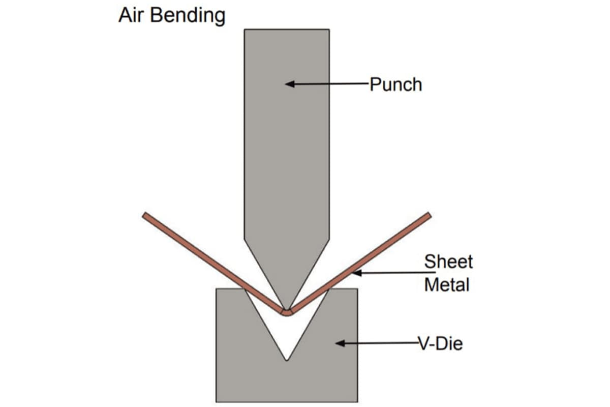
Air bending is a classic three-point bending physical model. The sheet metal contacts the tooling at only three defined points: the punch tip and the two shoulders of the V-opening in the die. Under the action of these three support points, the sheet is suspended and plastically deformed in mid-air.
Key distinction: depth defines angle (Depth is Angle)
This is the fundamental difference between air bending and other methods such as bottoming or coining. In bottoming, the final angle is determined by the geometry of the tools themselves. In air bending, the die angle does not equal the part angle. The final angle depends solely on how deep the punch penetrates into the die opening (the Y‑axis position).
- Control over depth: The operator or CNC system controls the slide stroke with micrometer-level precision, effectively “commanding” the metal to stop and remain at a target angle.
- What this mechanism implies: With a single 85° tool set, you can—by controlling depth—produce 90°, 120°, or even 160° angles. In other words, you are no longer physically constrained by the tool geometry when it comes to the finished part angle.
A visual way to think about it: the mechanics of interaction
Imagine what happens as the punch descends: the sheet is not simply “bent”; it is the scene of an internal battle of stresses.
- Inner radius: Under compressive stress, the metal lattice is squeezed and compacted.
- Outer surface: Under tensile stress, the metal lattice is stretched.
- Neutral axis: Inside the sheet there is a theoretical layer whose length remains unchanged throughout bending. In air bending, because there is no support from the die bottom, the shift and deformation of this neutral axis follow the laws of free bending. Grasping this behavior is the foundation for accurate K‑factor calculation and flat pattern compensation later on.
1.2 Process Routes Compared: Air Bending vs. Bottoming vs. Coining
When choosing a bending method, many engineers operate on guesswork. In reality, it is a trade-off among accuracy, required tonnage, and versatility.
- Air bending
- Forming principle: Three-point contact; the sheet does not rest on the die bottom.
- Advantages: Extremely high flexibility, lowest tonnage requirement (taken as the benchmark), and very low tool wear.
- Limitations: Final angle is strongly affected by material springback, so it demands very high control accuracy from the CNC system (a pain point that modern machines have largely solved).
- Bottoming
- Forming principle: The sheet is pressed down until it contacts the side walls of the V-opening, but not fully coined into the bottom.
- Characteristics: Typically requires the die angle to be matched to the target angle (for example, using an 88° die to form a 90° bend to compensate for springback).
- Tonnage requirement: Roughly 3–5 times that of air bending.
- Best suited for: Situations where you need reasonable accuracy but are limited to older presses with weaker control capabilities.
- Coining
- Forming principle: Extremely high pressure forces the sheet to flow into the very bottom of the die cavity, eliminating elastic recovery and thinning the material noticeably.
- Characteristics: Virtually zero springback and ultra‑high angle accuracy (within about 0.1°).
- Tonnage requirement: An enormous 8–10 times or more compared with air bending.
- Critical drawback: Severely shortens the life of both the press and the tools, and is generally only practical for thin sheet.
For more in‑depth comparisons of these methods in actual production scenarios, you can refer to the specialized Coining in Sheet Metal Bending Ultimate Guide.
Decision matrix
- When do you have to give up air bending?
When you must produce an extremely small inside radius (R < 0.6 × material thickness), or you need extremely tight batch‑to‑batch consistency on an older machine with no modern angle compensation system, coining or bottoming may be the necessary compromise. - Economic outlook: Air bending tools are highly universal—one tool set can cover a wide range of jobs, dramatically reducing tooling capital expenditure (Capex). At the same time, the lower tonnage requirement cuts machine power consumption and hydraulic wear (Opex), giving air bending the best overall ROI.
1.3 Why Do Modern Factories Use Air Bending for 80% of Their Bends?
Walk into a top-tier sheet metal plant—say, a Trumpf or Amada showcase facility—and you will see that most stations are running air bending. This is not a coincidence; it is the natural outcome of industrial evolution.
1. The engine of flexible manufacturing
In an era where “high mix, low volume” is the norm, setup time has become the number one killer of productivity. Air bending allows you to use a single standard tool set (for example, V = 12 mm, 85°) to produce any angle from 30° to 179° without changing tools. For job shops that frequently switch product types, this is not just an efficiency gain—it is a step‑change in their ability to stay competitive.
2. The physics behind the tonnage advantage
Air bending makes use of leverage, saving 60–80% of the force compared with bottoming. This leads to two immediate consequences:
- You can buy lower-tonnage, more affordable machines and still handle the same jobs.
- For thick plate, air bending is often the only practical option—very few presses can deliver the thousands of tons required to bottom or coin heavy-gauge material.
3. A natural partner for automation and CNC
Air bending is a process that is digital by design. Because the bend angle is determined by a numeric value (Y-axis depth), it maps perfectly onto CNC control. Engineers can define bend depths in offline programming software at their desks and send these settings to the press brake via DNC. This “data‑driven” nature makes air bending the only realistic choice for robotic bending cells and fully automated sheet metal lines.
In summary: Air bending is not a compromise; it is an intelligent upgrade that replaces brute force with precision control. It shifts our attention from “tool shape” to “process control,” which is exactly the mindset at the heart of modern manufacturing.
II. Physical Mechanisms and Mathematical Logic: The Underlying Code Behind Precision Control
In traditional sheet metal shops, veteran operators often rely on “feel” to set up the machine. But in modern manufacturing, where we chase micron-level accuracy, mathematics is the only truly reliable language. Air bending has become the dominant process precisely because it abstracts a complex metal forming behavior into a calculable physical model. Understanding this underlying logic is the watershed between being a mere “machine operator” and becoming a true “process engineer.”
2.1 Penetration depth rules everything: the geometry behind angle formation
The most fascinating—and also most confusing—aspect of air bending is this: the tool angle is not the same as the finished part angle. In bottoming, the die angle is a hard mechanical limit; in air bending, the die serves only as a support.
- Y-axis control law: depth defines angle
The core job of a press brake can be reduced to a single task: precisely controlling how deep the punch penetrates into the die (the Y-axis position). This is governed by a strict trigonometric relationship. Picture the punch tip and the two shoulders of the V-die forming an upside-down triangle. As the Y-axis moves downward, the height of this triangle changes and the bottom angle (your bend angle) changes with it.- Key implication: This means you need extremely accurate Y-axis control (modern machines typically achieve ±0.01 mm). Tiny depth errors are magnified by the geometry and turn into large angle deviations.
- Practical takeaway: With the same 85° lower die, you can produce 90°, 100°, 120° or even 160° bends simply by adjusting the penetration depth.
- Natural radius rule (The 16% Rule): the overlooked accuracy killer
Many engineers use a fixed inside radius (Ir) in their flat pattern calculations—fatal in mass production. In air bending, the inside radius is not defined by the punch tip radius; it forms “naturally” based on the V-opening width.- Physical reality: When the sheet is pressed and bent inside the V-opening, it follows the path of least resistance and forms a natural arc whose radius is roughly proportional to the span across the V.
- Rule of thumb: For mild steel with tensile strength around 420 MPa, the natural inside radius is about 16% of the V-opening (i.e. Ir ≈ V/6).
- Example: With a V12 die, the natural inside radius is about 2 mm; switch to a V24 die and the natural inside radius becomes about 4 mm.
- Knock-on effects: Any change in inside radius directly affects the K-factor and bend deduction. If your CAD model assumes R1 but you run the part on a V12 die that actually produces R2, your flat length will be wrong and the finished dimensions will be out of tolerance.
- Minimum flange height: the geometric safety boundary
The sheet must always bridge across the two shoulders of the lower die. If the flange is too short, the material will slip down into the V-opening during bending, ruining the part and potentially ejecting it dangerously.- Safety formula: Minimum flange height $b_{min} \approx 0.7 \times V$.
- This means that if you need to bend a 5 mm flange, the largest die you can safely use is V8 (0.7x8=5.6mm). That, in turn, limits the maximum sheet thickness you can bend in that setup.
2.2 Tackling the biggest headache: a systematic approach to springback
The moment the ram rises and the pressure is released, the stretched and compressed crystal lattice inside the metal tries to return to its original state. The bend angle opens up—this is springback. If you cannot predict it, you cannot control it.
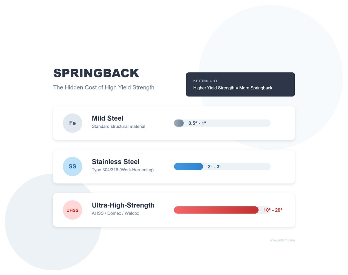
- Springback physics: the price of yield strength
Springback is roughly proportional to the material’s yield strength and inversely proportional to its Young’s modulus.- Mild steel: Relatively small springback (about 0.5°–1°).
- Stainless steel (304/316): Strong work hardening and significant springback (about 2°–3°).
- Ultra-high-strength steels (AHSS/Domex/Weldox): Behave like powerful springs, with springback up to 10°–20°. To end up with 90°, you may need to bend to 75° or even sharper.
- Over-bending strategy
Since springback is inevitable, the only viable countermeasure is to “fight fire with fire”—intentionally over-bend.- Calculation logic: Target angle = Programmed angle + Springback compensation.
- Common pitfall: Many operators bend to the nominal angle first, then re-press the part when they discover it has opened up. This is highly inefficient in automated production.
- Best practice: Build a material–tooling–springback database. For example, record that “3 mm 304 stainless on a V16 die requires bending to 88.5° to obtain a finished 90°.” High-end modern press brakes come with built-in material libraries and even Laser Angle Measurement Systems (LAMS) that measure the angle in real time during bending and automatically compensate for springback.
2.3 Force calculations and machine safety: non-negotiable limits
A press brake may look robust, but it is actually a precision instrument that can be surprisingly fragile. Incorrect parameter settings don’t just damage tooling—they can cause permanent accuracy loss in a machine worth hundreds of thousands of dollars.
- Breaking down the tonnage formula: square-law destructive power
The tonnage estimation formula for air bending is the foundation for all process parameters:
- t2 (thickness squared): This is the most dangerous term. If the sheet thickness doubles (say from 2 mm to 4 mm), the required tonnage doesn’t double—it quadruples.
- V (V-opening width): Because it is in the denominator, a smaller V-opening means higher pressure. Chasing a tiny inside radius by blindly choosing a very narrow V-opening can cause the required tonnage to soar and shatter the tooling in an instant.
- σb (tensile strength): Switching from mild steel (e.g., Q235) to stainless typically increases strength by about 50%, and the tonnage requirement rises in step.
- Frame deflection and center loading
- The “banana effect”: At near full tonnage, the upper beam and lower bed of the press brake deflect slightly under the enormous reaction forces, bowing upward in the center (larger opening in the middle, smaller at the ends). This is why long parts often show “correct angles at both ends, more open in the middle.” A crowning system is essential to counteract this inherent deflection.
- Risks of off-center loading: For convenience or out of habit, some operators bend only on one side of the press brake (off-center loading). Over time, this creates uneven forces on the ram and guides. Eventually, the frame undergoes permanent plastic deformation and the ram is no longer parallel. This damage is irreversible, much like scoliosis in the human spine—no matter how skilled the doctor, it can rarely be fully corrected. Always using center loading is the number one iron rule for protecting machine life.
Ⅲ. Process parameters and tooling strategy: from rule-of-thumb to scientific control
If the physics behind air bending is the “internal discipline,” then tooling selection and parameter settings are the “techniques and routines” that decide who wins. In modern precision manufacturing, relying on veteran operators to “judge by sound and feel” is no longer enough to meet micron-level tolerance requirements. We must build a scientifically quantified system grounded in material mechanics and geometric logic, turning trial-and-error uncertainty into well-defined, repeatable process plans.
3.1 The “golden rules” for V-opening selection—and when to break them
The lower die V-opening is the key variable in air bending that affects everything else. It directly determines the inside bend radius (IR), required tonnage, and minimum flange length.
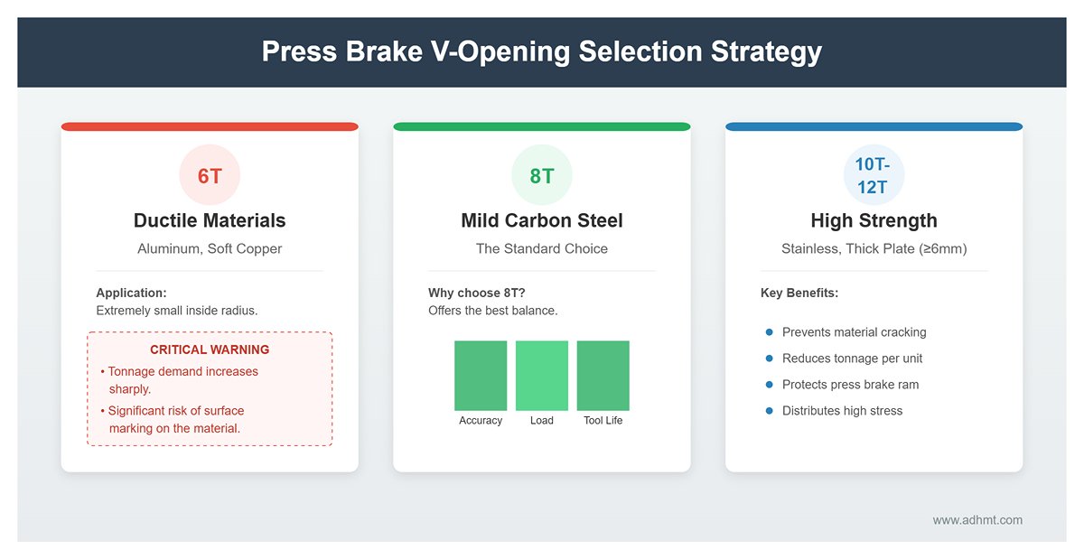
- Standard quick-reference: the limits of the 6T, 8T, 10T, and 12T rules The commonly cited “8 times material thickness rule” (V = 8T) is not a universal law; it is a reference point tailored to ordinary carbon steel with a tensile strength of around 420 MPa. A sound selection strategy should adjust dynamically based on material properties:
- 6T rule (V = 6T): For highly ductile materials such as aluminum alloys or soft copper, or when the drawing specifies an extremely small inside radius. Be aware that tonnage demand will increase sharply, and the risk of surface marking rises significantly.
- 8T rule (V = 8T): The standard choice for mild carbon steel, offering the best balance among bend accuracy, tonnage load, and tool life.
- 10T–12T rule (V = 10T–12T): Designed for stainless steel, high-strength steels, and thicker plate (typically t ≥ 6 mm). A larger V-opening helps distribute very high bending stresses to prevent cracking of the material, while also reducing required tonnage per unit length and protecting the press brake ram.
- Breaking the mold: when should you ignore the rules? Advanced process engineers know when to deliberately go against the standard guidelines. For example, to eliminate marks on visible surfaces, you might choose an extra-wide V-opening of 15T or even 20T, using the larger contact area to reduce pressure and avoid impressions—at the cost of a much larger natural inside radius. Conversely, to achieve an extremely short flange, you may be forced to use a narrow 5T die. In this case, you must carefully verify that tonnage remains within limits to avoid cracking the die.
- Tool compatibility: why use an 85° or even 80° lower die to bend a 90° part? This is a classic misconception in air bending. Many beginners assume that bending to 90° requires a 90° lower die. In reality, the lower die angle must be smaller than the target angle because all metals exhibit springback. To end up with a 90° finished angle, you may need to press the material down to 88° (overbending). If you use a 90° lower die, the sheet will touch both sidewalls once it reaches 90° (bottoming out), leaving no room to continue pressing to 88°. Choosing an 85° or 80° die is not about forming a sharp angle; it is about creating clearance for overbending, which is a geometric necessity to compensate for springback.
3.2 Upper tools (punches) and the use of special tooling
Selecting the punch is not just about matching the shape. It is a balancing act between stress concentration and geometric clearance.
- Tip radius selection: balancing crack prevention and inside-radius accuracy The punch tip radius (Rp) directly affects the stress state on the inside surface during bending.
- Crack-prevention baseline: For standard steels, Rp should not be less than 0.63 times the material thickness; for aluminum and stainless steel, Rp ≥ 1T is recommended. An excessively sharp tip acts like a wedge, penetrating the material and driving the tensile stress on the outer surface to extreme levels, causing visible orange-peel texture or even cracking.
- Accuracy strategy: In air bending, when Rp is smaller than the natural inside radius (approximately V/6), the inside radius is mainly defined by the V-opening (natural forming). Only when Rp exceeds the natural radius will the inside radius be forcibly “copied” from the punch tip. Therefore, to control dimensional accuracy, we typically choose a standard punch radius slightly smaller than the natural radius (for example, R1.0 or R0.8 for thin sheet).
- Clearance by design: when to use straight punches, goosenecks, and offset punches
- Straight punches: The most universal and mechanically robust option, ideal for first bends or flat parts with no interference.
- Gooseneck punches: The go-to tool for complex geometries. The recessed “neck” provides clearance for already-formed flanges (return flanges), making it essential for second and third bends on U-channels, C-profiles, or deep box shapes, and preventing collisions between the workpiece and the punch body.
- Offset / acute-angle punches: Used for forming angles below 30° or in extremely tight spaces. Keep in mind that their load capacity is usually lower than that of straight punches.
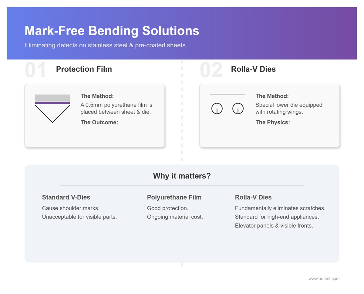
- Mark-free bending: the ultimate solution for visible parts For brushed stainless steel or pre-coated sheets, the shoulder marks left by conventional V-dies are unacceptable quality defects.
- Polyurethane protection film: Placing a roughly 0.5 mm thick high-strength polyurethane film between the sheet and the lower die completely isolates metal-to-metal contact, at the expense of some consumable cost.
- Rolla-V dies: A special type of lower die equipped with rotating wings. During bending, the wings roll with the sheet, converting sliding friction into rolling friction. This fundamentally eliminates scratching and indentation and is standard equipment for high-end appliance fronts and elevator panels.

3.3 Key process parameters checklist (SOP essentials)
A robust SOP (Standard Operating Procedure) is more than a sequence of steps; it is a precise definition and lock-in of all critical physical parameters.
- Dwell time: the crucial seconds for relieving internal stress When the ram reaches bottom dead center (BDC), do not reverse immediately. Set a dwell of 0.1–1.0 seconds to allow the metal lattice to rearrange under plastic deformation and release some internal stress. This brief pause significantly stabilizes springback behavior. For stainless steel and aluminum alloys in particular, dwell time is the hidden hero behind consistent bend angles.
- Mute point / speed change point: balancing efficiency and safety This is the position where the ram switches from rapid approach speed to slow working speed.
- Setting guideline: Typically set 2–5 mm above the sheet surface.
- Impact: If this point is set too high, the ram switches into slow crawl too early, stretching the cycle time unnecessarily and crushing throughput. If it is set too low, the ram may hit the sheet at approach speed, causing machine vibration or even serious safety incidents. Dialing in this point precisely is a low‑cost way to boost OEE (Overall Equipment Effectiveness).
- Retraction Distance: Eliminating Wasted Stroke After the bend is complete, the ram doesn’t need to return to Top Dead Center every time. By programming a sensible retraction distance in the CNC (typically just enough for part removal, e.g., part height + 20 mm), you can dramatically cut non‑productive stroke time. Over thousands of repeated cycles, optimizing this single parameter can add up to hours of additional productive time.
Ⅳ. Practical Operating Workflow: Execution Guide for Zero‑Defect Production
In modern precision sheet metal manufacturing, “zero defects” is no longer just a marketing slogan—it is an engineering target that can be achieved through rigorous process control. The essence of air bending on a press brake is to lock unpredictable physical variables into a controlled process framework. The following high‑level execution guide has been validated through extensive shop‑floor experience.
4.1 The “Golden Three Questions” and Preparations Before Bending
Before pressing the start button, a skilled operator performs a pre‑bend check that rivals a pilot’s pre‑flight inspection. This is not only about safety; it is also about eliminating 90% of potential scrap risks.
Question 1: Drawing Review – Do we truly understand the design intent?
- Reverse‑checking the K‑factor: Do not blindly trust the default K‑factor in your CAD software. In air bending, the developed length is extremely sensitive to V‑die width. If the drawing calls for R2 but you use a V16 die (which produces a natural radius of about 2.6 mm), the K‑factor must be corrected; otherwise, the flat pattern length will be off by millimeters.
- Strategic planning of grain direction: For high‑strength steel or stainless steel, the rolling grain is like wood grain. The iron rule: bend lines should be as perpendicular to the grain direction as possible. If you are forced to bend parallel to the grain, you must significantly increase the V‑die opening (recommendation: from 8T up to 10T–12T) to prevent outer‑surface cracking.
- Collision simulation: Use offline programming software (such as Dr. ABE, CADMAN‑B) for 3D simulation to detect potential collisions between the part and the side frames, backgauge fingers, or upper‑tool clamps in advance. Crashing in the virtual world costs nothing; in the real world it is catastrophic.
Question 2: Sheet Preparation – Is the material condition under control?
- Burr orientation rule: The tiny burrs left by laser cutting or punching are die killers. Standard practice: always place the burr side on the inside of the bend (against the punch). This prevents sharp burrs from tearing into cracks under tension and protects the hardened burr edge from scratching the expensive die radius, extending die life by more than 30%.
- Thickness measurement (critical): In air bending, the angle is determined by ram penetration (Y‑value). If the sheet thickness tolerance is ±0.1 mm, using the same Y‑value can produce angle deviations of 1°–2°. Advanced practice: Before each new batch goes into production, use a micrometer to measure thickness at multiple points, then enter the average value into the CNC so the control can automatically compensate the depth.
Question 3: First‑Article Trial – It’s more than just checking the angle The first‑article inspection (FAI) is not only to confirm “pass/fail”; it is also a critical data‑collection step.
- Verify developed length: Measure both sides and the overall length of the first piece and work backwards to confirm whether the actual K‑factor is correct.
- Lock in the springback rate: The first part is your litmus test for material springback. Record the deviation between the CNC’s target angle and the actual formed angle, then write this correction value back into the control to ensure consistency throughout mass production.
4.2 The Two Major Accuracy “Roadblocks” and How to Overcome Them
Even with perfect parameter settings, two physical challenges will still surface during production. Solving them is what separates an average operator from a true process expert.
Roadblock 1: Angle variation along the length (larger angle in the middle)
- Root cause: deflection. When tens of tons of force are applied at both ends by the hydraulic cylinders, the ram and bed undergo slight elastic bowing (the opening is larger in the middle). This means the sheet is pressed deeper at the ends and shallower in the center, creating a “banana‑shaped” angle error.
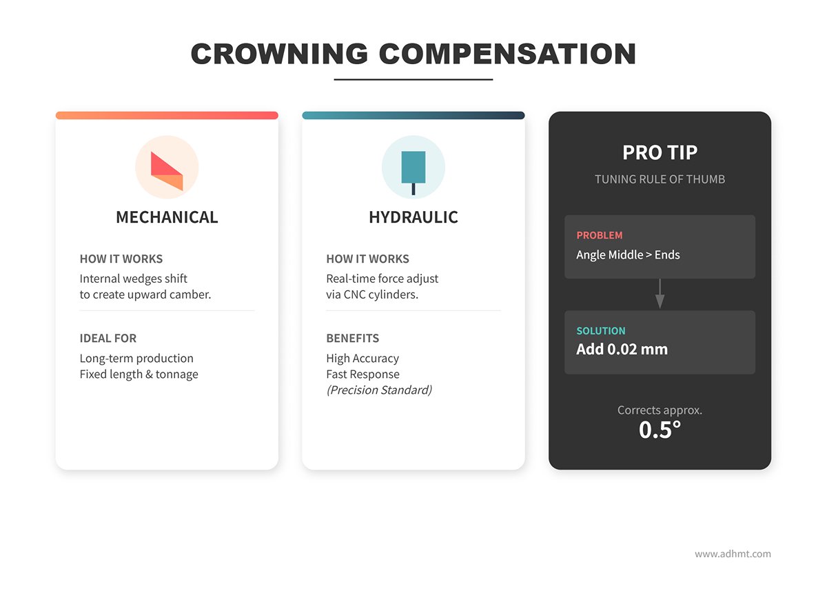
- Precise remedy: crowning compensation
- Mechanical crowning: A set of wedges inside the bed shift relative to each other to create an upward camber that mechanically offsets machine deflection. Best suited for long‑term production with relatively fixed lengths and tonnage.
- Hydraulic crowning: A series of hydraulic cylinders under CNC control adjust the compensation force in real time based on actual tonnage. It offers higher accuracy and faster response and is standard for high‑precision bending. Tuning tip: If the angle in the middle is larger than at the ends, increasing crowning by 0.02 mm typically corrects about 0.5° of deviation (depending on V‑die width).
Roadblock 2: Angle drift between batches
- Root cause: material variability. Between different heats from the same mill—and even across different areas of the same sheet—there are small variations in yield strength and thickness. These fluctuations directly change the amount of springback, causing a fixed CNC program to go out of tolerance.
- Ultimate remedy: adaptive bending system (LAMS)
- Integrate a Laser Angle Measurement System. During bending, lasers scan the flanges on both sides of the part in real time, and the CNC continuously calculates the true angle.
- Closed‑loop control logic: If the system detects that the angle is out of spec due to springback, it will, within the same stroke, automatically command the ram to move slightly deeper until the laser reading confirms the target angle is reached. This effectively eliminates the impact of material variation and achieves “first‑piece good, every piece on target.”
4.3 Advanced Techniques for Complex Scenarios
When dealing with non‑standard geometries, you need strategies that go beyond conventional thinking.
- Sequencing logic for multi‑stage bending
- Follow the principle of “inside‑out, small‑to‑large.” Prioritize internal features and short flanges, because once formed, they are the most likely to interfere with the tooling in later steps.
- Establish reference surfaces: Ensure that every bend has a reliable flat surface firmly against the backgauge fingers. If you must locate from a bent edge, use special notched fingers or custom fixtures.
- Closed profiles and interference avoidance
- Offset dies: For Z‑shaped parts where two bends are extremely close (less than the minimum V‑die spacing), an offset die allows you to form both bends in a single hit, boosting both efficiency and accuracy.
- Window bending: When forming closed square tubes or box sections, use a high‑neck gooseneck punch or segmented tooling to create a “window” for flanges that are already bent up, preventing them from colliding with the punch body.
- Tapered bending
- This is where CNC air bending really shows off its capabilities. By controlling the left and right hydraulic cylinders (Y1 and Y2 axes) to reach different bottom dead points, you can intentionally tilt the ram.
- Applications: Forming funnels, tapered light poles, or special profiles with gradually changing angles. Note: This operation must be kept strictly within the machine’s allowable tilt tolerance; otherwise, the ram guides can be damaged very easily.
Ⅴ. Troubleshooting and Quality Optimization
On a precision sheet metal production floor, troubleshooting is not just about fixing problems; it is also an opportunity to deepen your understanding of the underlying physics. Most bending defects are not random—they are the inevitable result of an imbalance between machine rigidity, material properties, and process parameters. This chapter takes a “pathology analysis” approach to break down the stubborn issues that often frustrate engineers.
5.1 Pathology Analysis and Repair Matrix for Typical Defects
Simply tweaking the depth rarely addresses the root cause of a defective part. We need to work backward from the visible symptoms to the physical causes, then develop a systematic correction plan.
| Defect Symptom | Root Cause (Physical Pathology) | Corrective “Treatment” |
|---|---|---|
| Canoeing (Phenomenon: After bending a long part, the middle angle is larger and the ends are smaller; viewed from the side, it looks like the curve of a boat hull.) | Machine deflection Under tens of tons of load, the ram and bed undergo slight elastic bowing. This makes the actual penetration depth at the center smaller than at the ends, so after springback the center angle becomes larger. The wider the V-opening, the deeper the ram must penetrate, which further amplifies this effect. | 1. Enable/calibrate crowning compensation: This is the only fundamental cure. Adjust the hydraulic or mechanical crowning so the middle of the bed is intentionally raised to offset the load-induced deflection. 2. Use a narrower V-opening: As long as the material allows, choose a smaller V-opening to reduce the required penetration depth and lower sensitivity to deflection. |
| Orange Peel (Phenomenon: The outer surface at the bend radius becomes rough, showing an orange-skin texture.) | Uncontrolled grain deformation When the inside bend radius is too small (R < 0.5T), the tensile strain on the outer surface is too high. Metal grains undergo severe slip and rotation, which manifests macroscopically as a rough surface. In essence, the material’s plastic deformation is pushed close to its limit. | 1. Increase the V-opening: Follow the “natural radius rule” and increase the V-opening (for example, from 6T to 8T or 10T) to obtain a larger natural inside radius and reduce tensile strain. 2. Optimize material selection: Use sheet with finer grain size, and verify that the upstream annealing process meets specification. |
| Cracking at the Bend (Phenomenon: Micro-cracks or complete fracture on the outer side of the bend.) | Tensile stress > elongation limit The bend radius is smaller than the material’s “minimum bend radius.” In addition, if the bend line is parallel to the rolling direction (grain direction), the grain boundaries are much more likely to tear. | 1. Bend perpendicular to the grain: Adjust nesting so the bend line is perpendicular to the rolling direction (best) or at a 45° angle. 2. Increase the radius: Use a larger V-opening or a punch with a larger nose radius. 3. Modify the material: For high-strength aluminum alloys and similar materials, perform local annealing around the bend area, or switch to a grade with higher elongation. |
| Ends tight, middle loose (angle tighter at both ends, more open in the middle) | Insufficient crowning compensation This is essentially the “canoeing” effect showing up in angle form. It indicates that the current crowning setting cannot fully offset the actual physical deflection. | 1. Dynamically increase crowning: In the CNC system, gradually increase the crowning value until the angle is consistent along the full length. 2. Shimming: For older machines without automatic crowning, place 0.1–0.3 mm paper or copper shims under the central region of the lower die holder to create manual compensation. |
5.2 Frequently Asked Troubleshooting Questions (FAQ)
Q1: Why do I get a good angle during first-piece setup in the morning, but the angle drifts during mass production in the afternoon even with the same program and tooling?
- Root cause: The thermal stability of the hydraulic oil.
- In-depth explanation: A press brake is driven by a hydraulic system. When started cold, the hydraulic oil has higher viscosity and the system responds more sluggishly. As continuous production heats the oil (ideal range: 30–55°C), the viscosity drops, and the ram’s bottom dead point begins to drift by microns. In air bending, a depth drift of just 0.05 mm can cause about 1° of angle deviation.
- Countermeasure: Implement a strict warm-up cycle—run the ram through idle strokes for 10–15 minutes before production. High-end machines should be equipped with oil cooling systems or CNC controls that offer temperature compensation.
Q2: Why do long, narrow parts (such as light troughs or side panels) twist after bending?
- Root cause: Residual stress release + reference misalignment.
- In-depth explanation:
- Internal cause: During rolling and slitting, the sheet accumulates significant internal stress. Bending breaks the original equilibrium, and the release of this stress makes the part twist like a pretzel.
- External cause: The backgauge is not parallel to the bend line. If the line formed by the gauge fingers is skewed, the part is already misaligned when it is positioned, and this geometric error grows dramatically with part length.
- Countermeasure: First, calibrate the parallelism of the backgauge (R axis to X axis). For internal material stress, try reducing bending speed, or use a leveling machine to relieve stress before bending.
Q3: I want to fine-tune the inside radius without changing tooling. Is that possible with air bending?
- Root cause: Misunderstanding of air bending mechanics.
- In-depth explanation: In air bending, the inside radius (Ir) is determined primarily by the V-opening width (Ir≈V/6), not by the punch tip radius or penetration depth. Changing the ram depth (Y-axis) only changes the bend angle; its influence on the inside radius is negligible.
- Countermeasure: If you must change the inside radius, changing the V-opening width is the only effective physical lever. To increase the radius, switch to a wider V; to decrease it, switch to a narrower V.
5.3 Preventive Maintenance for Equipment and Tooling
Process parameters only make sense when machine accuracy is under control. Preventive maintenance is the foundation for maintaining a high Cpk (process capability index).
- Monitoring die wear: Keep an eye on the “shoulders” The two shoulder radii at the edges of the lower die’s V-opening are the most highly stressed areas. Under long-term, high-frequency use, these shoulders wear, the radius grows, and in severe cases they may even collapse.
- Consequences: Worn shoulders increase the tonnage required (due to changing friction conditions) and act like a dull blade, leaving heavy scratches on the material surface and even causing angle instability.
- Action: Regularly perform visual inspections of shoulder surface finish. For precision work, measure shoulder radius consistency at least once per quarter.
- Calibration intervals: Fighting mechanical drift
- Backgauge calibration: Use a dial indicator to verify the repeatability of the back fingers (X-axis) and the parallelism between the left and right fingers. Recommended interval: once a month, or immediately after any collision incident.
- Ram parallelism: This is the key health indicator of a press brake. The left and right hydraulic cylinders on the ram must stay synchronized within microns. If you find that the left and right angles can never be leveled, or the machine starts making unusual noises, use a laser interferometer or precision level to recalibrate the parallelism between the ram and the bed. Recommended interval: one professional calibration per year.
Ⅵ. Appendix & Toolkit (Actionable Toolkit)
If the theories and strategies in the previous chapters are your navigation charts, this chapter is the Swiss Army knife in your backpack. On a fast-paced shop floor, nobody has time to re-derive formulas or recall parameters from memory. To truly implement the concept of precision “air bending,” you need a set of practical tools you can use straight away.
The following resources have been refined and standardized to help you rapidly build a shop- or enterprise-level process specification library.
6.1 [Quick Reference] Core Data Table for Air Bending Tonnage and V-Die Selection
Before every bend, confirming that the “required tonnage” is within the machine’s safe capacity is a non‑negotiable red line. The table below is based on a tensile strength of $420 MPa$ (standard mild carbon steel).
💡 Expert tips:
- Stainless steel correction: Multiply the table tonnage by $\times 1.5$.
- Aluminum alloy correction: Multiply the table tonnage by $\times 0.5$.
- Safety margin: Never run your machine at full rated load. For long-term operation, keep the working load within 80% of the nominal tonnage.
| Sheet thickness t (mm) | Recommended V opening (mm) | Minimum flange length b (mm) | Inside radius Ir (mm) | Required tonnage per meter (Ton/m) |
|---|---|---|---|---|
| 1.0 | 6 | 4.5 | 1.0 | 7 |
| 1.5 | 10 | 7.0 | 1.6 | 11 |
| 2.0 | 16 | 11.0 | 2.6 | 14 |
| 3.0 | 24 | 17.0 | 4.0 | 22 |
| 4.0 | 32 | 22.5 | 5.3 | 29 |
| 5.0 | 40 | 28.0 | 6.6 | 36 |
| 6.0 | 50 | 35.0 | 8.3 | 42 |
| 8.0 | 63 | 45.0 | 10.5 | 58 |
| 10.0 | 80 | 56.0 | 13.3 | 72 |
| 12.0 | 100 | 70.0 | 16.6 | 84 |
(Note: The above values are estimated from standard air-bending formulas and are for reference only. Actual numbers must be checked against the load capacity of your tooling.)
6.2 [Reference Chart] Typical K-Factor Values for Sheet Metal Unfolding
In air bending, the K-factor varies with the V-die opening. The following data is based on standard air-bending conditions (inside radius Ir≈V/6) and is suitable for flat pattern calculations in SolidWorks, ProE, and similar software.
| Material type | Mild Steel | Stainless Steel (SS304) | Aluminum Alloy (AL5052) |
|---|---|---|---|
| Theoretical K-factor range | 0.42 - 0.45 | 0.45 - 0.50 | 0.40 - 0.45 |
| R/T < 1 (small radius) | 0.38 | 0.42 | 0.35 |
| R/T = 1 (standard) | 0.42 | 0.45 | 0.41 |
| R/T > 2 (large radius) | 0.48 | 0.50 | 0.45 |
⚠️ Warning:
- When you change the V-die opening, the natural inside radius (Ir) will change accordingly, and you must update the K-factor in your CAD software at the same time. Otherwise, your flat pattern lengths will be significantly wrong.
- Each factory should build its own measured database of “bend deduction” values based on its specific material suppliers. This is more accurate than relying solely on theoretical K-factors.

Closing note: The art of manufacturing lies in controlling variables
Air bending is more than just a metal forming technique; it is an elegant interplay of physics, geometry, and materials science. From grasping the fundamental logic that “depth defines angle,” to mastering springback control models, to enforcing rigorous SOPs, every step reflects a deep respect for precision manufacturing.
This guide is meant to serve as a beacon in your shop. But remember, the best process parameters are never just the numbers printed in a book—they are the data assets you build up over countless trials, measurements, and optimizations on the floor. Now, armed with these tools, go and redefine the bending standards in your factory.
Ⅶ. FAQs
1. What factors influence the precision of air bending on a press brake?
Several crucial factors affect the precision of air bending:
- Material Properties: Variations in material type, thickness, and composition can lead to differences in how the material behaves during bending, including the degree of springback.
- Tools and Dies: The condition and selection of punches and dies directly influence bend accuracy. Precision-ground tools and appropriately matched die openings are essential.
- Machine Calibration: Precise machine calibration, including proper adjustment of the ram and backgauge, is necessary to maintain consistent bend angles and dimensions.
- Operator Skill: Experienced operators are adept at making fine adjustments based on previous bends and real-time feedback, enhancing overall precision.
- CNC Control Systems: Advanced CNC systems offer greater precision through automated adjustments and real-time monitoring, minimizing human error.
2. How does air bending differ from bottoming and coining?
Air bending, bottoming, and coining are distinct in their approaches and outcomes:
- Air Bending: The punch presses the sheet metal into a V-die without full contact at the bottom, relying on material elasticity for the final bend. It requires less force and offers flexibility at every bend angle.
- Bottoming: Full contact with the punch and the die, creating a 'bottomed-out' bend. This method ensures higher angle accuracy but demands greater force and has less versatility in varying bend angles.
- Coining: This process involves the punch embedding into the material, exceeding the yield point and resulting in permanent deformation. Coining provides extremely precise bends with minimal springback but at the cost of high force requirements and tool wear.
3. What types of materials can be used in press brake air bending?
Press brake air bending is versatile and can accommodate a wide range of materials, including:
- Steel (Mild, Stainless, and High-Strength Alloy Steels): Commonly used due to their strength and ductility.
- Aluminum: Offers good formability and is preferred for its lightweight properties.
- Brass and Copper: Utilized in applications requiring good conductivity and aesthetics.
- Titanium and Nickel Alloys: Selected for their high strength-to-weight ratio and corrosion resistance, often in aerospace and chemical industries.
Different materials may require tailored tooling and machine parameters, which are typically outlined in product brochures; for more specific application support, you can also contact us to match the right press brake solution to your material portfolio.