Knowing how to correctly use DXF file on press brake is the essential skill separating basic operation from true automated manufacturing. A DXF is not just a drawing; it's the digital DNA for your component, dictating every outcome. Getting it right means seamless production. Getting it wrong guarantees errors, waste, and downtime.
This guide provides a complete, professional framework for mastering the DXF workflow. We will cover everything from creating a "machine-friendly" design and navigating intelligent controller imports to leveraging automated programming and troubleshooting common failures. This is your definitive resource for turning DXF files into a powerful tool for flawless, efficient press brake production.
I. Rethinking the Basics: Why DXF Is the Lifeline of Modern Bending
In the context of modern precision sheet metal fabrication, if we treat DXF (Drawing Exchange Format) as nothing more than an electronic “drawing,” we are planting the seeds for production failures from the very beginning.
A DXF file is not a static picture. It is a dynamic stream of data packed with precise instructions, bridging virtual design and physical reality. Beyond pure geometry, it embeds material science and process logic. Calling it the “lifeline” of modern bending is no exaggeration: it fundamentally dictates the execution logic of all downstream automation equipment and sets the upper limit of finished-part accuracy.
1.1 The True Nature of the Digital Bridge
At its core, DXF is a universal, vector-based carrier of geometric data. Think of it as a highly standardized “digital shipping container” that packages the engineer’s 2D flat pattern intent from the CAD system into a mathematical language that virtually all manufacturing equipment—from laser cutters to CNC press brakes—can read without loss.
- Beyond “images”: it carries “instructions” Unlike raster images such as JPG or PNG, which are made of pixels, a DXF file contains no pixels at all. It stores mathematical descriptions of geometric entities like lines, arcs, and polylines. For example, a straight line in DXF is defined by the exact X/Y coordinates of its start and end points. This means that whether you zoom in by a factor of 1,000 or 10,000, the geometric accuracy remains absolutely unchanged. For CNC machines that aim for micron-level precision, this is irreplaceable: the machine needs commands like “move to coordinate (100.5, 200.0),” not a vague visual outline.
- The encoded outcome of bending theory and process logic Here’s a deeper truth that many practitioners overlook: a well-prepared sheet metal DXF is itself the calculated result of complex bending theory. Before exporting the DXF, the engineer must account for material thickness, material type (e.g., stainless steel vs. aluminum), and selected die opening (V-opening), then compute the correct bend deduction or apply the correct K-factor. So when the shop floor receives a DXF file, they are not just getting a profile; they are receiving a pre-processed process package that already encodes how the material stretches, how the bend radius forms, and more. If the original DXF was not calculated using the actual shop tooling and parameters, no matter how skilled the operator, the finished bent parts will not meet the intended dimensions.
1.2 A Deeper Look: How Machines Actually “Read” Your Drawing
CNC equipment does not “see” drawings the way humans do; it has no visual perception. It cannot intuitively understand what a line represents. Instead, it parses data streams and converts DXF entities into a series of machine motion commands (such as G-code). In bending, this “reading” process becomes particularly complex and critical.
- Layers as semantics: how the machine classifies actions To the machine, layers in a DXF are not just different colors; they are categories of machining instructions.
- Cutting instructions: When the machine reads a layer like “CUT,” it drives the laser head at full power to perform through-cutting.
- Auxiliary instructions: When it reads a “MARK” or “ETCH” layer, it switches to low-power etching to create visible bend reference lines or part IDs on the surface.
- Bending instructions: This is where it becomes critical. Modern offline programming systems scan designated layers (such as “BEND-UP” or “BEND-DOWN”) and interpret those entities as “bend lines.” If you do not follow these layer conventions, the software cannot distinguish between cut contours and bend locations.
- From 2D outlines to a 3D “script”: deep interpretation Modern high-end press brakes and their offline programming software (e.g., ALMACAM Bend, Metalix MBend) go far beyond simply reading coordinates from a DXF. They perform a full-dimensional virtual rehearsal:
- Data fusion: The software links the 2D flat DXF to the 3D STEP model to verify consistency between the “flat” and the “formed” part.
- Reverse simulation: Using the bend line locations in the DXF, it simulates, in a virtual environment, how the sheet will be lifted and formed step by step.
- Interference prediction: This is the core value of how the machine “reads.” It checks in the virtual space whether any bend step will collide with the punch, the backgauge, or the machine frame.
The implication is clear: the press brake does not directly execute the DXF drawing. It executes an optimized bending “script” generated from the DXF and validated by strict logical checks. DXF is the foundation of this script. If that foundation contains open contours, duplicate entities, or scaling errors, the automation script may fail to generate—or worse, generate incorrect commands—leading to costly scrap or even machine damage. Mastering proper DXF preparation is therefore the first step toward error-free bending.
II. Fixing Problems at the Source: Building a “Machine-Friendly” DXF Standard

“Garbage In, Garbage Out” is a hard rule in CAM (Computer-Aided Manufacturing). A DXF file full of redundant data, geometric errors, or unclear intent is the root cause of bending mistakes, low efficiency, and expensive rework. That is why rigorous “source control” before the file leaves the design department is not just a technical nicety; it is the dividing line between traditional manufacturing and truly automated bending.
2.1 The “Minimalist” Seven-Step File Cleaning Method
A truly “machine-friendly” DXF must first be “clean.” The core principle is to strip away everything that could confuse the machine and keep only the pure geometric machining instructions. Any extra element might be misinterpreted as a cutting path or trigger an error in the CAM software. Below is a field-tested standard cleaning workflow:
- Remove all non-geometric information: Before exporting the DXF, delete every dimension, title block, note, section hatch, and construction/centerline. The machine only needs to know “where the contour is,” not to read human-oriented annotations.
- Run the
OVERKILLorPURGEcommand: This is a crucial but often overlooked step in AutoCAD and similar tools. These commands automatically search for and remove overlapping segments, duplicate entities, and zero-length lines. Overlapping lines can cause the laser to cut the same path twice, wasting time and overheating the edge, which in turn affects edge quality and the accuracy of backgauge positioning for subsequent bending. - Close and connect all contours: Make sure every external contour of the part is drawn as a continuous, closed polyline. Even a tiny gap in the contour (as small as 0.01 mm) can cause the CAM software to treat it as an open shape, which may prevent it from generating correct inside/outside cutting paths.
- Fully explode all blocks: Break down every complex object defined as a “block” or “group” into the most basic geometric elements (lines and arcs). Many entry-level CAM systems cannot interpret nested block references, so you must “explode” them to ensure full compatibility.
- Convert spline curves to line/arc segments: Splines are smooth curves defined by complex mathematical functions, and some older or basic controllers cannot read them directly. You must convert splines into polylines approximated by many small line and arc segments to guarantee broad compatibility.
- Strictly enforce a 1:1 scale: When exporting, the geometry must be saved at true size (1:1). Any scaled view (for example, a 1:10 drawing view) will result in scrap parts because the manufactured dimensions will be wrong.
- Save to an older DXF version: To maximize compatibility with CAM software and controllers from different generations, save the DXF file in an earlier, widely supported format (such as AutoCAD 2000/R12 DXF). This significantly reduces “unrecognized file” errors caused by newer header formats.
2.2 Semantic Layer Management System
This is the key step in upgrading from a merely “clean” file to an “intelligent” one. By establishing a standardized layer system with clear semantics, we enable the machine to directly “understand” the designer’s intent, paving the way for highly automated programming.
A professional sheet-metal DXF layer structure should have clearly defined functional meanings. A recommended reference standard is as follows:
| Layer Name | Color | Linetype | Semantics/Machine Instruction |
|---|---|---|---|
| CUT-OUTLINE | White | Continuous | External contour cut: the outermost boundary of the part. |
| CUT-INTERNAL | Red | Continuous | Internal cutouts: all holes or openings inside the part. |
| BEND-UP | Blue | Dashed | Upward bend line: indicates this line is bent upwards; the software will use it to select the punch. |
| BEND-DOWN | Yellow | Dashed | Downward bend line: indicates this line is bent downwards. |
| ETCH-MARK | Green | Continuous | Surface etching/marking: used for part numbers or auxiliary marks; the machine uses low-power laser etching instead of full cutting. |
Deep insight: When offline programming software (such as ALMACAM or Metalix) imports a DXF file that follows this “semantic layer” convention, it can perform highly automated processing. The software automatically identifies bend lines and their directions without manual definition. Based on this information, it can autonomously plan the bending sequence, select tools, and run collision checks. In essence, this layer system is the basic grammar that makes “lights-out” smart manufacturing possible.
2.3 Flat Pattern Calculation and Material Matching
The most frequently misunderstood source-control step—and a major cause of scrap—is the dimensional accuracy of the DXF flat pattern.
- A DXF flat pattern is a calculated result, not a simple geometric projection The 2D flat pattern of a sheet-metal part is absolutely not equal to the sum of the individual faces of the 3D model. During bending, the outer fibers are stretched, the inner fibers are compressed, and the neutral axis shifts. Therefore, the developed length in the DXF must be computed using an accurate bend compensation method (such as K-factor, bend deduction BD, or bend allowance BA).
- The hidden risk of “what you see is NOT what you get” The K-factor or bend deduction values used by the designer in CAD must be strictly aligned with the actual sheet thickness, material grade (e.g., SS304 vs. AL5052), and V-die opening width (V-opening) used in production.
- Typical pitfall: Suppose the designer generates the DXF using parameters for “1.5 mm thick steel with a V12 lower die”, but on the shop floor the operator switches to a V8 die to achieve a smaller inside radius. The final formed part dimensions will then inevitably be wrong, because changing the V-opening directly alters the required bend compensation.
- Best-practice strategies for root-cause control:
- Build a unified process database: The design and production teams must agree—via a formal technical specification—on a standardized bend compensation database. The optimal approach is for the production side to derive a precise K-factor table from real trial bends with existing tooling, and then supply it to the design team.
- Embed key parameters in the file name: When delivering a DXF, clearly indicate the basis of the calculation in the file name. For example:
Part-A_T1.5mm_SS304_V12.dxf. This allows the operator to immediately verify that the process parameters match. - Double deliverables: The industry gold standard is to deliver both the DXF (2D flat pattern) and the STEP (3D solid model). Then, if the shop must change the process (e.g., use a different V-die), the offline programming software can read the STEP model and recalculate the flat pattern using the new tooling parameters, eliminating dimensional errors caused by process changes at the source.

By applying these three layers of source control, the DXF file ceases to be just a drawing; it becomes a “digital process card” carrying precise geometry, clear manufacturing intent, and correct process parameters, providing a solid foundation for all downstream automation steps.
III. Intelligent Import: Practical Workflows and Mapping Settings for Mainstream Controllers
A perfect DXF file is only the “script”. To turn it into a precise “performance”, you still need a director—the CNC controller—to interpret and rehearse it in depth. Intelligent import is far more than a file transfer; it is the process in which the controller reads, parses, and jointly validates the “script” with the operator. At this stage, the data first collides and interacts with real-world constraints such as tooling, tonnage, and machine stroke.
3.1 System Configuration Before Import
Before your finger ever touches the “Import” button, you must ensure that the controller’s “brain” is preloaded with a knowledge base that exactly reflects the reality of your shop floor. If this fundamental configuration is missing, the controller will be at a loss when faced with a DXF file—and may even generate incorrect instructions.
- Digital twin of the Tool Library This is the most basic step—and the one that most often goes wrong. You must preload the controller’s tool library with the exact geometric data for every single punch and die available on the shop floor, including height, angle, tip radius, V-opening width, and maximum allowable tonnage. Each tool set must be assigned a unique ID so the digital model matches the physical tool one-to-one. Without this library, the controller’s Auto-Tooling function is like trying to cook without ingredients.
- Defining physical properties in the Material Library The controller needs to know what it is actually bending. In the material library, you should not only define the material name (such as SS304, AL5052), but also accurately enter its tensile strength and elastic modulus. These parameters are the fundamental physical basis for calculating bending force, predicting springback, and determining precise flat patterns.
- Deep dive: The value of the built‑in compensation database High-end controllers (such as the DELEM DA-60 series or Cybelec NexT) store far more than simple dimensions. They include an empirical bend-compensation database derived from tens of thousands of test bends performed by the controller manufacturer. This database records the actual flow characteristics of different materials on specific V-dies. Compared with generic K-factor formulas used in CAD, relying on the controller’s internal database for final calculations usually delivers significantly better angle accuracy.
3.2 Step-by-step breakdown of the core import workflow (using DELEM / NexT as examples)
While different controller brands have very different user interfaces, their core logic is highly consistent: they guide the user in converting 2D lines into a fully process-aware 3D bending program.
- DELEM controllers (DA-Touch series as an example)
- Enter drawing mode: From the main menu, navigate to “Products,” select “New,” and switch to “2D Drawing” mode.
- DXF loading and scale verification: Import the file via USB or network. Critical step: once the geometry is displayed, always use the on-screen “Measure” tool to pick any two points and check whether the reported distance matches the drawing dimension. This is your only real safeguard against parts being scaled up or down by a factor of 25.4 due to imperial/metric unit mismatches.
- Property definition: The system will prompt you to enter the sheet thickness and material type. These inputs directly define the reference values for bending force calculations.
- Feature recognition: The system attempts to automatically recognize the outer contour and bend lines. If DXF entities are not fully closed, the system will throw an error at this stage. You then need to use the controller’s “Connect” function to repair tiny gaps or breaks.
- Cybelec NexT controller
- Launch the CAD import wizard: NexT’s interface is more visually driven; simply click “Import DXF.”
- Layer mapping: This is the system’s standout feature. If your DXF follows the earlier “semantic layer” conventions, you only need to map DXF layer names (such as
BEND-UP) to specific controller functions. In other words, you tell the system: “All lines on layerBEND-UPare front-side bends.” This instantly assigns properties to complex parts and boosts setup efficiency by several times. - Geometry cleanup and 3D preview: The system automatically removes stray entities and, based on the recognized features, generates an initial 3D bending model for operator review and confirmation.

3.3 The “second handshake” on critical parameters
This is the most important stage of human–machine interaction between “imported geometry” and “executable code.” We call it the “second handshake,” meaning the final alignment between the operator’s experience and the machine’s algorithms.
- Confirming bend-line properties Automatic recognition is never 100% reliable. The operator must review each identified bend line and verify that the bend angle (e.g., 90° vs 135°) and bend direction (upward/downward) are correct. For special processes such as hemming, the operator will usually need to manually assign dedicated process attributes.
- Validating physical consistency of tool assignment Based on the bend angle and sheet thickness, the controller will propose a theoretically optimal tool combination. At this point, the operator must intervene and perform a crucial manual check: confirm that the suggested tools match what is actually mounted on the machine. If the system recommends a V12 die but there is a V10 die installed, you must override the system’s setting to match the real setup, or you risk severe angle deviations or even a crash.
- 3D simulation of the bending sequence (The Digital Rehearsal) This is the final safeguard before generating the program. The controller computes and plays back the entire bending process as a 3D animation on screen.
- Collision detection: Watch the animation carefully to see whether the part will collide with the side frames, upper beam, or backgauge fingers during any flipping or reorientation.
- Ergonomic review: The algorithm optimizes for the shortest motion path, but it may generate moves that a human operator simply cannot perform safely or comfortably. Experienced technicians will adjust the bend sequence at this stage to minimize the number of flips for large sheets and keep operations ergonomic.
Only when these three handshakes—line properties, tool matching, and simulation—have all been verified does the controller compile everything into the final G-code. This workflow perfectly illustrates how modern manufacturing blends human and machine intelligence: the machine handles computation and precision, while the human provides logical judgment and safety oversight.
IV. Process programming: DXF-based automation strategies and simulation
Once you have a “machine-friendly” DXF file and a properly configured controller, you enter the central nervous system of modern bending—process programming. At this stage, the geometric data in the DXF is no longer just a collection of lines; it is transformed into concrete physical motions.
Modern offline programming software acts as a “virtual process engineer,” using the precise information from the DXF to automatically perform complex planning tasks that used to take experienced technicians hours or even days to complete.
4.1 Intelligent tool selection (Auto-Tooling)
Intelligent tool selection is far more than simply “picking a punch and die.” It is best understood as the software searching for an optimal solution under a web of constraints. Think of it as a tooling expert with unlimited knowledge that, based on thickness, material, and bend angles extracted from the DXF, configures the most suitable tool combination for each bend.
- Decision logic driven by physical constraints When the software reads a bending command from the DXF (for example: bend 1.5 mm stainless steel to 90°), its internal algorithm runs through a rigorous filtering process:
- Locking in V-opening width: The software first applies the “safe V-opening rule” (typically set to 6–8 times the material thickness). For a 1.5 mm sheet, it will preferentially lock in dies with V8, V10, or V12 openings from the database, eliminating the risk of material cracking or excessive indentation from a physics standpoint.
- Predictive geometric interference check: This is the heart of intelligent matching. The software calculates the punch height and profile (for example, straight punch or gooseneck punch) to ensure that, when forming deep U-shapes or closed box structures, the tooling itself will not collide with already formed edges of the part.
- Tonnage safety threshold: Based on the bend length and material tensile strength extracted from the DXF, the software automatically calculates the required forming force and filters out any tools whose rated load capacity is insufficient, preventing damage to expensive tooling.
- Deeper insight: the value of global optimization
The real power of Auto-Tooling lies in its global optimization capability. A typical operator may be used to picking the most familiar tool for each individual bend, whereas the algorithm’s goal is to find a single unified tool set that covers all bends on the part. By maximizing the chances of running the entire job with no mid-process tool changes, non-productive time (downtime) can be dramatically reduced—this is the most direct way to boost overall efficiency per part.
4.2 Bend sequence optimization algorithm (Sequencing)
Once the tooling is selected, the software faces an extremely challenging “3D traveling salesman problem”: In what sequence should all bends be performed to ensure zero collisions while minimizing the number of part flips for the operator?

- How the algorithm “thinks”
In a virtual 3D environment, the software explores dozens or even hundreds of possible bending paths, then applies a rigorous scoring system to choose the best sequence:- Collision detection (absolute veto): This is the highest-priority rule. For every bend step, the software checks whether any part of the sheet will make physical contact with the punch, die, machine frame, or backgauge. Any sequence with potential collision risk is rejected outright.
- Operational convenience (efficiency weighting): Among all “safe” sequences, the software favors those with the fewest part flips and rotations. Every flip adds auxiliary time and increases operator fatigue as well as the chance of human error.
- Process rule compliance: The algorithm embeds classic sheet metal best practices, such as “short sides before long sides” and “inside bends before outside bends,” to maintain part rigidity and stability throughout forming.
- Why a human-in-the-loop is essential
The sequence that is “mathematically optimal” is not always “ergonomically optimal.” The algorithm may consider flipping a 2-meter-long, 50 kg sheet acceptable, but in reality this can be unsafe and impractical for the operator. That’s why the most advanced programming workflows always include a manual fine-tuning stage. Experienced programmers review the simulation and adjust steps that, while theoretically valid, are awkward or unsafe on the shop floor—achieving a true synergy between machine intelligence and human experience.
4.3 3D simulation and offline programming (Offline Programming)
Offline programming (OLP) is the dividing line between a modern sheet metal factory and a traditional workshop. The core idea is to remove programming from the production floor and complete it in the office on a computer.
- Maximizing machine uptime
In a traditional setup, programming, trial bending, and adjustments are all done directly on the press brake, meaning the machine—an expensive asset—spends a large portion of each day sitting idle. Offline programming changes this completely: while the press brake is running part A at full speed, engineers in the office can simultaneously complete DXF import, programming, and simulation for parts B, C, and D. Once part A is done, the operator simply loads the next program and can start production immediately. This parallel workflow unlocks substantial extra capacity. - “Zero-cost trial and error” with a digital twin
3D simulation is the core of offline programming. It creates a “digital twin” environment that faithfully mirrors the physical shop floor.- Manufacturability verification: On-screen, you can clearly see the part being formed step by step, with any potential collisions highlighted. This lets you identify design flaws or process dead ends before any sheet metal is actually cut.
- Accurate quoting support: Simulation not only verifies feasibility; it also calculates the total production cycle time with high precision, including tool changes, bending, and flipping. This allows companies to move away from rough estimates and instead provide quotes based on precise, second-level data—competitive for the customer, yet still reliably profitable.
V. Shop-floor execution: from first-article approval to mass production
This is the “last mile” of the digital bending workflow, and it ultimately determines the final product quality. No matter how perfect the DXF preparation or how accurate the offline programming, any deviation during on-site execution can still lead to disastrous results.
Every step—from loading the program to running full-scale production—must therefore follow a standardized, verifiable, and rigorous process.
5.1 The three mandatory safety checks before running the job
Before pressing the “Start” button, the operator must perform a “three-point safety check,” just like a pilot going through a pre-flight checklist. This is the final physical safeguard against hardware damage, personal injury, and first-article failure.
Checking the “virtual–physical mapping” between program and tooling
- Identity verification: On the controller screen, first confirm that the loaded program name matches the part number and revision on the work order exactly. This may seem basic, but it is the only reliable way to prevent low-level mistakes like “bending part B using parameters for program A.”
- Physical tooling configuration: Call up the tooling setup list in the program and verify punch ID, die ID, and station positions one by one. High-end controllers display the exact length and position of each tool segment, and the on-machine installation must match this layout with millimeter-level accuracy.
- Deeper insight: A frequently overlooked but potentially catastrophic risk is the installation orientation of asymmetric tools. This is especially critical for non-symmetric gooseneck punches, where flipping the punch front-to-back will fundamentally change the interference zone. The operator must ensure that the physical orientation of the tooling is a 100% match with the 3D simulation, otherwise you can have a sequence that passes simulation but still results in a crash on the machine.
Tool clamping integrity and contact surface cleanliness
- Clamping confirmation: Whether using traditional bolt clamping or a modern hydraulic/pneumatic quick-clamping system, you must confirm that the tools are fully locked. A loose tool can shift or even be ejected under tens of tons of pressure, causing chipping, tool breakage, and scrapped parts.
- Micro-level cleaning: Use a clean industrial wipe to thoroughly clean the critical contact surfaces of the upper and lower dies (such as the punch tip and the shoulders of the V-opening). Tiny metal chips or thin oil films left from the previous batch are enough to shift the actual contact points and introduce bending angle errors of 0.5° or more.
Dry run and coordinate system calibration
- Dry run: Without placing any sheet material, reduce the ram speed and let the machine run through the entire bending program once with no load. Use sight and hearing to check whether the backgauge movement logic is correct, the ram approaches smoothly to the programmed depth, and whether there are any abnormal mechanical noises.
- Backgauge homing: Before the dry run, always perform a full homing or “reference point” routine for the backgauge. If the absolute coordinate system is not correctly established, every positioning move of the backgauge will be based on the wrong reference.
5.2 Standardized First Article Inspection (FAI) process
First Article Inspection (FAI) is not only the “birth certificate” for mass production, but also the final acceptance of the entire digital chain from design to DXF to programming to execution. A modern FAI process no longer focuses solely on “pass or fail”; it places equal emphasis on “deviation correction.”
Full-process simulated production
- Use a sheet from exactly the same material batch planned for mass production, and clearly mark it as the “first article.” Follow the bending sequence on the controller strictly. During the process, the operator should pay close attention to how the part feels in hand, whether flipping and handling match the simulation experience. If the part is very awkward to manipulate or potential safety risks are identified, this must be reported immediately so that the programming team can optimize how the DXF is processed.
High-precision, multi-dimensional measurement
- Geometric dimensions: Use a calibrated digital caliper to measure the length of all flange edges.
- Angle verification: Use a digital protractor or dedicated radius/angle gauges to measure all critical bend angles. For high-precision parts, it is recommended to use a laser angle measurement device, which offers far higher accuracy than traditional contact tools and can capture angle deviations invisible to the naked eye.
- Digital comparison: For parts with complex surfaces or multiple bends, modern shops often deploy portable CMMs (articulated arms) or 3D scanners. By comparing the scan data of the first article with the original CAD model in a full-color deviation map, issues such as twist, uneven springback, and other hidden defects become immediately obvious.
Key step: closing the loop on springback compensation
- No matter how accurate the offline programming calculations are, each batch of sheet material has slightly different mechanical properties (especially yield strength and hardness), so the actual springback almost always differs from the theoretical value by a few tenths of a degree.
- Data feedback mechanism: For example, the program target is 90°, but the measured angle on the first article is 90.3°. In this case, the operator does not need to modify the NC program. They only need to enter the actual measured value “90.3°” on the controller’s correction/offset page.
- Intelligent reverse compensation: After receiving this feedback, the controller automatically adjusts the Y-axis penetration depth based on its internal algorithm (typically a fine adjustment of around 0.05 mm), so that the second part already hits 90° precisely. This is the critical step that feeds real-world physical variation back into the digital brain and completes the control loop.
5.3 Process control and documentation
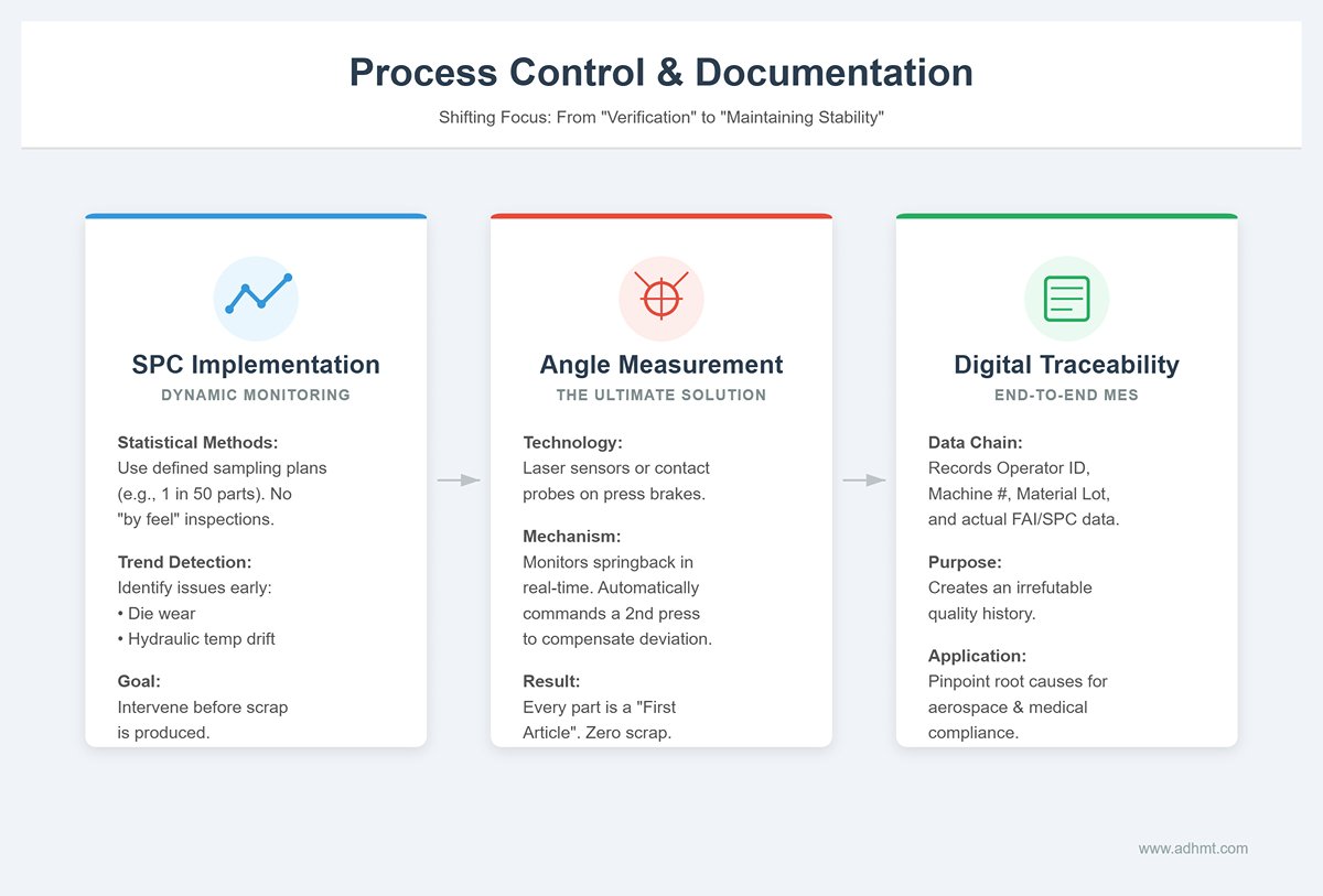
Once the first article passes, the focus of production shifts from “verification” to “maintaining stability.” During mass production, quality must be secured through sound statistical methods, not luck.
- Implement SPC for dynamic monitoring
Establish a clear Statistical Process Control (SPC) sampling plan, such as “after every 50 parts, randomly select one for full dimensional inspection.” Arbitrary, “by feel” sampling is strictly forbidden. By tracking measurement trends over time, you can detect potential issues in advance—such as bend angles slowly increasing due to die wear, or machine accuracy drifting as hydraulic oil temperature rises—and intervene before scrap is produced. - Deploy in-process angle measurement systems (the ultimate solution)
This is the key technology for “lights-out” or low-manning production. High-end press brakes equipped with in-process angle measurement systems (such as laser-based sensors or contact probes) can monitor the sheet’s springback angle during every single bend. If a deviation is detected (for example due to uneven sheet thickness), the system immediately commands a second pressing within the same cycle to compensate. In effect, every part is treated as a “first article”, with each bend validated and corrected in real time, eliminating scrap at the source. - End-to-end digital traceability
Modern Manufacturing Execution Systems (MES) record the complete data chain behind every conforming batch: operator ID, machine number, program version, production time, material heat/lot number, and actual measured data from FAI/SPC. This is not just for archiving; it builds an irrefutable quality traceability chain. If a customer later reports a quality issue, the factory can use this chain to pinpoint the true root cause—be it material, program, or operator error. In high-regulation industries such as aerospace and medical devices, this capability is fundamental to survival.
VI. Troubleshooting: A DXF Application Issue and Solution Library
Problems are inevitable when converting from digital design to physical product. What sets an efficient sheet metal team apart is not “never making mistakes,” but having the ability to diagnose and resolve issues quickly and accurately. We classify common DXF application problems into three core categories and dig into the technical logic behind them as well as their permanent fixes.
6.1 File import issues: eliminating “data islands”
These problems occur at the very beginning of the workflow and typically appear as the controller or offline programming software refusing to open the file, or the geometry looking completely wrong after opening. In most cases, the machine is not at fault—the root cause is a mismatch in data “dialects.”
- The truth behind “file not recognized”: version and encoding traps
When the controller reports “unsupported file format,” the most common cause is that the DXF version is too new. Designers often use the latest CAD releases (such as AutoCAD 2024), and the exported file structure includes new data blocks that older controllers simply cannot parse.- Solution: Establish a strict “save down” standard. During export, always force the file to AutoCAD 2000 DXF or R12 DXF format. While these versions are old, they strip out complex metadata and serve as the most universally compatible “common language” for CNC equipment. In addition, ensure the file is saved in ASCII rather than Binary format. Binary files are smaller, but their compatibility is dramatically worse.
- Scrambled geometry and “ghost lines”
If, after import, arcs turn into jagged polylines or mysterious shapes appear, the culprit is usually proxy entities or splines. Proxy entities are proprietary objects created by certain CAD add-ons that standard DXF definitions do not cover. Splines are mathematically complex curves, and many basic controllers can only approximate them as rough polylines.- Deep-clean export strategy: Before exporting, you must run the Explode command to break all blocks and proxy entities down into the most basic lines and arcs. For splines, convert them in CAD to high‑precision polylines, sacrificing editability in exchange for absolute machine readability. At the same time, carefully verify the unit settings during export to avoid having millimeters interpreted as inches, which would scale the geometry by a factor of 25.4.
6.2 Dimensional accuracy issues: eliminating the gap between “theory” and “reality”
This is the type of problem engineers find most frustrating: the DXF drawing looks flawless, but the dimensions of the first article (FAI) are consistently off. The root cause is usually not operator error, but a mismatch in the underlying calculation logic.
- Where 90% of deviations come from: mismatched process parameters
A classic example is a flange that ends up too short or too long after bending. This typically happens because the K‑factor (or bend deduction) used by the designer in CAD is just a theoretical value (such as the default 0.44), while the shop floor is using a different V‑die opening or a different batch of material in actual production.- Root-cause fix: Break down the wall between design and manufacturing. The production team should use the commonly used tooling and materials in the shop to build an accurate, empirically derived company‑level bend compensation database, then integrate it directly into the CAD software used for design. A more advanced approach is to adopt a Double Deliverable process, delivering the STEP model along with the drawings. This allows offline programming software to recalculate flat patterns based on the STEP model and the real shop‑floor tooling parameters, eliminating parameter mismatches at their source.
- The invisible killer behind unstable angles: material batch variation
If the program is set to 90°, but the actual bend ends up at 90.5° or 89.5°, and the results fluctuate even within the same batch, the culprit is often variation in material properties. Differences in hardness (tensile strength) between batches, or even across different areas of the same sheet, directly change the amount of springback.- Response strategy: Don’t rush to rewrite the program. First, use the controller’s angle correction function to feed the measured angle of the first piece back into the system and create a closed compensation loop. For high‑precision requirements, the only robust solution is to add an online angle measurement system (such as laser-based angle measurement) to monitor every bend in real time and apply re-pressing compensation as needed, fully mitigating the quality risks caused by inconsistent material behavior.
6.3 Process-logic issues: bridging the gap between the “virtual” and the “physical”
These failures are the most deceptive: the 3D simulation in offline software runs perfectly, but once the program hits the machine, you get collision alarms or extremely awkward operation on the shop floor.
- “Fake twins” and collision risk
When simulation passes but you still crash on the machine, the core reason is that your digital twin model is not a true reflection of reality. For example, the backgauge fingers in the software are modeled as standard components, while the actual machine is fitted with extended fingers; or auxiliary side supports mounted on the real machine were never modeled in the software at all.- Calibration actions: Regularly review and verify the machine and tooling libraries in the offline programming software. Any hardware change in the physical world—down to something as small as a thicker clamp—must be synchronized into the software model. Only when you achieve a 100% physical match can you trust your simulation results.
- The overlooked factor: gravity
When bending large thin sheets, simulation software usually treats the workpiece as a rigid body. In reality, the sheet will sag under its own weight. This deflection can cause the sheet edge to contact the backgauge or die rail earlier than expected during movement, triggering unanticipated collisions or surface scratches.- Solution: For parts like these, software algorithms alone are not enough. You must add manual expert review to anticipate sagging risks. On the physical side, equipping the machine with a sheet follower or similar support device is the ultimate way to prevent droop and maintain bending accuracy for large panels. At the programming stage, also optimize the bend sequence to minimize the number of times large sheets need to be flipped—this protects not only the machine, but the operator’s physical well‑being as well.
VII. Conclusion
In essence, mastering the use of a DXF file on a press brake means treating it as the foundational element of a complete digital manufacturing process. A successful outcome depends on a chain of precision: creating a clean, standardized file, ensuring intelligent import by the controller, leveraging automated offline programming to eliminate errors, and validating the result with a rigorous first-article inspection. By following this structured workflow, you transform the DXF from a simple drawing into a powerful driver of efficiency, accuracy, and profitability.
Ready to elevate your fabrication process? For expert training, software solutions, or advanced press brake technology, the ADH Machine Tool team is here to help. You can contact us today to turn your digital designs into perfect parts, consistently.


