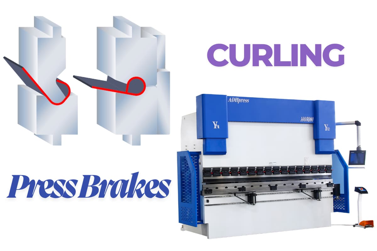
Knowing how to create a curl on a press brake with precision and consistency is a critical skill that separates basic operators from true fabrication experts. While a simple bend is straightforward, a curl is a complex, engineered feature that adds strength, safety, and value to any part.
This guide moves beyond fundamentals to deliver a complete methodology for mastering the curl. From engineering principles and tooling selection to step-by-step execution and advanced troubleshooting, we provide the definitive framework for achieving a perfect curl, every time.
I. Core Understanding: Redefining Press Brake Curling (The Anatomy of a Curl)
Curling on a press brake is far more than simply bending the edge of a sheet. It is a finely tuned interaction between mechanical principles and material science at a micro level. If you treat it as a purely decorative operation, you have already lost the game.
Curling is a high-end forming process that converts a 2D flat sheet into a 3D, structurally rigid feature. At its core, it uses precisely controlled pressure to force the metal to undergo continuous plastic flow within a very narrow zone, ultimately forming a closed or semi-closed hollow profile.
1.1 The Essence and Industrial Definition of Curling
In rigorous industrial terms, curling is fundamentally different from the more common hemming operation. Hemming folds the material back onto itself to create a flat, double-layered edge. Curling, by contrast, forms a hollow, circular cross-section. This hollow geometry is the source of its distinctive mechanical performance.
From a process standpoint, curling is rarely a single-step operation; it is typically a progressive multi-stage forming system. It demands that the operator thoroughly understands how metal flows under load:
- Stage 1 (Pre-bending): Break the original plane-stress state and establish an initial guiding radius.
- Stage 2 (Curling/Closing): Guide the sheet edge to roll inward along a defined path, using the die cavity to force the material to overcome internal tension and close into a circular ring.
Depending on the final shape and its position relative to the original sheet plane, curling is clearly divided into on-center curls and off-center curls. In an on-center curl, the curl’s center lies on the extension of the sheet’s neutral axis and is often used in hinge-type structures. In an off-center curl, the center is offset from the sheet plane and is commonly used as an edge closure. Understanding this geometric distinction is essential for selecting the right tooling and for accurately calculating the flat pattern.
1.2 The Three Core Value Dimensions of Curling
Why add a curling operation to an already complex manufacturing sequence? Experienced engineers know that a well-executed curl delivers three key dimensions of added value:
- Geometric Leap in Structural Performance (Structural Reinforcement) This is the most “hardcore” benefit of curling. From a mechanics perspective, the edge of a sheet is inherently weak and prone to buckling. By changing the cross-sectional shape, curling dramatically increases the moment of inertia at the edge. It is as if you have integrated a seamless tube along the perimeter of a thin sheet: the edge can now resist much higher bending loads and effectively suppress “oil canning” in large flat panels, significantly boosting overall stiffness without increasing material thickness.
- Safety Logic and Ergonomics (Safety & Ergonomics) In metal fabrication, sharp edges left by laser cutting or punching are latent safety hazards. Grinding can deburr them, but it is slow and hard to keep consistent. Curling permanently tucks the sharp cut edge inside a smooth radius, creating a truly safe “touch zone.” This not only supports compliance with ISO safety standards and greatly reduces injury risk for assembly workers and end users, it also reflects the human-centered mindset that defines premium manufacturing.
- Process Robustness and Surface Aesthetics (Aesthetics & Process Stability) Beyond the clean, high-end appearance, curling solves a major pain point in finishing operations: edge coverage. On sharp corners, liquid and powder coatings tend to pull back due to surface tension, thinning the film and making those areas prone to corrosion. A rounded curl gives coatings an ideal surface to cling to, substantially extending corrosion resistance. In addition, the hollow channel formed by the curl is often intentionally used as a conduit for wiring or as a bore for hinge pins, achieving an elegant fusion of structure and function.
1.3 The “Gold Standard” for Curl Quality
What qualifies as a “world-class” curl? By our standards, it should stand up to microscopic scrutiny and meet strict criteria in three areas:
- Quantified Geometric Accuracy An average curl may look roughly round to the naked eye; an excellent curl maintains a consistent radius across its entire length. Industry leaders typically hold straightness along the curl to within 0.1 mm per meter, and roundness (closure) to within 5% of the radius. Any “teardrop” shape or flattened end section is clear evidence of incorrect process settings.
- Respect for Material Grain (Grain Direction Mastery) This is where novices and experts part ways. Sheet metal is anisotropic; the grain structure formed during rolling largely determines the forming outcome. The gold standard is to keep the bend line as close to perpendicular to the rolling direction as possible. If production constraints force you to curl parallel to the grain (a common consequence of nesting optimization), you must use a larger radius or apply special annealing treatments. Otherwise, the outer surface of the curl is highly susceptible to micro-cracking and visually unacceptable “orange peel” texture.
- Perfect Closure and Springback Control A top-tier curl should close tightly without crushed flats or excessive pinch marks. Achieving this demands precise springback compensation. Unlike a simple 90° bend, springback in curling is governed by complex curvature changes. Underestimating springback leaves the curl partially open; overcompensation imprints the tool profile onto the workpiece. True perfection is when, at the instant the tooling separates, the elastic recovery places the metal exactly at the intended design geometry—no more, no less.
II. Engineering Logic: Mathematical Models and Physical Mechanisms (The Engineering Behind)
If operator “feel” defines the lower limit of curling quality, then understanding the engineering logic defines the upper limit. In the split second when the press brake ram descends, the sheet metal is not simply displaced in space; it undergoes a complex physical evolution involving elasto-plastic mechanics, friction, and changes in microstructure. To move beyond rule-of-thumb practice, we need to re-examine this process through mathematical models and physical mechanisms.
2.1 Physical Mechanisms of Curl Formation
Fundamentally, curling is a continuous plastic flow process with changing curvature. Unlike a conventional V-bend, curling demands that the material transition from a flat plane to a helical surface over a very short stroke, undergoing severe topological transformation in the process.
- Dynamic Shift of the Neutral Axis Under bending moment, the outer fibers of the sheet are in tension and the inner fibers are in compression. Between them lies a transition surface where the stress is essentially zero: the neutral axis. For conventional bends with a relatively large radius, the neutral axis sits near the mid‑thickness (0.5T). In tight curls with a very small radius (typically R < 2T), the neutral axis shifts significantly toward the compression side (the inside) to maintain moment equilibrium across the section. This physical migration is what makes flat‑pattern calculation so tricky. If you do not correct the K‑factor to reflect this shift, your developed length will be wrong: the curl will be “too short” and fail to close, or “too long” and jam the tool.
- Radial & Tangential Springback Springback is the nemesis of all metal forming, and in curling it becomes particularly critical. Curl springback appears in two coupled modes:
- Radial springback: increases the final curl radius so the curl does not grip tightly.
- Tangential springback: causes the open end of the curl to flare apart, preventing a perfectly closed circle.
From a physical standpoint, both arise from the release of elastic strain energy stored in the material. A robust curling process effectively uses the tool geometry to over‑bend the material, deliberately reserving “room” for springback so that, after unloading, the part relaxes exactly to the intended final dimensions.
2.2 Key Process Parameter Calculations
Before any metal touches the tooling, accurate calculation is the only real way to avoid costly trial‑and‑error. The following two models form the core analytical framework for curl design.
Flat Length & Curl Allowance Never rely on the default bend coefficients in your CAD system for curling. Curl flat length must be calculated from a geometry model tailored to the curl profile. A commonly used empirical expression is:
Forming Tonnage Estimation Curling is typically split into two stages: pre‑bend and final form. The pre‑bend stage can generally use the standard air‑bending tonnage formula:
where P is in kN, S is sheet thickness in mm, L is bend length in m, and V is the lower-die opening.
During final forming, however, the material is forced into full closure and calibration, so the actual tonnage required is often 2–3× that of standard bending. The press brake operator must ensure adequate tonnage capacity and safety margin; otherwise the ram may stall or the hydraulic system may be overloaded.
2.3 Material Science Constraints on Curling
Not every metal is a good candidate for curling. The microstructural properties of the material impose hard physical limits on the process. Ignoring these limits is a direct path to scrap.
- Ductility & Fracture Limit Curling is essentially a stress test of a material’s ductility. The key indicator is the minimum bend radius the material can tolerate without failure.
- Aluminum alloys (e.g., 5052-H32): typically support inside curl radii of 0.5T or even smaller, offering excellent formability.
- Stainless steel (e.g., 304): prone to severe work hardening. A practical inside radius is usually no less than 1.0T–1.5T; otherwise the outer surface will exhibit pronounced orange peel and may develop micro‑cracks.
- High‑carbon steel: very difficult to curl. Annealing or hot forming is typically required.
- Grain Direction Anisotropy This is a hidden risk that beginners often overlook. During rolling, sheet metal develops an elongated, fiber‑like grain structure.
- Best practice: orient the bend line perpendicular to the rolling direction (cross‑grain). In this orientation the material can withstand the highest tensile strain, resulting in a smooth, uniform outer curl.
- High‑risk option: bend line parallel to the rolling direction (with‑grain). Here the material tends to separate along grain boundaries, causing cracking on the outer side of the curl. If this orientation is unavoidable during nesting, you must significantly increase the curl radius to reduce the strain level.
- Work‑Hardening Exponent (n‑Value) Curling is a continuous deformation process in which the material keeps hardening as it forms. The high n‑value of stainless steels means the force required ramps up sharply during the closing phase of the curl, and the resulting springback is substantial. Tooling must therefore be designed with greater springback compensation, and the machine settings should include a longer dwell time at the bottom of the stroke to help relieve internal stresses.
III. Preparation & Setup: Tooling, Equipment, and Materials
The few minutes of preparation before the press brake ram starts its downstroke will determine whether the next several hours of production run smoothly or devolve into chaos. For a high‑precision process like curling, relying on the operator’s “feel” to compensate for poor system setup is extremely risky. Every flawless curled part is backed by a rigorous, quantified, and validated preparation procedure.
3.1 Curl Tooling Selection Strategy
Choosing curling tools is far more than picking a V‑die that matches the sheet thickness. It is a strategic trade‑off between efficiency, accuracy, and cost. In curling applications, generic standard tools usually only deliver “good enough” results; professional‑grade production calls for a precisely matched system solution.
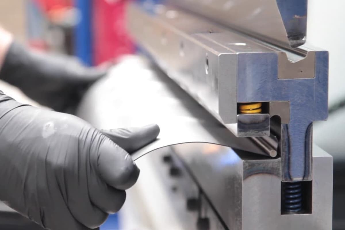
Dedicated Multi‑Stage Curling Systems For parts that demand exceptional roundness and tight closure, dedicated curling dies are the tool of choice. These are typically designed as two‑stage or composite forming systems:
- First station (pre‑form groove): forms a precise "J"‑shape or large‑radius profile at the sheet edge to establish the initial curl lead‑in.
- Second station (curling groove): uses a semi‑cylindrical cavity to guide the material to roll back tangentially and close into a full curl.
Non‑negotiable selection rule: Always prioritize hardened dies that have been precision ground. For high-strength materials such as stainless steel, upgrade die materials to Cr12MoV (D2) or high-speed steel (HSS) with a hardness of at least HRC 58–62. Follow a strict “hard against hard” principle to prevent rapid wear or deformation of the die under high-pressure friction.
Rotary bending’s game‑changing edge (The Rotary Bending Advantage) For products with ultra‑strict surface quality requirements—such as medical devices or premium appliance panels—rotary bending dies are a frequently overlooked “secret weapon.”
- Principle: A rotating, saddle‑shaped cam is used in place of a fixed V‑shaped lower die.
- Advantages: During forming, the die rotates in sync with the material, eliminating sliding friction and thus preventing scratches at the source. Just as important, it effectively suppresses the sheet’s “whip” at the end, greatly improving operator safety and enabling reliable pre‑bending even with very short flange lengths.
Surface hardening and coating technology Don’t skimp on the die surface. For high‑volume production, apply TiN (titanium nitride) or TiCN (titanium carbonitride) coatings to the curling grooves. Though only a few microns thick, these coatings can boost surface hardness to above HV 2500, and their extremely low friction coefficient acts as a permanent solid lubricant, drastically reducing the risk of the material seizing and welding to the die.
3.2 Equipment calibration and precision control checklist
The curling process has virtually zero tolerance for accumulated error. A 0.1 mm backgauge deviation can easily turn into a visible open seam or flattened section in the final curl. Before starting the machine, you must follow the calibration procedure with surgical precision:
- Micron-level backgauge calibration The flange length is the lifeline of a successful curl.
- Parallelism check: Use a dial indicator along the beam to verify that the backgauge fingers are parallel to the lower die centerline within 0.05 mm/m. Any skew will cause one end of the curl to be tight and the other loose.
- Z-axis positioning accuracy: Check the finger height. For pre‑bending before curling, the fingers must support the sheet exactly at mid‑thickness. If they’re too high, the sheet can slip underneath; too low, and the sheet may lift, leading to unstable dimensions.
- Ram repeatability and dwell‑under‑pressure test The final closure of the curl typically depends on precise control of the ram’s bottom dead center (BDC).
- Accuracy verification: Ensure the hydraulic system’s repeat positioning accuracy is within ±0.01 mm. For older machines, run unloaded for 15 minutes to warm up, then recalibrate.
- Dwell test: Curling requires a relatively long dwell time to release internal stresses in the material. Check for internal leakage in the cylinders under high pressure and confirm that pressure remains constant throughout the dwell; otherwise, springback will become unpredictable.
- Dynamic crowning compensation “Bulged in the middle, lifted at the ends” is the nightmare scenario for long‑part curling. Once the curl length exceeds about 60% of the machine bed length, deflection of the frame and ram becomes unavoidable.
- Active compensation: Whether using CNC hydraulic crowning or mechanical wedge systems, you must preset the compensation according to total tonnage.
- Trial‑and‑error verification: Before production, run a full‑length test bend on scrap. If the center of the curl remains open while the ends are already fully closed, increase crowning; if the opposite occurs, reduce it.
3.3 Material preparation and surface protection
Even with top‑tier tooling and perfectly calibrated equipment, poor incoming material can still ruin everything. As the first link in the process chain, material preparation is your primary line of quality defense.
- Deburring the edges: more than just safety In curling, edge condition is a matter of forming physics. Tiny burrs left by laser cutting or shearing become high‑risk stress concentration points.
- Mandatory rule: Before curling, thoroughly deburr or chamfer all sheet edges. During rolling, untreated burrs are subjected to intense stretching and can easily tear, propagating into visible cracks. In addition, hardened burrs act like miniature cutting tools, quickly scratching the expensive curling die cavities.
- Cleanliness and lubricant control
- Remove contaminants: Oxide scale from laser cutting and metal dust from the shop floor, once trapped between the die and the sheet under high pressure, will leave permanent pitting on an otherwise perfect curl. Always wipe all contact areas with industrial cleaning cloths.
- Lubrication strategy: For aluminum alloys and stainless steel, apply a small amount of extreme‑pressure forming oil or forming wax in the curling zone. This not only reduces the required tonnage but also prevents cold welding (galling) between the material and the die, ensuring a mirror‑smooth curled surface.
- The art of using protective films For mirror‑finish stainless steel or pre‑coated sheet, PE protective film is standard. However, during curling you must pay attention to the following:
- Thickness compensation: Protective films are typically 0.05–0.1 mm thick. This thickness must be included in precise flat‑pattern calculations and in setting tool clearances.
- Film toughness: Use “laser film” or high‑toughness films designed for deep drawing to prevent the film from tearing during curling and getting wedged deep in the die cavity, which can be extremely difficult to clean out.
IV. Practical Guide: Three Complete Curling Workflows (Step‑by‑Step Execution)
Once the theoretical model is in place and the equipment is fully calibrated, it’s time for execution. Curling success is decided in fractions of a millimeter, and different applications call for three distinct process routes. This chapter strips away excess theory and, through a set of surgical‑precision steps, walks through the practical details of three core curling solutions.
4.1 Method 1: Standard two‑step process (dedicated tooling / high precision)
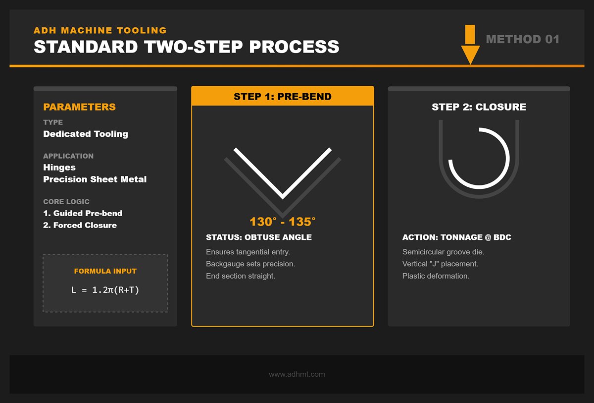
Best suited for: High‑volume production, hinge manufacturing, and precision sheet metal parts with extremely tight requirements on roundness and closure. Core idea: Use dedicated curling dies to decompose the complex helical motion into two linear actions: “guided pre‑bend” followed by “forced closure.”
Step 1: The golden pre‑bend
This is the step most operators underestimate—and the most critical one. Pre‑bending is not just about folding the sheet; it is about defining the material’s “flow vector.”
- Angle setting: Typically set a 130°–135° obtuse angle (i.e., an internal angle of 45°–50°). This specific range ensures that in the second step the sheet edge enters the curling die cavity along an ideal tangential path instead of striking the die wall perpendicularly.
- Backgauge positioning: Backgauge location must be exceptionally accurate. The pre‑bend flange length directly defines the final curl circumference.
- Calculation formula: L_pre ≈ 1.2 × π × (R + T). If the flange is too short, the edge cannot fully close; if it is too long, it will interfere inside the curl and distort the outer diameter.
- Inspection point: The end of the pre-bent section must remain straight, with no visible indentations. Any marks here will turn into noticeable visual defects after curling.
Step 2: Cavity Closing
- Tool change/station shift: Switch to an upper or lower die with a semicircular groove for curling.
- Engagement and curling: Place the pre-bent "J"-shaped workpiece vertically into the curling die. As the ram descends, the pre-bend angle guides the edge so it contacts the bottom of the cavity and starts to slide along the curved surface, rolling into shape.
- Over-bend control: When the ram reaches bottom dead center (BDC), apply enough tonnage to force the material into plastic deformation. At this point, the material is essentially being "upset" inside the cavity.
🔴 Master’s Note: If the finished curl looks like a teardrop instead of a true circle, the first-step pre-bend angle is usually too large (for example, more than 150°). The edge contacts the opposite wall of the die too early and loses its swing space. Reduce the pre-bend angle to give the material more "runway."
4.2 Method 2: Multi-step Approximation (No Dedicated Dies / Large Radius)
Best for: Prototype builds, small-batch production, extra-large radius curls (such as handrails), or emergency work when no dedicated curling die is available. Core idea: Apply the principles of calculus—use many small bends (bumping / step bending) to approximate an arc. This method trades time and cycle count for tooling cost.
Step 1: Mathematical Breakdown and Programming
Do not work by feel. You must program exact step parameters into the CNC system.
- Pitch calculation: Keep the pitch between 2 mm and 5 mm. A smaller pitch gives a smoother arc but increases the risk of cumulative error.
- Angle segmentation: For example, if you need a 270° large-radius curl and you divide it into 30 hits, each hit will bend about 9°.
- Springback compensation: Since this is air bending, you must factor in springback for every hit. The programmed angle for each bend should be 1°–2° less than the theoretical value.
Step 2: Executing the Incremental Bends
- Feed direction: Strongly recommended to work from the outside in—start at the very edge of the sheet and then step inward. This lets the operator always grip a flat section of the sheet, improving control and positioning accuracy.
- Macro calibration: After every 5–10 hits, check the radius with a radius gauge. Errors accumulate: a 0.1° deviation on the first bend can result in severe distortion by the 30th bend.
🔴 Master’s Note: The biggest enemy of this method is the "polygon effect"—visible facets instead of a smooth curve. To smooth out those flats, you can use a urethane pad as the lower die, or run the part through a roll-forming / roll-straightening machine after bending for final correction.
4.3 Method 3: Mandrel-Assisted Curling (Special Requirements / High Strength)
Best for: High-strength hinges, handles, edge structures that must carry heavy loads, or materials with very poor ductility (prone to cracking) where a mandrel is needed to distribute stress. Core idea: Embed a rigid mandrel (such as steel wire or a stainless rod) inside the curl and use it as an internal die to strictly control the deformation path of the material.
Step 1: Forming the U-shaped Channel
Unlike the standard method, this approach starts by forming a sufficiently spacious "U" or "C" channel. The opening width must be slightly larger than the mandrel diameter (typically by 0.5 mm–1 mm) so the mandrel can be inserted smoothly.
Step 2: Mandrel Insertion and Positioning
- Lubrication: Before inserting the mandrel, be sure to coat its surface with extreme-pressure grease (such as molybdenum disulfide). This is critical to prevent the mandrel from seizing inside the curl.
- Positioning: Make sure the mandrel is fully seated at the bottom of the channel, and leave enough length exposed at both ends so it can be removed later if required.
Step 2.5: Offset Closing
This is the most technique-sensitive step.
- Asymmetric loading: When closing with a flat die, the center of pressure should not be aligned with the center of the mandrel; it should be offset slightly toward the open side of the channel.
- Wrap forming: Force the sheet edge to tightly wrap around the mandrel. If the mandrel will remain as a structural element, increase tonnage for a coining operation to eliminate any gaps so the metal and mandrel act as a single, highly rigid composite.
🔴 Master’s Note: In mandrel-assisted curling, the most dangerous failure mode is "lock-up." For processes using a removable mandrel, never fully coin the last step; you must leave room for springback. A common practice is to use a mandrel about 0.2 mm smaller than the target inner diameter. After the mandrel is removed, elastic springback brings the curl to the exact design ID.
V. Troubleshooting & Optimization: Eliminating Common Defects
Tuning a curling process is essentially a battle against micrometer-level errors. Whether the part coming off the press brake is a perfect circular profile or a piece of scrap often depends on whether the operator can see through the symptoms to the underlying physics.
Instead of blind trial and error, build a systematic diagnostic workflow. This chapter breaks down the three most critical defect types in curling and provides definitive corrective strategies.
5.1 Geometric Shape Defects
These are the most obvious—and the most frustrating—issues: it may look like a curl, but it’s not round, and in some cases it won’t even close.
Defect 1: Teardrop Shape
- Symptoms: The curl is no longer a true circle but looks like a droplet or pear shape with a pointed end, often accompanied by the tail of the curl being forced too far inward and causing internal interference.
- Root cause analysis: This is the classic "over-pre-bend" syndrome. If the pre-bend angle in Step 1 is set too sharp (for example, using a standard 90° instead of the recommended 135°), the edge of the material hits the inner wall of the curling die too early. With insufficient swing space, the material is squeezed inward instead of sliding tangentially along the die radius.
- Corrective action:
- Increase the pre-bend angle: Adjust the pre-bend inner angle to 130° - 140°. This gives the material enough "runway" to enter the curved lead-in surface of the curling die smoothly and tangentially.
- Reduce the pre-bend radius: If the pre-bend angle is correct but you still get a teardrop shape, check the punch tip radius. An oversized pre-bend radius disperses the guiding force; switch to a sharper punch (e.g., R = 0.5 mm - 1 mm) to re-establish a precise bend line.
Defect 2: Curl Not Fully Closed (Open Curl / Springback)
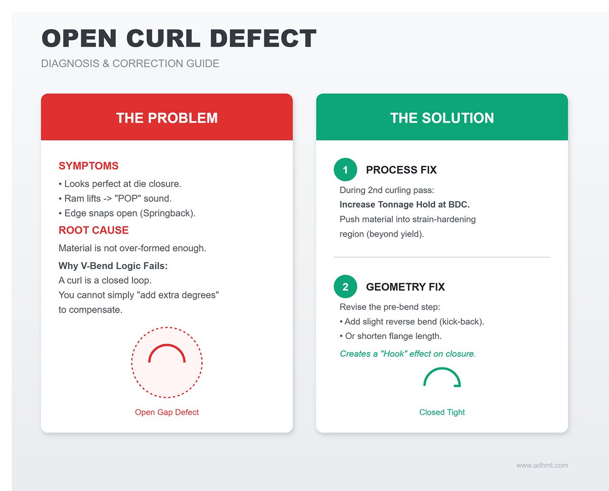
- Symptoms: The curl looks perfect at full die closure, but the moment the ram lifts, the edge snaps open with a “pop,” leaving an unacceptable gap.
- Root cause analysis: It’s not just material springback; more often, the curl simply hasn’t been over-formed enough. A curl is a closed loop, so standard springback-compensation logic for V-bending breaks down here—you can’t just “add a few extra degrees” the way you would with an open bend.
- Fix strategy:
- Correcting under-bending: During the second curling pass, slightly increase the tonnage hold at bottom dead center to push the material into the strain-hardening region beyond yield.
- Geometric trickery: If springback remains severe (e.g., with high-strength stainless steel), revise the pre-bend step. Add a very slight reverse bend (kick-back) at the end of the pre-bend, or shorten the flange length a bit so that, upon closure, the curled edge “hooks” more deeply into the inside surface.
5.2 Global Distortion Defects
When working with long parts (such as doors or covers over 1 meter), local curls may look perfect, yet the overall part ends up distorted.
Defect 1: Banana-Shaped Bending (Canoeing / Bowing)
- Symptoms: Along the length, the part bows—either the middle bulges up or both ends lift—resembling a canoe.
- Root cause analysis: Curling is, in essence, an extreme combination of tension and compression along the sheet edge. This intense plastic deformation at one edge introduces substantial residual stress on that side, while the opposite, unworked side remains largely stress-free. The resulting stress imbalance generates a bending moment that drives the part to curve along its long axis.
- Fix strategy:
- Reverse use of crowning compensation: Conventional crowning is used to keep bend angles uniform. In curling, however, you may deliberately tune the crowning value—or even add shims under the die—to counteract stress-induced distortion.
- Segmented forming strategy: For very long parts, don’t try to complete the curl in one continuous pass. Use a segmented feed approach—“center outwards” or “ends toward the center”—to break up the continuous buildup of residual stresses.
Defect 2: Helical Twist (Twisting)
- Symptoms: The cross-sections at the two ends of the part are no longer in the same plane; the part looks like it has been twisted like a licorice stick.
- Root cause analysis: Typically caused by parallelism errors in the equipment or non-uniform material grain behavior. If the backgauge is not parallel left-to-right, or if the rolling grain runs at an angle across the blank, the feed resistance during curling will differ from side to side, inducing twist.
- Fix strategy:
- Parallelism calibration: Recalibrate the backgauge fingers to be parallel to the die centerline, keeping error within 0.05 mm.
- Grain alignment: Check nesting orientation during blanking and ensure a consistent geometric relationship between the bend line and rolling direction (strictly perpendicular or strictly parallel). Never curl parts with the grain running at an angle to the bend line.
5.3 Surface and Structural Defects
In high-end manufacturing, parts that function correctly but look flawed are still considered scrap.
Defect 1: Galling & Pickup
- Symptoms: The outer surface of the curl shows obvious scratches, rough streaks, or even metal debris adhered inside the die cavity.
- Root cause analysis: This is essentially a “cold welding” phenomenon in metal forming. Under extreme contact pressure, aluminum alloys and stainless steels can smear and weld microscopically to the tool steel surface. As the stroke count climbs, these welded spots turn into extremely sharp cutting edges.
- Fix strategy:
- Lubrication barrier: For aluminum parts, emulsified oil or forming wax is mandatory; for stainless steel, use a high-EP (extreme pressure) forming lubricant.
- Physical barrier: Place a $0.1\text{ mm}$ urethane film between the die and sheet, or use tools with a PTFE (Teflon) coating. This not only virtually eliminates galling but also protects expensive mirror-finish materials.
Defect 2: Orange Peel & Micro-cracking

- Symptoms: The outer (tension) side of the curl surface turns rough with an orange-peel texture; in severe cases, fine surface cracks appear.
- Root cause analysis: This signals coarse grains or exhausted ductility. When the bend radius is too small relative to thickness (R < T), or the bend line runs parallel to the rolling direction, grain boundaries are forced apart and begin to tear.
- Fix strategy:
- Grain management: This is the golden rule—whenever possible, orient the curl axis perpendicular to the rolling direction (cross-grain).
- Annealing: For hard materials that must be curled at a small radius, localized induction annealing can restore ductility.
- Increase the radius: If design permits, increasing the curl radius is the most economical way to eliminate orange peel. Physics always wins—don’t force brittle material to perform gymnastics.
VI. Safety Barriers and Preventive Maintenance (Safety & Maintenance)
Within sheet metal fabrication, curling is regarded as one of the highest-risk operations because it involves high-force closure, intense material flow, and nonlinear springback. Safety is not just a checklist on the wall; it is respect for and control of physical energy.
Maintenance is not just wiping off grease; it is preserving the value of a precision manufacturing system. This chapter goes beyond generic shop rules to focus on the unique critical hazards of curling and the strategies for long-term, reliable operation.
6.1 Special Safety Red Lines for Curling Operations
The biggest difference between curling and conventional bending lies in the material’s dynamic behavior and the fully enclosed nature of the tooling. Ignoring any of the following three “red lines” is a common root cause of severe injuries or catastrophic equipment damage.
Red Line 1: The Razor-Edge Effect of the Pre-bent Flange In most curling accidents, the injury doesn’t occur at the moment of machine downstroke but during part handling. After the first pre-bend step, the sheet edge becomes an extremely sharp $30^{\circ} - 45^{\circ}$ angle, with microscopic serrations from work hardening.
- Upgraded PPE: Standard cotton work gloves offer virtually no protection here. Operators must wear high-cut-resistance gloves rated at ANSI A4 / EN 388 Level E or better.
- Operating rule: When feeding a pre-bent part into the curling die, never press on the flange tip with bare hands for positioning. Use auxiliary magnetic handles, or apply the “side-grip” method—hold the non-curled side areas of the sheet—and always assume that edge is an exposed scalpel.
Red Line 2: The “counter‑intuitive” pinch point in the curl‑closure zone In conventional V‑bending, the primary danger zone is directly under the punch. During curling, however, the material travels back in along a circular path.
- Hidden trap: As the curl closes, the trailing end of the part will sweep rapidly across the area in front of the tooling. If the operator habitually rests fingers on the sheet edge to help with feeding, they can be caught by the returning metal edge like an animal trap snapping shut.
- Defense strategy: Enforce a “two‑hand control” principle, or correctly configure the light curtain’s blanking function. For small parts, mandate the use of safety pliers or a feed slide device so that fingers never cross the front line of the lower die.
Red Line 3: Tonnage overload and die rupture Curling—especially tight coining of the curl—is highly prone to tonnage overload. Unlike air bending, the curl‑closure phase is rigid stamping. A ram depth error of just 0.1 mm can multiply the applied force.
- Energy control: Never “test press” without first calculating the required tonnage. Hardened tool steel will not yield plastically under overload; instead, it can shatter like glass in a catastrophic failure, sending high‑velocity metal fragments with potentially lethal energy.
- Visual last line of defense: When running this operation, polycarbonate side guards and high‑impact safety goggles are your final protection and must never be removed.
6.2 Long‑term maintenance of tooling and equipment
A precision curling die is expensive, and its service life depends directly on how well you manage friction and stress. Maintenance is not about fixing breakdowns after they occur; it is about preventing loss of accuracy.
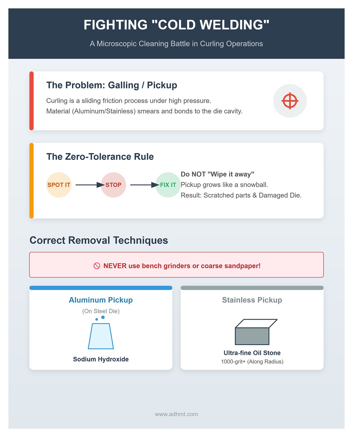
Fighting “cold welding”: a microscopic cleaning battle Curling is a sliding friction process under high pressure and is very prone to galling/pickup—where workpiece material (especially aluminum and stainless steel) smears and bonds onto the die cavity.
- Zero‑tolerance rule: The moment you spot even a tiny metal pickup in the die cavity, stop the machine and fix it. Do not try to “wipe it away” with the next stroke. That will only let the pickup grow like a snowball, eventually scratching every subsequent part and permanently damaging the die surface.
- Removal techniques: Never use a bench grinder or coarse sandpaper on the die cavity. For aluminum pickup on a steel die, use a sodium hydroxide solution to chemically remove it. For stainless steel pickup, use an ultra‑fine oil stone (1000‑grit or higher) to hand‑polish along the cavity radius.
Preventing the “saddle effect”: load‑balancing strategy Operators tend to work at the center of the press brake. Over time this can create slight permanent deformation in the center of the bed and ram—the so‑called saddle effect. For curl forming, which demands extremely high straightness, this is fatal.
- Dynamic rotation: Establish a standard operating procedure (SOP) that requires operators to alternate between different stations on the die (left, center, right).
- Segmented management: For long dies, mark them in segments. When processing short parts, use the less‑worn end sections first to even out wear along the full die length.
The art of lubrication: building a friction barrier Lubrication for curling dies is not just about rust prevention; it is an integral part of the process.
- Dry lubrication: To avoid oil contamination of parts, periodically spray the die cavity with a molybdenum disulfide (MoS₂) dry‑film lubricant. It forms a micron‑thick, high‑pressure protective layer on the die surface, significantly reducing the coefficient of friction and extending die life by more than 30%.
🔴 Master‑level maintenance checklist (The Master Checklist): Every time a die is removed and stored, you must complete these three steps:
- Clean: Thoroughly remove all metal dust and sludge.
- Inspect: Under magnification, check the lip of the curling cavity for any chipping.
- Rust‑proof: Apply long‑term rust inhibitor and store the die suspended in a dedicated wooden crate. Never stack working surfaces directly against each other.
Only by embedding safety awareness into muscle memory and turning maintenance standards into enforceable rules can you ensure that, even after tens of thousands of cycles, the curling process still delivers the same flawless quality as the very first part.
VII. Conclusion
Mastering the curl on a brake press requires moving beyond basic bending into a realm of engineered precision. By understanding the core value of a curl, applying the correct engineering principles, and executing with a systematic approach, you can transform a simple sheet of metal into a safe, strong, and highly functional component when using a modern press brake. This guide has provided the end-to-end framework to achieve that result consistently.
Ready to apply this expertise? Whether you need guidance on tooling, process optimization, or are considering new equipment, the specialists at ADH Machine Tool are here to help.
Contact us at ADH today to explore our press brake solutions and let us help you achieve superior results in all your forming operations.


