How to cut up a press brake die is a precision-driven process that defines tooling flexibility and downstream efficiency in sheet metal fabrication. Before shaping or segmenting a die, it’s critical to evaluate the actual value, understand the material and heat treatment status, design for modularity and clearance, and choose a process route that safeguards both accuracy and longevity.
This guide distills the essential stages—from strategic decision-making and segmentation to execution and precision verification—to ensure every cut supports performance, safety, and future adaptability.
I. Strategic Decision Module: The Assessment You Must Complete Before You Start Cutting
On the shop floor, a high‑quality press brake die is a significant investment. Cutting a die is not just a physical separation—it is an irreversible restructuring of a valuable asset. Before you fire up a grinder or wire EDM, any seasoned machine operator or shop supervisor must carry out a rigorous strategic assessment. Acting rashly can turn an expensive die into scrap and may also introduce long‑term accuracy issues that are hard to detect but costly to fix.
1.1 Defining Core Value and Use Scenarios
Before you decide to cut a die, you need to be clear about the real driving force behind this “operation.” In general, cutting only makes sense when the long‑term productivity gains clearly outweigh the loss in asset value. Evaluate the payoff against one of the three main scenarios below:
- Scenario A: Sectionalizing – The Efficiency Multiplier
This is where die cutting delivers the highest value. By cutting a full‑length die (for example 3 m or 10 ft) into standardized short sections (such as 10 mm, 15 mm, 20 mm, 40 mm, 50 mm, 100 mm, 200 mm, etc.), you dramatically increase your flexibility when changing setups.- Decision criterion: If your shop frequently runs parts in varying widths, or often needs to build up specific lengths for box bending, sectionalizing can cut setup time by more than 50%. In this case, cutting is not just acceptable—it becomes the rational, even necessary, choice.
- Scenario B: Clearance Cuts – Solving Interference Problems
When bending deep box sections or parts with return flanges, standard tooling often clashes with the workpiece.- Decision criterion: By cutting special windows or removing the “horns” of the die, you can eliminate mechanical interference. However, such cuts make the tool highly specialized; once modified, it may no longer be suitable for general full‑length bending. You must confirm that the profit from the specific job more than covers the cost of dedicating that die to special use.
- Scenario C: Damage Repair and Salvage
This applies when a portion of a long die—typically near the center—has been overloaded and shows dents, chipping, or cracking.- Decision criterion: If the damage is localized, cutting out the defective section and reworking the remaining segments into two shorter, fully usable dies is an excellent way to stop the financial bleeding. This approach is far more economical than scrapping the entire die.
1.2 “Health Check” of Material Hardness and Heat Treatment
This step is crucial for defining your technical approach. Press brake dies are nothing like mild steel bars: they are typically made from 4140 (42CrMo) or higher‑grade tool steels and go through precise heat treatment. If you ignore hardness and go straight to the saw, at best you will destroy the blade; at worst you will overheat and soften the die surface, effectively ruining it.
Before cutting, you need to understand the die’s “physical condition”:
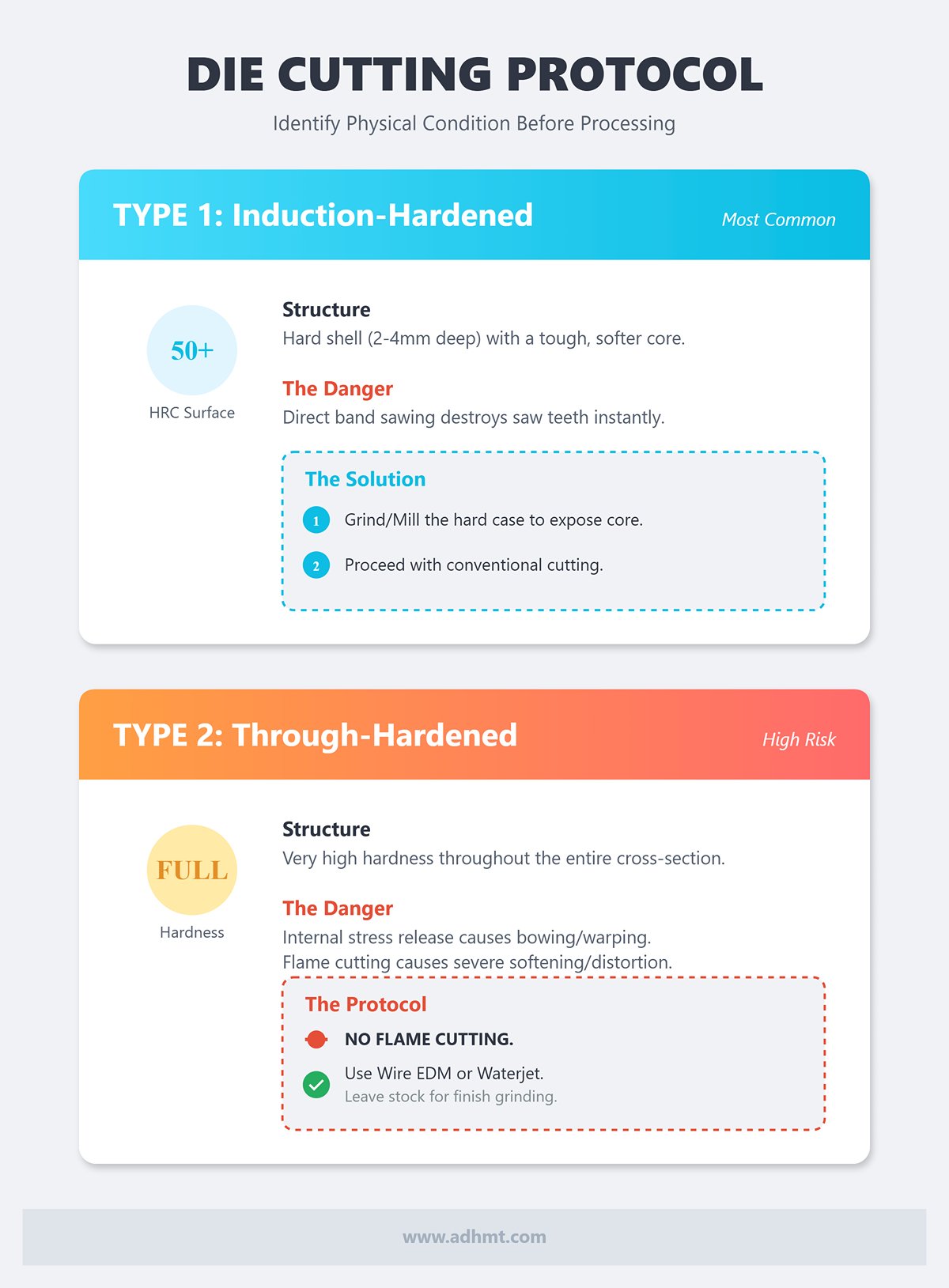
- Type 1: Induction‑Hardened Dies – Hard Shell, Tough Core
This is the most common configuration for modern precision dies. The working surfaces (V opening and punch tip) are induction hardened to HRC 50–60, typically to a depth of 2–4 mm, while the core remains in a tempered state around HRC 28–32 to maintain toughness.- Cutting risk: If you use a band saw directly, the teeth will be dulled almost instantly when they hit the hardened surface layer.
- Recommended approach: First grind through the hardened case with an angle grinder or carbide end mill to expose the softer core, then proceed with conventional cutting methods. Alternatively, go straight to wire EDM or abrasive wheel cutting.
- Type 2: Through‑Hardened Dies – Hard All the Way Through
Older dies and certain high‑strength specialty tools may be fully hardened, with very high hardness throughout the cross‑section.- Cutting risk: These dies contain significant internal residual stresses. Once you cut them, the stress balance is broken and they tend to bow or warp. The two new sections may no longer be straight, which leads to inconsistent bend angles along the length.
- Recommended approach: Never use flame cutting on this type of die; it will cause severe softening and distortion. Use wire EDM or waterjet cutting, and allow sufficient stock for finish grinding so you can correct any warpage.
💡 A Master’s Trick from 20 Years on the Floor – The File Test
If you don’t have access to an expensive hardness tester, use a new, standard file. Hold it at roughly a 30° angle and push it lightly across a non‑working surface of the die.
• If the file skates and only leaves a faint mark, hardness is very high (> 55 HRC); you’ll need grinding or EDM to cut it.
• If the file bites into the metal, hardness is moderate and you may be able to use a carbide‑tipped cold saw or a high‑quality bimetal band saw.
II. Design Module: Building a “Lego‑Style” High‑Efficiency Tooling System
Your brain has to go to work before your hands do. A common mistake is to grab a long die and cut it randomly just to get one urgent job out the door, only to find that this expensive tool has become nearly useless for future production.
True, expert‑level die cutting is not just doing “subtraction.” It is about using smart design to create “multiplication.” With a well‑thought‑out segmentation plan, you can transform a single, heavy, full‑length die into a flexible, modular Lego‑style system. This not only solves today’s interference or setup problem, it also prepares your tooling inventory to handle 90% of your future non‑standard bending jobs.
2.1 The Golden Segmentation Strategy
If your goal is to segment a standard‑length die (such as 835 mm or 415 mm), never just cut it into a few equal sections. Instead, follow the industry‑proven “golden segmentation” approach. This method is based on binary and combinatorial principles and aims to cover the widest possible range of bending lengths with the fewest individual segments.
Recommended standard cut pattern (example for an 835 mm die):
A well‑designed segment set should include independent modules in the following lengths:
- 10 mm, 15 mm, 20 mm, 40 mm, 50 mm (fine adjustment segments)
- 100 mm (typically two pieces, used as “end blocks” on the left and right)
- 200 mm, 300 mm (main filler segments)
The “magic” of this combination lies in the fact that:
- 5 mm increment coverage: By mixing and matching these modules, you can build any length from 10 mm up to 835 mm in 5 mm increments. For example, need a bending length of 135 mm? Simply combine 100 + 20 + 15.
- Ultra-fast tool changes: Instead of wrestling with full-length dies weighing tens of kilograms each, operators can easily swap these short modules with one hand. Setup time is typically reduced by more than 50%.
- Lower localized replacement cost: Die wear is usually concentrated in specific zones. With segmented tooling, if one section fails, you only replace that short segment instead of scrapping the entire die.
Master’s insight: When planning your cut pattern, always design the two 100 mm segments as “horns”. This means preserving the original structure at both ends of the die, or machining dedicated protruding “horns.” These two sections are permanently placed at the far left and far right of the assembled die set to provide side clearance for box walls during forming.
2.2 Clearance & Relief Layout
Beyond length segmentation, a second core objective of cutting is to resolve interference. When forming complex deep boxes, parts with return flanges, or irregular shapes, a standard straight die will often collide with the workpiece.
In these cases, you need to design precise relief cuts:
1. Window cuts – for fully enclosed bends
For four-sided box bends, the final bend will often “trap” the punch inside the part.
- Design strategy: Take advantage of the segmented die and intentionally create a “gap” in the middle of the tool set. For example, place one segment on the left and one on the right, leaving a space in between to form a “window.”
- Use case: The pre-bent sidewalls can pass through this window during forming, preventing interference with the punch body. This is far more economical than investing in a dedicated, high-cost window punch.
2. Gooseneck-style modification and ear clearance
If you are cutting a punch (upper tool), you may need to remove excess material at both ends to create a recessed, gooseneck-like profile.
- Design strategy: On the two 100 mm end segments, remove the interfering portions created by straight sidewalls, while preserving the core load-bearing structure.
- Functional goal: Allow the vertical flange of the workpiece to swing inward during bending without contacting the punch body—especially important for forming U-shaped or C-shaped profiles.
⚠️ Non‑negotiable warning: the structural integrity red line
When designing any relief cut, you must respect one absolute safety red line: never cut near the die’s centerline of force or the punch tip radius.
- Stress concentration risk: Press brake tooling operates under very high loads (often 40–100 tons per meter). Any sharp, poorly designed cut will create a stress riser, making brittle fracture under load extremely likely. Shattered metal fragments can fly off like bullets, posing a lethal hazard to the operator.
- Design principle: All relief cuts must leave sufficient wall thickness (“meat”) to support the rated tonnage, and every internal corner in the cut must transition with a radius/fillet, never a sharp 90° corner, to distribute stress.
III. Process Selection Module: Technical Roadmap for Different Accuracy Requirements
Once you’ve completed the strategic assessment and confirmed that you must cut the die, the next life-or-death decision is how to cut it. This choice affects not only machining cost, but also whether the die will retain its original precision—or end up as scrap metal that only looks like a die. This is not just simple material separation; it is a delicate trade-off involving the heat-affected zone (HAZ), stress relief, and dimensional tolerances.
Based on target accuracy and available equipment, we divide the technical routes into two major schools, and highlight several “catastrophic no-go zones” you must avoid.
3.1 Route A: Industrial-standard solution (abrasive/cold saw roughing + precision grinding)
This is the classic industrial approach that balances efficiency and cost. It is the standard operating procedure used by over 90% of tool & die shops worldwide. The philosophy is: do the rough work fast, and the precision work carefully.
- Step 1: Rough cut with stock allowance
Use a high-rigidity abrasive cut-off saw or a cold saw designed for hard metals to cut the blank.- Key parameter: Leave a 1.5–3.0 mm allowance per side.
- Reason: During mechanical cutting, the blade may “walk” slightly due to cutting resistance, and the cut surface will typically develop a heat-affected or hardened layer about 0.5 mm deep from friction. Adequate stock must be reserved so that subsequent operations can completely remove this damaged layer.
- Step 2: Precision surface grinding
This is the core operation that gives the die its “second life.” Mount the rough-cut segments on a surface grinder and finish all six faces (or at least the datum and mating surfaces).- Target accuracy: Hold segment height tolerance within ±0.01 mm, and parallelism within 0.005 mm.
- Master-level warning – beware of grinding burn:
Press brake dies are often long, so heat buildup during grinding can easily cause tempering colors to appear on the surface. Once the surface turns blue, hardness in that area has dropped sharply from HRC 50+ and will wear rapidly or collapse in service.
Countermeasures: Use a soft, open-structure grinding wheel with generous flood coolant, and adopt a “light cuts, high feed” cold grinding strategy.
3.2 Route B: Ultra-high precision solution (slow wire EDM)
When you are working with extremely expensive precision form dies, or need highly complex relief features (such as deep gooseneck cavities), wire EDM is the only top-tier process that can guarantee virtually zero residual stress.
- Technical essence: Wire EDM uses spark erosion and is a non-contact process. There is no mechanical cutting force, so the die will not warp from cutting stresses. For fully hardened die steels at HRC 60 and above, this is the safest cutting method.
- Hidden threat – the recast/white layer: Although wire EDM is often treated as a “cold” process, local temperatures at the discharge point reach tens of thousands of degrees Celsius, leaving a very thin, extremely hard and brittle recast (white) layer on the cut surface.
- Risk: Under the tens of tons of pressure from a press brake, this brittle surface layer—full of microcracks—easily becomes the origin of fatigue cracks, eventually causing the die to fracture.
- Mandatory S.O.P.: Absolutely no “single-cut” operations. You must use one rough cut followed by two or three skim passes for finishing (Skim Passes).
- Purpose: Use low-energy skim passes to peel away the brittle recast layer step by step. This not only achieves a near-mirror surface finish (Ra < 0.4 μm), but also restores surface toughness so the die can operate safely under high loads.
3.3 Warning: Absolutely Prohibited “Destroyer” Processes
When speed is prioritized over quality, or when professional understanding is lacking, the following processes are often misused. For precision dies, they are essentially a death sentence.
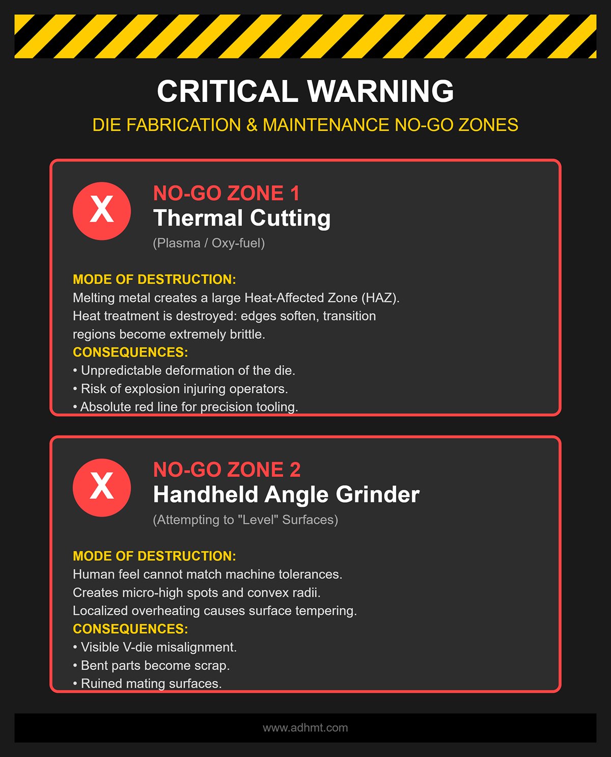
- ❌ No-Go Zone 1: Thermal Cutting (Plasma / Oxy-fuel)
- Mode of destruction: These methods separate metal by melting it, creating a large heat-affected zone (HAZ) on both sides of the cut. Within this zone, the precisely controlled heat treatment of the die is completely destroyed: the edge softens and can no longer carry load, while the transition region may become extremely brittle due to rapid cooling.
- Consequences: In service, the die may deform unpredictably or even explode and injure operators. For precision tooling, this is an absolute red line.
- ❌ No-Go Zone 2: “Leveling” with a Handheld Angle Grinder
- Mode of destruction: Attempting to use a handheld grinder to “true up” and flatten the cut surface.
- Consequences: Human feel can never compete with machine-level tolerances. This approach leaves the mating surfaces of the die with micro-high spots or convex radii. When multiple segments are assembled, you’ll see visible V-die misalignment, and the bent parts will be scrap. In addition, localized overheating from the grinder can cause surface tempering and softening.
- ⚠️ Use with Caution: Pure Waterjet Cutting Without Post-Processing
- The subtle truth: Although waterjet is a cold-cutting process and looks ideal on paper, it has two inherent drawbacks. First, the cut naturally has taper, so the upper and lower dimensions of the die will differ. Second, with ultra-hard tool steels, the jet exhibits lag, leaving a wavy cut surface.
- Conclusion: Waterjet can only be treated as a roughing method, similar to “Route A.” It must be followed by precision grinding to restore proper geometry. It must never be used as a final, ready-to-use finish.
IV. Implementation in the Field: Industrial-Grade Cutting S.O.P. (Standard Operating Procedure)
With the strategy set and the process route selected, we now move into the actual “surgery.” Keep in mind: cutting a press brake die is not just physical separation—it is precision metal surgery. Any misstep can destroy hardness, collapse accuracy, or even cause catastrophic failure in future use.
The following standard operating procedure (S.O.P.) is distilled from real-world shop-floor experience. Strict adherence to these steps is the minimum requirement for a successful die modification.
4.1 Preparation: Datums & Protection
Long before the blade touches metal, success or failure is often already decided. Incorrect clamping will cause the cut to wander, and choosing the wrong datum will leave the cut die unable to align with the backgauge.
- Establish the single “Master Datum” Press brake dies typically have only one or two truly precision surfaces—usually the side of the shank or the back face of the die body. This is your sole reference for setup and alignment on the machine.
- Operating guideline: Use a dial indicator to sweep this datum surface and confirm it is perfectly parallel to the machine’s travel axis (runout should be within 0.05 mm per meter). Never use worn working surfaces—such as the top of the V-opening—as your alignment reference.
- Jaw protection and use of soft jaws Hard-on-hard contact is the enemy of precision machining. Die surfaces are extremely hard and brittle; clamping them directly with hardened vise jaws can easily cause microcracks or crush finely ground faces.
- Operating guideline: Always place copper sheet, aluminum plate, or dedicated soft jaws between the vise and the die. This protects the die surface and increases friction, reducing the risk of part movement due to vibration during cutting.
- Visual layout and marking Do not rely blindly on digital readouts.
- Pro tip: Coat the cutting area with layout dye (Dykem Blue) and scribe an accurate cut line with a height gauge. This is not only a visual aid but also your final safeguard—if the blade does not land exactly on the scribed line, stop immediately and check your setup.
4.2 Rough Cutting: Managing Heat and Stress
Whether you use an abrasive saw or a band saw, the objective in this stage is singular: remove material quickly without compromising the heat-treated condition.
- Controlling the heat-affected zone (HAZ) Heat is the number-one enemy of hardened dies. Localized high temperatures from cutting can anneal the steel near the kerf, softening it so that it collapses under load.
- Core S.O.P.: Use a pulse-cutting technique. Do not maintain constant heavy feed. Instead, work in a “feed in–back out–feed in” rhythm. Each withdrawal allows coolant to flood deep into the kerf and carry heat away.
- Warning sign: If you see the edges of the cut turning blue or purple, the temperature has already exceeded the tempering range. The hardness at that edge is effectively ruined.
- Leaving a “life-saving” allowance When internal stresses are released at breakthrough, the die often twists slightly or springs open, leaving an uneven cut surface.
- Parameter guideline: Never cut directly to final size. For abrasive wheels, leave 1.5–3 mm per side as stock; for band saws, leave about 1 mm. This allowance is for subsequent grinding to remove the heat-affected layer and saw marks.
4.3 Precision Finishing: Giving the Die a Second Life
After rough cutting, the die is only a semi-finished blank. The finishing stage determines whether it can truly perform as a precision industrial tool. This work is typically done on a surface grinder.
- Precision Priority: Shut Height & Parallelism (Shut Height Consistency)
For all segmented dies, the single most critical parameter is uniform shut height. If one segment is just 0.05 mm higher than the rest, the press brake’s tens of tons of force will be concentrated on that tiny area, causing that segment to chip or crack, or leaving heavy damage on the workpiece.- Operating standard: All segmented dies must be ground as a matched set after cutting. Place them side by side on the magnetic chuck and grind the top and bottom surfaces in one setup, ensuring the height tolerance of all segments stays within ±0.01 mm.
- Eliminating Stress Risers: Chamfering & Radiusing
This is the most obvious detail that separates amateurs from professionals. Freshly cut die edges are sharp and full of microscopic notches—classic stress risers just waiting to initiate cracks.- Mandatory requirement: At every junction between cut surfaces and working surfaces, grind in a 0.5–1.0 mm chamfer or radius.
- Why it matters: This is not just about avoiding cut fingers; it is primarily to prevent the die edges from chipping when subjected to lateral loads.
- Demagnetization
Because a magnetic chuck is used during grinding, the dies will retain residual magnetism.- Final step: Use a demagnetizer to fully remove residual magnetism. A magnetized die will attract steel chips, which can become embedded in the sheet surface during bending and cause serious quality defects (impressions/marking).
Master’s Closing Note: At this stage, impatience is extremely costly. In this S.O.P., the time spent on dialing in, cooling, and dressing may easily exceed the actual cutting time of the saw blade. That is precisely why dies processed with this workflow can perform with the same precision and durability as brand-new OEM tooling.
V. Precision Verification Module: Shut Height & Mating Tests
Finishing the cutting work is only the beginning of engineering validation. No matter how shiny the cut faces look, a segmented press brake die that has not passed strict precision checks is a ticking time bomb on the production line.
This module walks you through some of the most demanding industrial acceptance standards to ensure every “cloned” segment works together with the same accuracy and safety as an original one-piece die.
5.1 Controlling Shut Height Consistency
In segmented tooling, shut height uniformity is almost sacred. On a full-length one‑piece die, a small height error may only cause a slight angle deviation. But with segmented dies, if a single segment is just 0.02 mm higher than the rest, the entire tens of tons of hydraulic force at the moment of closure will be focused on that single “high spot.”
The consequences are severe: at best, you get visible marking at that location; at worst, that segment catastrophically fractures from instantaneous overload, and in extreme cases you can permanently damage the press brake’s ram crowning or balancing system.
Industrial-Grade Verification S.O.P.:
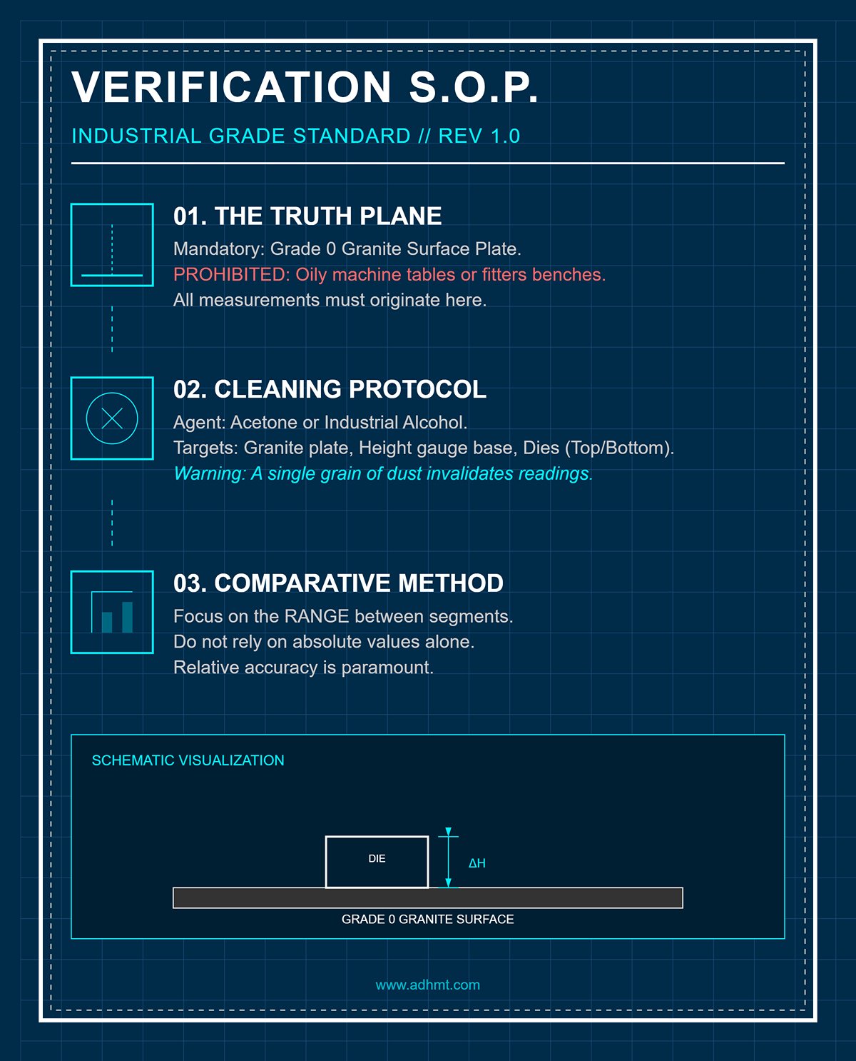
- Establishing the reference plane (The Truth Plane):
All measurements must be taken on a Grade 0 granite surface plate. Never perform this operation on oily machine tables or a fitter’s bench. - Cleaning protocol:
Thoroughly clean the granite plate, the base of the height gauge, and the top and bottom surfaces of all dies to be measured using acetone or industrial alcohol. A single grain of leftover metal dust can invalidate your readings. - Comparative measurement method:
Don’t focus on absolute values alone; what really matters is the range between segments.
- Set up a height gauge or dial indicator and choose the longest die segment as the reference piece, setting its height to “0”.
- Measure each of the shorter, cut segments in turn.
- Acceptance criteria: The height of all segments must fall within ±0.01 mm (0.0004") of the reference.
- Dynamic grouping (Matching):
If you find segments with deviations in the 0.01–0.02 mm range, mark and group them accordingly. When mounting the tooling, never place a segment with positive tolerance (high) directly next to one with negative tolerance (low).
💡 Master-Level Insight — Say No to “Shim Fixes”:
If you see an operator trying to correct height differences by shimming under the die with copper or paper, stop them immediately. This kind of workaround might be acceptable in DIY or hobby use, but in industrial bending it alters the stiffness path of the tool and leads to unstable bend angles. The only proper solution is: send the set back to the surface grinder and regrind all segments to match the lowest one.
5.2 Functional Verification
Passing static dimensional checks does not automatically mean a die is production-ready. Stress relief during cutting can introduce microscopic twists and distortions that are invisible to the naked eye. These must be confirmed—or ruled out—using dynamic tests.
Prussian Blue Mating Test (Contact Pattern Check)
This is one of the oldest yet most effective methods in toolmaking, used to verify whether the punch tip and the V‑die groove are properly aligned without eccentricity or interference.
- Apply blue: Coat the punch tip with an extremely thin layer of engineer’s blue (Prussian blue / Dykem).
- Light contact: Mount the punch and die in the press brake and bring them into alignment. Jog the ram down slowly by hand until the punch tip just kisses both sidewalls of the V‑groove (for acute or gooseneck tooling).
- Evaluate the pattern: Raise the ram and inspect the blue transfer marks inside the V‑groove.
- Pass: The blue forms a thin, continuous, and evenly distributed line on both sides of the V‑groove.
- Fail: Color appears only on one side (indicating twist or misalignment of the backgauge/ram), or the marks are intermittent (indicating uneven grinding or waviness on the cut faces).
Full-Length Test Bend
This is the final “trial by fire.”
- Setup: Assemble all segmented dies tightly together to form a full-length tool.
- Test material: Use sheet stock of the same material and thickness as in normal production, ideally long enough to cover the full segmented length.
- Execution: Perform a single 90° bend.
- Inspection: Using an angle gauge or laser angle meter, measure the bend angle every 50 mm along the part.
- If the angle at the cut locations matches the angles elsewhere, the die modification can be considered successful.
- If you see noticeable angle deviation at or near any cut (for example, angles opening up or closing down), it indicates local softening from heat-affected zones or severe wear. That segment may need to be scrapped or re-hardened.
Only when a set of dies has passed the ±0.01 mm height-uniformity test and demonstrated consistent bending angles across the entire length during trial runs can this “surgically treated” tool be considered truly reborn—and officially approved for service in production.
VI. Conclusion
Successfully cutting a die for a press brake hinges on a systematic engineering approach. From the initial strategic decision and material analysis to modular tool design, process selection, and final verification, each step is critical.
Following this structured path ensures the creation of a precise, durable, and flexible tooling system ready for high-performance fabrication. If you’re looking for proven equipment and engineering support to implement this workflow on your shop floor, ADH Machine Tool provides integrated press brake solutions and tooling optimization services.
Ready to put this guide into practice? For expert consultation on die modification or to explore our advanced press brake tooling, contact us. We're here to help you achieve superior results.


