I. Introduction
1.1 Brief overview of laser cutters
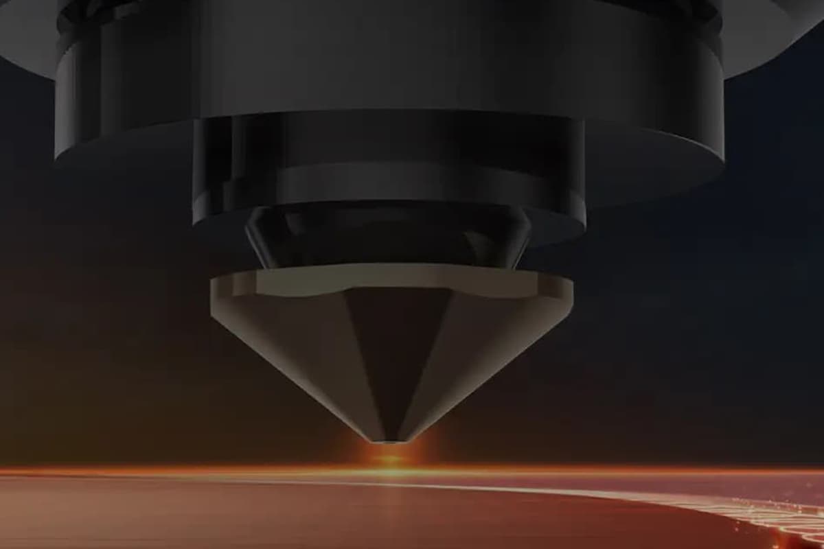
A laser cutting machine is a high-precision and high-efficiency modern manufacturing tool. It utilizes a high-energy-density laser beam as a heat resource to cut the material precisely.
This non-contact processing method makes it widely used in various types of metals and the non-metal manufacturing industry owing to its extraordinary precision, flexibility, and adaptability.
The laser systems are controlled by computer programs, which can achieve complex two-dimensional and three-dimensional rapid prototyping of geometric shapes, greatly improving production efficiency and product quality.
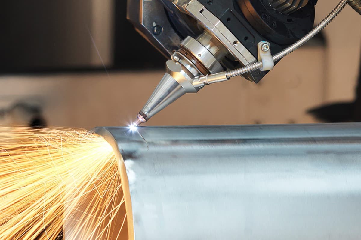
1.2 Introduction to cutting at an angle
In the laser cutting process, normal cutting usually refers to straight or curved cuts perpendicular to the workpiece surface. Many people try to adjust their laser cutters to make perpendicular cuts. However, with the changing of technique advancement and actual needs, laser cutting machine has the function of “cutting an angle”.
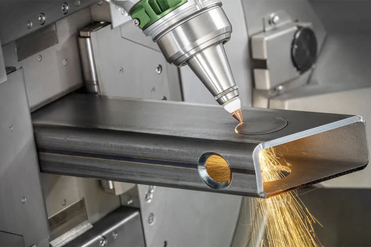
Laser cutters cut angle means cutting the material not at right angles but at an angle. This operation can not only achieve distinctive effects that traditional cutting can not realize but also offers renewed solution plans for structure assembly, welding, and function optimization.
A laser cutting allows for precise cutting. Can laser cutters cut an angle? The answer is yes. A laser cutting machine can cut the material at various angles, achieving intricate designs and precise bevels.
Ⅱ. Core Insights and Cognitive Shift: Breaking the Boundaries of Two-Dimensional Cutting
When discussing whether a laser cutter can perform angled cuts, we must first move beyond the overly simplistic black-or-white mindset. As someone who has worked in precision machining for many years, I can state with confidence: lasers are fully capable of angled cutting, and this technology is redefining welding and assembly standards in advanced manufacturing. However, to understand what’s truly possible, we must first clarify the limits of “can” and the physical trade-offs that come with it.
2.1 The Direct Answer: Yes—or It Depends?
For anyone searching this question, the answer depends entirely on the level of equipment you’re working with. To provide clarity, let’s break it down into three categories:
- Standard 3-Axis Machines (most flatbed lasers): Limited capability. Typical X/Y/Z-axis machines are designed for the laser beam to be perpendicular to the workpiece. While in theory you can tilt the workpiece using custom fixtures to simulate an angled cut, this approach is severely limited by focal range (Z-axis travel) and carries a high risk of head collision. It’s only suitable for small parts or shallow angles. For such machines, the standard verdict is: generally no, unless you apply unconventional modifications.
- Machines with “Bevel Cutting” Capability (2.5D): The industrial entry point. Many mid- to high-end fiber laser cutters—particularly those above the 6kW range—offer optional swinging or 3D cutting heads. These allow the beam to tilt within ±45°, enabling V- or Y-shaped bevel cuts. In this case, the answer is: definitely yes, and with excellent efficiency.
- True 5-Axis Systems and Tube Cutters: The all-round champions. For fully 3D five-axis laser machines or dedicated tube cutting systems, angled cutting is part of their very DNA. They can handle not only slanted planes, but also complex intersections, countersinks, and curved surfaces. Here, the question is no longer “can it cut at an angle?” but rather “can your imagination keep up with the machine’s freedom?”

2.2 Why Is Angled Cutting a Must-Have in Modern Manufacturing?
If lasers were restricted to vertical cuts, manufacturing would pay a heavy hidden cost. The industry’s demand for angled cutting—especially bevel cutting—stems from the drive to compress and streamline processes:
- A Revolution in Weld Preparation (Weld Prep): This is the primary driver. In thick-plate welding (>6mm), vertical cuts often fail to achieve full penetration. Traditionally, the workflow involved “laser cutting → manual or CNC bevel milling → welding.” A bevel-capable laser cutter can produce V-, X-, or K-type bevels in a single pass, combining three steps into one. The result is superior weld strength, consistency, and efficiency compared to manual preparation.
- Greater Design Freedom: Designers can directly create countersunk holes for flush bolt heads, eliminating the need for secondary drilling. In tube and structural fabrication, precise angled cuts enable zero-gap miters, letting components fit together as seamlessly as interlocking blocks.
- Cost Reduction and Efficiency Gains: While machines with angled cutting capabilities require higher upfront investment, industries such as heavy fabrication, shipbuilding, and steel construction usually recover the added cost within 12–18 months through savings in labor, rework, and production time.
2.3 Core Physical Challenges: Effective Thickness and Beam Shape
Now that we understand both the feasibility and the rationale, we must confront the fundamental roadblock: the laws of physics. Angled cutting isn’t simply a matter of rotating the cutting head—it introduces two exponential challenges:
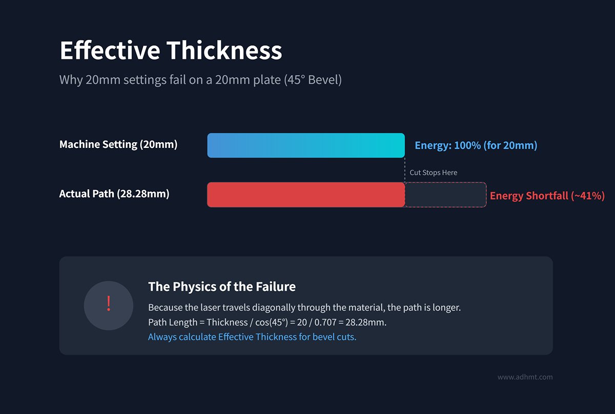
- The “Trigonometric Trap” and Effective Thickness: This is perhaps the most common misconception among beginners. When the cutting head is tilted by an angle $\theta$, the path length the laser must penetrate—its effective thickness $t_{eff}$—changes according to $ t_{eff} = \frac{t}{\cos(\theta)} $. In practice: cutting a 20mm steel plate at a 45° bevel means the laser must actually penetrate 28.28mm of material. You can’t use the same process parameters for a 20mm vertical cut—you’ll need the settings for a 30mm plate. Ignoring this geometric reality leads directly to incomplete cuts and heavy dross accumulation.
- Beam Distortion: A laser beam’s cross-section is typically circular. When it strikes the material perpendicularly, energy is concentrated; when tilted, that circular spot stretches into an ellipse.
- Energy Dilution: As the spot area increases, the power density (W/cm²) drops significantly.
- Quality Instability: The combination of reduced energy density and increased effective thickness compounds quality issues. Hence, advanced angled cutting processes often employ adaptive focusing or beam shaping technologies to compensate for these physical losses.
Chapter Summary: Angled laser cutting isn’t just feasible—it’s an inevitable evolution in advanced manufacturing. However, it demands a shift from “2D planar thinking” to “3D spatial thinking,” along with a deep understanding of how angle affects both material thickness and energy density. Next, we’ll explore the hardware hierarchy and selection strategies that make this process possible.
Ⅲ. Hardware Ecosystem: Equipment Tiers and Selection Strategies for Angled Cutting
From DIY-style “garage modifications” to high-end five-axis systems, hardware capabilities directly determine whether angled cutting becomes a productivity boost or a defect generator. For decision-makers, understanding equipment tiers and physical constraints is the first step to avoiding wasted investment.
3.1 The Workarounds and Limitations of 3-Axis Laser Cutters
For most factories equipped only with standard flatbed (X/Y/Z three-axis) laser machines, the typical response to angled cutting requests (e.g., 45° joints) is to experiment with a “fixture-assisted” approach. While theoretically workable, this method is riddled with practical risks.
- The Fixture Hack—How It Works: Since the cutting head itself can’t tilt, operators build a slanted fixture to lock the workpiece at an angle, effectively letting the laser beam hit the surface “vertically.”
- Fatal Flaws and Hidden Costs:
- Sensor Failure (Capacitive Height Control Breakdown): Standard laser heads rely on capacitive sensors to maintain a constant distance between the nozzle and the workpiece. These sensors are calibrated for flat, horizontal surfaces. When the workpiece is tilted, the nozzle’s sidewall often approaches the surface before the tip does, causing the system to misread height and resulting in catastrophic head crashes, potentially destroying the ceramic body or nozzle assembly.
- Fluid Dynamics Breakdown: The assist gas (oxygen or nitrogen) must be coaxial with the kerf and injected forcefully to expel molten material. When the workpiece is tilted, the downward airflow rebounds sideways—much like water hitting a slide—failing to penetrate the cut effectively. This results in heavy dross buildup at the bottom, or in severe cases, incomplete cuts that compromise quality.
- The Mathematical Deadlock of the Dynamic Z-Axis: A conventional 3-axis machine cannot maintain a straight X–Y trajectory while simultaneously adjusting the Z-axis linearly to match a slope. Unless one manually writes extremely complex G-code, standard nesting software simply cannot generate such three-dimensional toolpaths.
Conclusion: Converting a 3-axis machine for bevel cutting is only suitable for very small production runs with simple straight cuts—and even then, it risks damaging the equipment. For industrial-scale manufacturing, this is not a viable solution.
3.2 Five-Axis Synchronous Systems: The Industrial-Grade Solution
This is where industry leaders like Mazak, Trumpf, and Bystronic compete. True bevel cutting is far more than just adding two extra motors—it represents the deep integration of mechanical engineering and algorithmic control.
- Kinematic Mastery: The RTCP Core Dance: A five-axis system introduces a C-axis (360° rotation around the Z-axis) and a B-axis (head tilting motion). But its true essence lies in RTCP—Rotating Tool Center Point Control. When the B-axis tilts, the laser’s focal point shifts dramatically in physical space. The RTCP algorithm commands the X, Y, and Z axes to make millisecond-level compensations, ensuring that “the head moves, but the focus remains locked precisely on the same point of the material.” Without this algorithm, the moment the head tilts, the focus would drift several millimeters off target.
- The Physics Behind ‘Infinite Rotation’: Many marketing brochures boast of “infinite rotation,” but physics tells a harsher truth. The high-power fiber cable connecting the laser source and the cutting head is as rigid as a hose—if the head were to spin endlessly like a fan, the fiber would twist and snap almost instantly.
- Unwinding Mechanism: Most industrial 3D cutting heads (such as the Precitec ProCutter 3D) can only rotate within ±360° or ±720°. Once they reach that limit, the machine must pause and rapidly reverse-spin to “unwrap” the fiber. This interrupts continuous cutting and reduces efficiency.
- Optical Rotary Joint Technology: A few ultra-high-end systems use optical rotary joints to achieve true continuous rotation. However, this introduces insertion loss—degrading beam quality—and entails significant maintenance costs. As a result, such technology remains uncommon in high-kilowatt lasers.
- Digital Twin Collision Prevention: A five-axis cutting head moves unpredictably through space and can easily strike warped scrap or fixtures. Premium machines therefore come equipped with virtual simulation systems (often based on ModuleWorks algorithms). Before the start button is pressed, the system has already rehearsed 100% of the motion digitally—any potential interference triggers an immediate red alert.
3.3 Dedicated Tube Laser Cutting Machines
This is the most mature domain for angular cutting applications, yet it hides a geometric trap—the single-axis difference between four-axis and five-axis machines can make or break weld quality.
- 4-Axis vs. 5-Axis Tube Cutting: The Geometric Distinction
- 4-Axis Tube Cutting (Perpendicular to Surface): The cutting head always remains perpendicular to the tube’s surface. When cutting a 45°-angled pipe, the wall thickness direction is effectively “straight.” When two such pipes are joined, their inner walls interfere while the outer walls form a wide V-shaped gap—unweldable without extensive manual grinding.
- 5-Axis Tube Cutting (Vertical to Ground / 3D Tilt): The cutting head can remain vertical to the ground or enter at any specified angle. It can produce true intersecting bevel contours, allowing two pipes to mate perfectly along their outer surfaces—achieving “zero-gap fit-up.”
- Revolution in Structural Design: Self-Locating Tabs and Slots: Five-axis tube cutting empowers designers with new freedoms—tab-and-slot structures. By cutting interlocking hooks and slots into tube ends, components snap together like LEGO blocks. Welders no longer need measuring tapes or complex fixtures—just align and weld. This represents a process revolution driven by five-axis technology.

Ⅳ. Decision Analysis: Laser vs. Conventional Machining (Plasma / Milling)
When deciding whether to shift from traditional machining to five-axis laser bevel cutting, one must look beyond the single metric of speed. It’s a multidimensional trade-off involving welding preparation cost, precision requirements, and physical limits. For manufacturing decision-makers, the core question isn’t “Which technology is more advanced?” but rather “Which process achieves the design standard at the lowest total cost of ownership?”
4.1 Multidimensional Comparison: Precision and Quality
Laser cutting is not a cure-all—it occupies a sweet spot between plasma cutting (rough machining) and CNC milling (precision machining). To position it accurately, we must compare across four key dimensions:
| Metric | Five-Axis Laser Cutting (Fiber Laser) | CNC Milling | Plasma Cutting | Decision Key Point (The Hook) |
|---|---|---|---|---|
| Dimensional Tolerance | ±0.05mm ~ ±0.20mm | ±0.01mm | ±0.5mm ~ ±1.5mm | Laser easily meets weldment tolerances, but for close-fitting features (e.g., shafts or keyways), milling is still required. |
| Heat-Affected Zone (HAZ) | Minimal (0.1–0.3mm) | None (Cold Process) | Significant (1.0–3.0mm) | Plasma HAZ must be ground off before welding; laser HAZ is usually weld-ready but may carry microcrack risks. |
| Surface Roughness (Ra) | Ra 6.3µm–12.5µm | Ra 0.4µm–3.2µm | Ra 25µm+ | Laser bevels meet MIG/MAG welding standards, but for high-spec TIG joints, the surface may be slightly too coarse. |
| Oxide Layer | Thin oxide film on cut surface | None | Heavy oxide scale / slag | Note: Even a thin oxide layer from laser cutting can weaken paint adhesion and high-strength welds, so light brushing is still recommended. |
Expert Insight: Perpendicularity and ISO 9013 Compliance It must be noted that as plate thickness increases, the perpendicularity tolerance of laser cutting expands nonlinearly. At a thickness of 20 mm, the vertical deviation of a laser-cut surface may reach 0.5–0.9 mm. While this is perfectly acceptable for weld bevel preparation, it becomes unacceptable if the surface is used as a mechanical positioning reference.
4.2 Financial Analysis: ROI and Investment Return Calculation
To let the numbers speak for themselves, we constructed a “virtual case” based on a typical industrial scenario. Scenario assumption: machining a 20 mm-thick Q355B carbon steel plate to prepare a 45° V-shaped bevel with a total weld length of 100 meters. Note: A 45° bevel means the laser’s actual penetration depth is roughly 28.3 mm, which poses a significant challenge to the equipment.
Cost Comparison Model:
CNC Milling Route (High Quality, Low Efficiency)
- Efficiency: Milling a 20 mm deep bevel requires extremely slow feed rates, approximately 0.2 meters per minute.
- Processing Time: 100 m / 0.2 = 500 minutes (8.3 hours).
- Total Cost: 8.3 h × $80/h (machine cost) = $664.
- Assessment: Exceptional quality but severely consumes expensive machining center time.
Conventional Cutting + Manual Grinding Route (The Hidden Cost Champion)
- Process: Plasma straight cut (very low cost) followed by manual bevel grinding with angle grinders.
- Processing Time: Manual grinding is highly inefficient and performed under harsh conditions—about 1 meter per minute on average.
- Total Cost: Cutting cost (negligible) + 100 h labor × $30/h = $3,000+.
- Assessment: Beyond visible labor costs, this approach carries risks of environmental fines due to dust and inconsistent bevel quality.
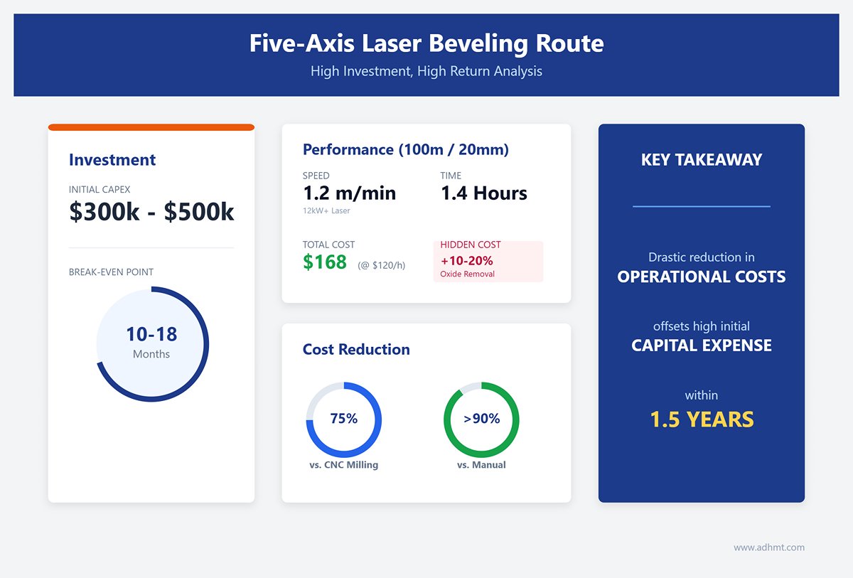
Five-Axis Laser Beveling Route (High Investment, High Return)
- Efficiency: A 12 kW+ laser can cut a 20 mm bevel at roughly 1.2 meters per minute.
- Processing Time: 100 m / 1.2 = 83 minutes (1.4 hours).
- Total Cost: 1.4 h × $120/h (including gas and nozzle wear) = $168.
- Hidden Cost: If oxide removal is required, add about 10–20% for simple post-processing.
ROI Conclusion: For long, straight welds or batch beveling, five-axis laser cutting reduces costs by 75% compared to CNC milling and by over 90% compared to manual grinding. Although the initial investment for a five-axis system ($300k–$500k) is substantial, with sufficient order volume, the break-even point typically occurs within 10–18 months.
4.3 When Not to Use Laser Angle Cutting
Despite its impressive capabilities, laser technology becomes a poor choice when confronted with the following physical limitations:
- “Effective Thickness” Trap: Cutting a 45° bevel on a 30 mm steel plate means the laser path stretches to around 43 mm. This pushes even 12 kW–20 kW lasers to their limit, resulting in severe striations and slag buildup at the bottom. The cutting speed drops to a crawl, quality may fall below fine plasma levels, and lens damage risk skyrockets.
- Fatigue-Sensitive Components: Although laser-cut parts generally outperform plasma cuts in fatigue strength, they can still form micro-hardened layers and fine cracks at high-load stress points—such as crane booms. For ultra-high-strength steels (e.g., S960-grade), milled edges remain the only safe standard.
- Ultra-Precision Fit Surfaces: If a bevel not only serves as a weld interface but also functions as a mounting or alignment surface for bearings or rails, the laser’s roughness (Ra 12.5) and micro-waviness are unacceptable—CNC milling is mandatory.
- Small-Batch, Multi-Variant Production Without Established Parameters: Programming and tuning (Tech Tables) for five-axis lasers are far more complex than for 2D cutting. For single custom parts, engineers may spend more time adjusting nozzle centering, focus offset, and gas parameters than on actual cutting. In such cases, milling or manual grinding may be faster and more practical.
Ⅴ. Practical Pitfall Guide: Common Defects and Solutions
Although five-axis bevel cutting looks perfect on paper, it often turns into a nightmare on the workshop floor. Unlike 2D cutting, 3D operations introduce exponentially more variables. Based on frontline experience, this chapter reveals the hidden traps and real-world fixes not found in equipment manuals—helping you anticipate risks and avoid costly trial-and-error.
5.1 Diagnostic Atlas of Quality Defects
In bevel cutting, defects rarely stem from a single cause—they are the result of complex coupling between geometry, fluid dynamics, and machine kinematics. Below are four of the most typical “hard-to-cure” issues and their respective remedies:
1. Striations and Steps
- Symptoms: The cut surface is uneven—smooth at the top, rough with delayed striations at the bottom, sometimes showing distinct “step-like” layers at certain depths.
- Root Cause Analysis:
- Machine Micro-Vibration: During large-angle (>40°) head tilts, the laser head’s center of gravity shifts rapidly. If the machine gantry lacks stiffness, these micro-vibrations are directly imprinted onto the cut surface.
- Gas Flow Turbulence: When the head tilts, assist gas no longer impacts the surface perpendicularly. Flow separation occurs along the bevel face, reducing slag ejection energy and leaving molten residue behind.
- Remedy:
- Slow and Steady: Reduce feed rate moderately—not only to ensure full penetration but also to stabilize dynamic balance.
- Nozzle Upgrade: Replace standard single-layer nozzles with tapered or high-pressure dual-layer designs to better constrain and direct inclined gas flow deep into the kerf.
2. Incomplete Root Penetration
- Symptoms: A thin uncut “skin” remains at the bevel root; parts may require hammering to separate, and significant slag accumulates at the bottom.
- Root Cause Analysis:
- “Effective Thickness” Miscalculation: This is the most fatal error for beginners. Again, cutting a 45° bevel on a 20 mm plate means the actual path length is 28.28 mm. If parameters are set for only 20 mm, the laser energy will be exhausted midway.
- Focus Shift: During bevel cutting, the focal point—originally set about two-thirds below the material surface—tends to drift along the Z-axis as the cutting path extends and the lens heats up.
- Prescription:
- Parameter Compensation: In the CAM software, enable the “bevel thickness compensation” logic. Use the effective thickness calculated by $t/\cos(\theta)$ to determine the appropriate power and gas pressure.
- Deep Focus Strategy: Manually set a deeper negative focus than used in vertical cutting to ensure the beam waist consistently covers the lower, hard-to-cut zone.
3. Corner Overmelting
- Symptoms: Sharp corners or bends appear scorched and rounded, sometimes with severe pitting around the edges.
- Root Cause Analysis: When a five-axis machine passes through a corner, it must execute a “decelerate–turn–accelerate” sequence. Although the speed drops, if the laser power doesn’t synchronously decrease within milliseconds, the energy density spikes, causing localized overburn.
- Prescription:
- Power Ramping Control: Configure CNC parameters to establish a function linking speed and power—for instance, when speed drops to 10%, power automatically decreases to 15%, with duty cycle adjusted accordingly.
- Corner Looping: Add a small circular lead-in loop at sharp corners so that deceleration and directional change occur in the scrap zone, not on the actual part.
4. Residual Oxide Layer
- Symptoms: The beveled surface appears black or dark blue, with a hardened texture that impairs paint adhesion and causes porosity during welding.
- Root Cause Analysis: This is a natural outcome of using oxygen as an assist gas. On bevel cuts, poor slag removal leads to heat buildup, forming a thicker and more tenacious oxide layer than on vertical cuts.
- Prescription:
- Fundamental Solution: Switch to high-pressure nitrogen (N₂) or compressed air. Though the cut surface may be slightly rougher, oxidation is eliminated, enabling immediate welding after cutting.
- Pragmatic Option: If oxygen must be used (e.g., for thick carbon steel), factor in an additional mechanical finishing process—such as sandblasting or grinding—during cost estimation. This hidden step is indispensable.
5.2 Equipment Maintenance and Hidden Losses
The maintenance logic for five-axis bevel cutters differs completely from that of flatbed machines. Treating a five-axis unit as a flatbed will cut its lifespan in half.
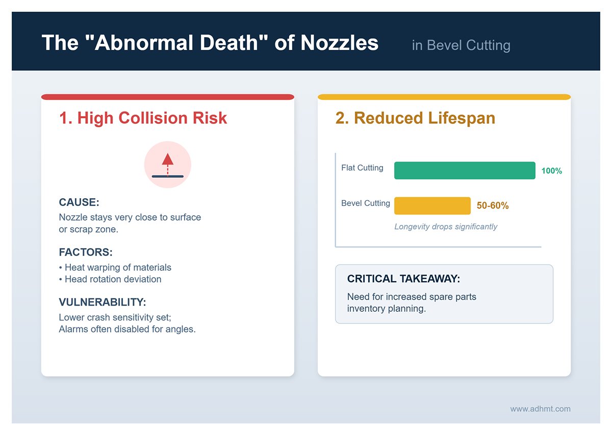
1. The “Abnormal Death” of Nozzles
In vertical cutting, the nozzle maintains a safe distance from the material. However, when cutting V- or K-type bevels, the nozzle often needs to stay close to the surface or even extend into the scrap zone.
- High-Frequency Collisions: If the sheet warps due to heat or the head rotation deviates slightly, the nozzle can easily scrape the material. The crash protection rings on five-axis heads are typically less sensitive than those on flatbed systems, and certain alarms are often disabled to achieve extreme cutting angles.
- Lifetime Warning: Data shows that bevel-cutting nozzles last only 50–60% as long as those used for flat cutting. Spare parts inventory must be planned accordingly.
2. Optical Path Cleanliness: The Z-Axis “Bellows Effect”
This is an often-overlooked killer. During flat cutting, Z-axis movement is minimal. But in five-axis operation, the Z-axis bellows undergo large, frequent compressions and extensions.
- Dust Infiltration Nightmare: This vigorous motion acts like a giant lung, creating negative pressure that sucks metallic dust into the optical housing. Even slight seal damage can ruin expensive focusing and protective lenses within days.
- Preventive Advice: Maintain positive pressure protection inside the cutting head (typically dry, clean nitrogen) and enforce a strict weekly inspection routine for the Z-axis bellows integrity.
3. Essential Anti-Spatter Pre-Treatment
When performing large-angle piercing, molten dross tends to eject sideways rather than downward, adhering to the workpiece surface or the sidewalls of the cutting head.
- Operational SOP: Before bevel cutting high-reflective or thick materials, spray anti-spatter fluid near the piercing point. This minor consumable cost saves substantial labor in post-cleaning and protects expensive cutting head components.
Ⅵ. Industry Application Case Library: Beyond Theory
Laser bevel cutting technology has long moved beyond laboratory trials to become a core force reshaping manufacturing processes across major industrial sectors. The following real-world cases illustrate how theoretical feasibility translates into measurable financial competitiveness.
6.1 Heavy Machinery and Steel Structures
In heavy industry dealing with thick and high-strength materials, laser bevel cutting is far more than an upgrade to cutting tools—it revolutionizes the traditional “blanking + machining” production chain.
Case 1: One-Step V-Bevel Cutting of High-Strength Steel Excavator Buckets In construction machinery manufacturing, bucket blades are typically made from abrasion-resistant steel such as Hardox 500. The traditional process—“plasma straight cut → manual/semi-automatic bevel grinding”—is both costly and inconsistent, leading to unstable weld penetration. Introducing high-power five-axis laser cutting enables one-step ±45° V-bevel formation.
- Efficiency Boost: Bevel processing time per piece dropped from 45 minutes to 25 minutes, improving overall efficiency by approximately 40%.
- Quality Transformation: Laser-cut surfaces are exceptionally smooth, eliminating secondary grinding and ensuring stable weld seams free from slag inclusions caused by uneven bevels.
Case 2: Complex Node Cutting in H-Beam Steel Structures In large-scale structural engineering, intersections between H-beams and round tubes are major pain points. Conventional designs rely on numerous gusset plates and bolts, making assemblies heavy and cumbersome. Using advanced profile laser systems (e.g., BLM Group solutions), one steel structure firm adopted an innovative 3D cutting approach—directly shaping intricate tooth joints and variable bevels at the beam ends, allowing precise interlocking similar to traditional mortise-and-tenon joints.
- Data Results: The project achieved 63% material savings and 62% cost reduction.
- Schedule Compression: Node machining and assembly dropped from 3–4 days to single-shift completion, with weld strength meeting EU EN 1090 structural steel standards—demonstrating laser cutting’s reliability for load-bearing structures.
6.2 Aerospace and Automotive Manufacturing
For industries that demand extreme lightweight construction and superior material performance, laser bevel cutting addresses long-standing challenges that conventional machining cannot overcome—specifically, the difficulty of processing high-hardness materials and the frequent wear of cutting tools.
Case 3: 3D trimming and hole processing for automotive hot-stamped components (PHS) As vehicle safety standards continue to rise, high-strength hot-stamped steel—reaching tensile strengths above 1500 MPa—is now widely used for critical areas such as the A- and B-pillars. With hardness up to HRC 50, traditional stamping dies tend to chip after only a few operations, leading to excessive maintenance costs. The five-axis 3D laser trimming machine has therefore become standard equipment on these production lines. Test data from a major German automaker shows that using a five-axis laser head for 3D contour trimming and hole cutting yields remarkable improvements:
- Speed comparison: Processing time for a single B-pillar dropped dramatically—from 8 minutes with conventional CNC milling to just 90 seconds.
- Precision assurance: Hole positioning accuracy remains stable within ±0.1 mm, fully meeting the tolerance requirements of automated body assembly lines. A single production line needs only 3–5 laser units to meet capacity demands, significantly reducing floor space requirements.
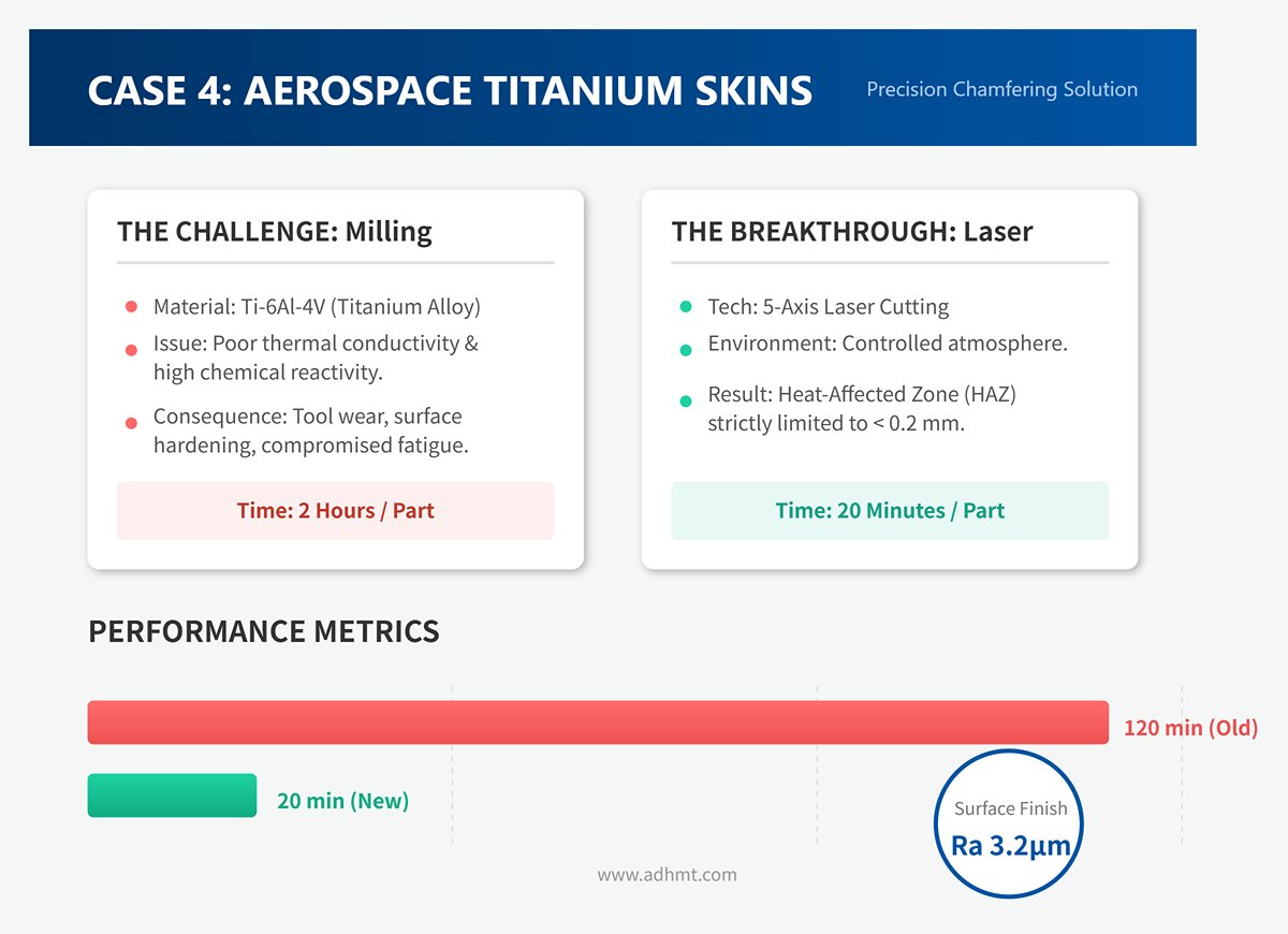
Case 4: Precision chamfering of aerospace titanium alloy skins In aircraft manufacturing, titanium alloy (Ti-6Al-4V) skin edges require precise 45° chamfering to eliminate stress concentrations. Because titanium’s poor thermal conductivity and high chemical reactivity accelerate tool wear and surface hardening during conventional milling, fatigue strength can be compromised.
- Process breakthrough: By using five-axis laser cutting in a controlled atmosphere, the heat-affected zone (HAZ) is strictly limited to under 0.2 mm.
- Results: The cut surfaces meet aerospace-grade finish standards (Ra 3.2 μm) without deburring. Processing time per part dropped from 2 hours (milling plus manual finishing) to just 20 minutes.
6.3 Energy and Pipeline Engineering
Case 5: Saddle-cut joints for oil pipelines—achieving zero-gap fits In oil and gas pipeline fabrication, branch pipes must connect to main pipes through complex saddle-shaped intersection cuts. Traditionally, workers used handheld flame cutters with paper templates, followed by extensive grinding and finishing. Each large-diameter joint often took over an hour to complete, with fit gaps exceeding 2–3 mm—severely affecting weld quality.
- Technological innovation: The introduction of five-axis tube laser cutters allows the machine to automatically generate variable-angle cutting paths from CAD models, keeping the cutting head either perpendicular to the pipe wall’s tangent or tilted according to welding requirements.
- Economic benefits: According to real-world data from Hill Mfg, in a project involving 77 ten-inch manifolds, laser saddle cutting kept fit gaps within 0.5 mm (achieving true zero-gap assembly) and reduced cutting time per joint to 5–6 minutes. The overall project timeline was shortened by more than 14 days, saving over $16,000 in total costs.
Ⅶ. Future Outlook and Action Recommendations
Having explored the underlying physics, hardware selection, and practical applications, we now stand at a crossroads of technological evolution. The next step is not only to ask “Can we cut it?” but also to understand “How will we cut it in the future?”—providing a rational compass for today’s investment decisions.
7.1 Technological Frontiers: From Automation to Intelligence
Laser cutting is transitioning from the stage of “following the blueprint” automation to the era of “adaptive response” intelligence. For companies aiming to secure long-term competitiveness, the following two cutting-edge developments are redefining the boundaries of bevel cutting.
1. AI Adaptive Control: Giving the Cutting Head a Brain Traditional bevel cutting relies heavily on operator experience—when surface rust or material inconsistencies occur, fixed parameter tables fail, producing flawed cuts.
- Vision-based closed-loop control: The latest intelligent cutting heads integrate coaxial vision sensors or spectrometers that monitor the melt pool’s color, temperature, and spatter patterns thousands of times per second.
- Dynamic adjustment: When AI detects excessive melt pool temperature (risk of overburn) or abnormal spatter (risk of incomplete penetration), it no longer merely alerts operators—it automatically fine-tunes laser power, gas pressure, and feed rate within milliseconds. This means even novice operators can achieve expert-level bevel quality under AI guidance.
2. Hybrid Machining Centers: Breaking Process Barriers The concept of “one machine equals one factory” is becoming reality in the laser sector. The traditional workflow—“laser cutting → transfer → CNC finishing”—is being replaced by integrated hybrid systems.
- Integrated additive–subtractive processing: New hybrid centers combine five-axis laser cutting with CNC milling spindles. For surfaces requiring ultra-high precision, the laser first removes about 95% of material rapidly, followed by micron-level finishing with the same machine’s milling tool.
- Value proposition: This eliminates repositioning errors from secondary setups and compresses lead times by over 60%. Such systems are ideal for high-value aerospace components requiring “one-shot” precision manufacturing.
7.2 Final Recommendations for Buyers and Engineers
Investments in this field often reach hundreds of thousands of dollars, and avoiding costly trial-and-error is critical. The following decision toolkit is distilled from extensive real-world experience.
✅ The Ultimate Equipment Selection Checklist (The Buyer’s Checklist)
Before negotiating with suppliers, review these core criteria—they determine success far more than headline specifications like maximum power.
| Core Dimension | Key Self-Check Question | Expert Insight |
|---|---|---|
| Bevel Limit | Do you require a maximum angle of 45° or 60°? | 45° is the critical threshold. Angles beyond 45° demand specialized cutting head designs and more complex anti-collision logic, which significantly increase equipment costs. |
| Z-Axis Travel | Is there sufficient vertical clearance for the cutting head? | A frequently overlooked parameter. Large-angle cuts require substantial clearance. If Z-axis travel is too short, deep cavities or complex pipe joints cannot be processed. |
| Software Intelligence | Can the CAM software automatically generate “avoidance paths” and “thickness compensation”? | Hardware defines the upper limit, software defines the lower limit. Advanced software calculates t / cos(theta) automatically and adjusts parameters without manual intervention. |
| Power Redundancy | Have you selected power based on “effective thickness”? | For a 45° bevel on a 20 mm plate, the actual optical path approaches 30 mm. Do not size power by physical thickness alone—reserve 30–50% power redundancy. |
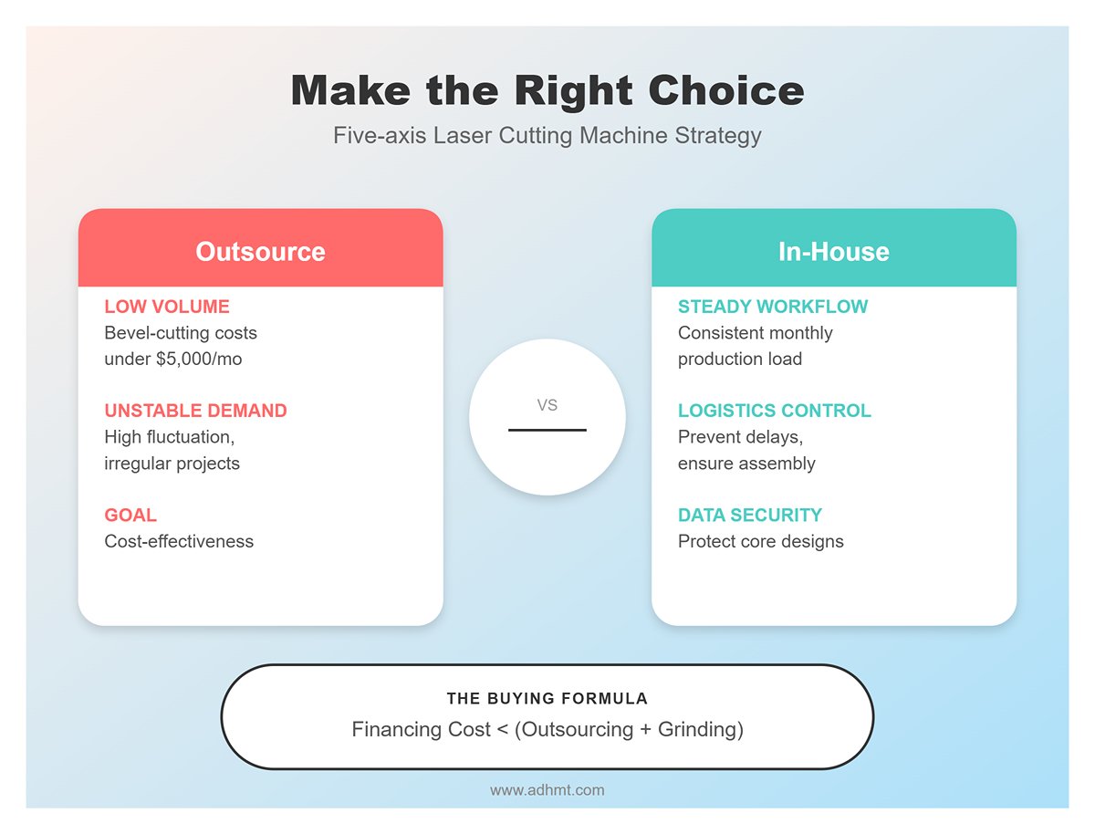
📊 Decision Model: Outsourcing or In-house Production?
Not every factory needs its own five-axis laser cutting machine. Consider the following thresholds:
- Recommendation: Outsource: If your monthly bevel-cutting expenses are below $5,000, or your demand fluctuates greatly (e.g., only one major project every six months), leveraging specialized service providers is the most cost-effective strategy.
- Recommended In-house Production: If your beveling workload is steady each month and outsourcing frequently causes logistics delays that disrupt assembly progress, or if your products involve confidential core designs, bringing production in-house becomes advantageous. When the monthly equipment financing cost falls below your current outsourcing fees plus manual grinding expenses, that’s the ideal moment to invest in your own machine.
📝 Appendix: Quick Reference Table — Angle, Thickness & Power
To give you a clearer sense of the “physical limits,” here’s a typical parameter reference table based on carbon steel materials. The data is for general guidance only, as exact values vary by equipment brand.
| Physical Plate Thickness (mm) | Cutting Angle (°) | Effective Laser Penetration Thickness (mm) | Recommended Power (kW) |
|---|---|---|---|
| 10 | 30° | 11.5 | ≥ 3 kW |
| 10 | 45° | 14.1 | ≥ 4 kW |
| 20 | 30° | 23.1 | ≥ 8 kW |
| 20 | 45° | 28.3 | ≥ 12 kW |
| 25 | 45° | 35.4 | ≥ 20 kW |
VIII. Conclusion
In most cases, the laser cutters will cut at an angle close to 90 degrees (a slight angle). Featuring its prominent advantages, laser cuts at an angle play an increasingly important role in modern manufacturing.
In our passage, we talk about the precision and accuracy of angle-cutting. This technology can achieve high precision and high-quality angle-cutting, which can greatly meet the complex angle-cutting requirements for aerospace, automotive manufacturing, and other precision components. Compared with the traditional cutting method, laser cutting at an angle performs well in time and cost.
Automatic control and high-efficiency fabrication processing can effectively decrease production costs and improve overall efficiency. Meanwhile, reducing material waste is also a prominent advantage, which can maximize resources and sustainable production advancement. What’s more, even laser cutters at an angle are faced with heat deformation and material warping.
With technology innovation and crafts improvement, such as dynamic focusing, intelligent control systems, and the development of composite processing technology, these problems are being solved, increasingly expanding the laser angle cutting application scope and capacity limit.
If you want to find a laser cutting service and get a good and efficient alternative, please visit our official website or contact our salesman for details.
IX. FAQs
1. What are the practical applications of angle cutting?
Angle cutting with laser cutters is widely used across industries. It improves joint strength in welding, enables precise geometries in aerospace and automotive manufacturing, and enhances aesthetic and functional designs in architecture, furniture, and medical devices.
2. How can I optimize laser cutter settings for angle cuts?
To optimize laser cutter settings for angle cuts, consider material properties, thickness, and techniques like bevel and tilt. Adjust the laser beam and lens focal length to maintain precision. Mitigate heat distortion and warping through focus, power control, and cooling.
Use CAD software for cutting paths and calibrate the cutting equipment for consistency. Fine-tune laser power, speed, and focal length based on material for high-quality cuts.
3. What should I consider when selecting materials for angle cutting?
When selecting materials for laser angle cutting, consider properties like strength, durability, and thermal behavior, as these affect cut quality. Thickness and density are key, with thicker materials needing higher laser power and slower speeds. Check flammability and heat sensitivity to avoid warping. Prioritize economical, standard thickness materials and ensure compliance with safety standards.


