How to decrease material warping on a CNC press brake? The answer lies in a systematic, engineering-based approach that addresses the root causes of deformation. This guide provides that strategy, detailing how to control warping through material selection, hardware optimization, and intelligent process programming.
We will explore everything from grain direction and tooling choices to the advanced closed-loop systems that are defining the future of precision bending.
I. Cognitive Reframing: Redefining Bend Warpage and Its Hidden Costs
In precision sheet metal fabrication, post-bend warpage is often casually dismissed on the shop floor as an occasional “flatness issue,” or blamed on “bad luck” with a defective batch of material. This mindset dramatically underestimates its destructive impact. In a world-class manufacturing system, warpage is not just a geometric defect; it is the inevitable physical manifestation of internal material stresses “pushing back” against the forming process, and it acts as a silent cost multiplier lurking along the production line. To truly address it, we must first completely reconstruct our understanding from two perspectives: its physical origins and its economic consequences.
1.1 Deconstructing the Phenomenon: It’s More Than Just “Bent”
To genuinely control warpage, we need to abandon vague descriptions like “the part is bent” and break it down into several distinct physical forms, each driven by different mechanical mechanisms. At its core, warpage is the result of residual internal stresses seeking a new equilibrium once the external constraint (the die) is removed.
Physical Root Cause: An Unbalanced “Stress Sandwich”
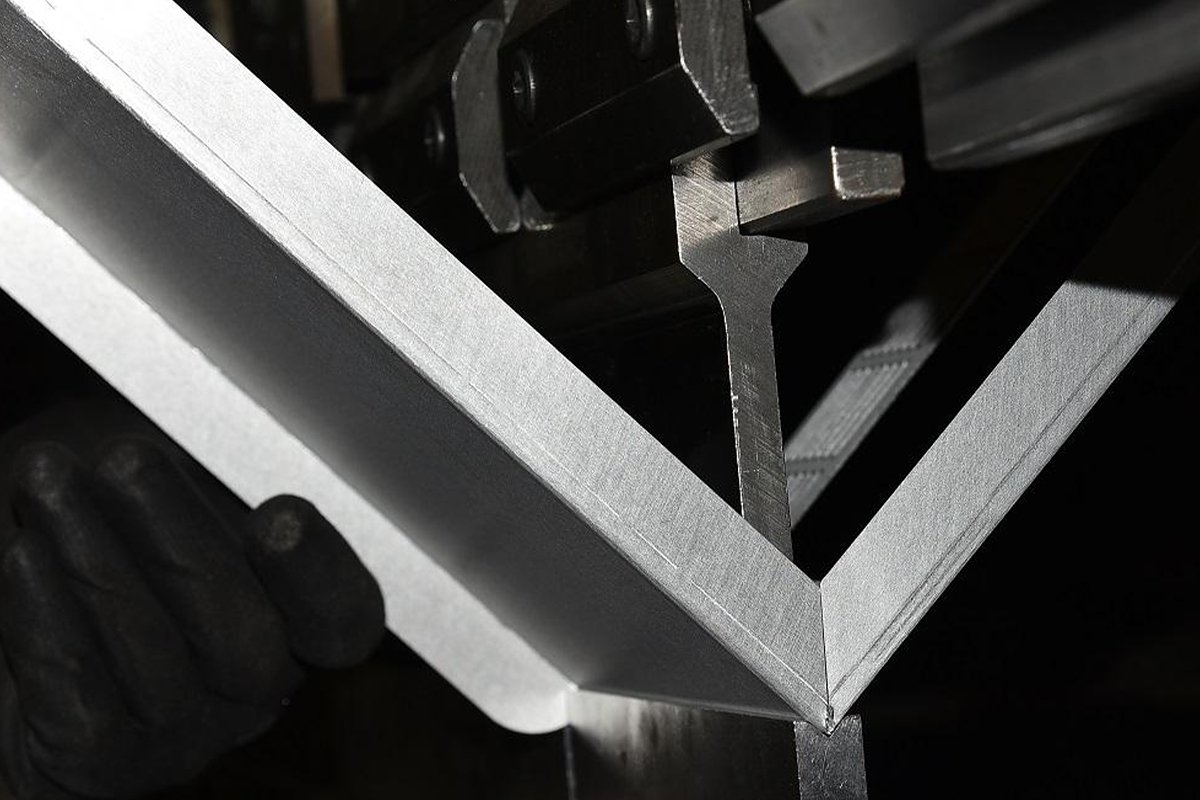
When a metal sheet is driven into a V-die, its thickness direction undergoes intense micro-scale tearing. The outer fibers are forcibly stretched, creating tensile plastic deformation; the inner fibers are heavily compressed, creating compressive plastic deformation; only a narrow “neutral layer” in between experiences neither tension nor compression. After bending, this “stress sandwich” made up of outer tensile stress, a neutral layer, and inner compressive stress does not simply vanish. Once the load is released, elastic recovery (springback) kicks in: the stretched outer layer tries to contract, while the compressed inner layer tries to expand. This internal “tug-of-war” generates a reverse bending moment that directly gives rise to four typical warpage modes:
- Bowing / Camber: The most common form, where the part curves like a bow along the bend line. The usual culprit is uneven stress relief distributed along the bend line.
- Twisting: The two ends of the part no longer lie in the same plane, resembling a wrung towel. This is especially prevalent in asymmetric parts or when the material grain/orientation is poorly controlled.
- Oil Canning: A nightmare for appearance engineers. Flat panel areas develop wavy, pressable “pillow” regions. This is a direct manifestation of local buckling caused by residual compressive stress within the sheet and is the number one killer of Class-A cosmetic surfaces.
- Angular Variation: The bend angle varies along the length of the bend line (for example, 90° at one end and 91° at the other). This is a direct symptom of non-uniform springback and is often mistakenly attributed to poor machine accuracy.
1.2 The Silent Cost: How Warpage Disrupts the Entire Manufacturing Chain
The real danger of warpage is not the scrap cost of a single metal sheet, but the Cost of Poor Quality (COPQ) it triggers. Industry data indicate that such hidden costs can reach 15–20% of total company revenue. Warpage behaves like a virus, propagating downstream along the value chain and amplifying its damage at every stage.
Impact 1: The Welding Station—An “Efficiency Black Hole”
When two warped parts are forced to fit together, the precisely designed weld seam turns into an irregular gap.
- Exploding Consumables Usage: To bridge these gaps, welders must deposit significantly more filler metal. Data show that when the gap in a fillet weld increases from 0 to 3.2 mm (1/8 inch), the amount of filler metal required to achieve the same strength jumps by 124%.
- A Vicious Cycle: More filler means higher heat input, which in turn causes greater weld distortion. This traps production in a destructive loop of “warpage → weld distortion → even more warpage.”
- Automation Killer: For robotic welding, irregular gaps are fatal. They cause frequent alarms and stoppages or force the company to invest in expensive laser seam-tracking systems, dramatically slowing production takt time.
Impact 2: The Assembly Station—“Brute-Force Engineering”
In final assembly, warpage means parts no longer drop into place naturally. Assemblers are forced to resort to hammers, locking pliers, crowbars, and other tools to forcibly straighten and clamp parts into position. This not only consumes time, it also locks large, unpredictable assembly stresses into the product. These trapped stresses become hidden time bombs, leading to long-term distortion, loosening fasteners, or even fatigue fractures in service.
Impact 3: The Paint Shop—Where Defects Are Exposed
Minor oil-canning may be barely visible on bare metal, but once a high-gloss coating is applied, light reflection exaggerates every ripple. The surface begins to resemble disturbed water, instantly degrading the perceived quality of the product and triggering customer rejections.
💡 Expert Insight: The “Tolerance Stack-Up” Effect
The most insidious cost of warpage lies in tolerance accumulation. A 1 mm warp on a single part may still fall within its drawing tolerance and appear “acceptable.” But when 20 such parts are assembled in the same direction, the cumulative deviation can reach a shocking 20 mm. This is why many designs that look flawless in CAD become impossible to assemble on the shop floor.
With this understanding, a clear consensus emerges: controlling warpage is not about aesthetics; it is about protecting manufacturing efficiency and profitability.
II. Physical Root Causes: Drilling Down to the Micro-Mechanisms of Deformation
The seemingly “unruly” warpage behavior of bent parts is not the result of operator “bad luck” or mysterious forces. It is the combined effect of several powerful mechanisms deeply rooted in basic material mechanics. Without understanding these physical foundations, any parameter tweaking is mere guesswork. To achieve precise control over warpage, we must first zoom into the micro world and observe the silent battle taking place inside the metal.
2.1 Stress Release and Equilibrium
This is the most fundamental and direct cause of warpage—especially springback and bowing along the length of the bend. In essence, it is a micro-scale “tug-of-war” inside the material once external constraints are removed.
- The “Stress Sandwich” Model: When we force a metal sheet into a V-die, the material through the thickness is subjected to drastically different conditions, forming a complex “stress sandwich” structure.
- Outer Layer (Tension Zone): Fibers are forcibly elongated, generating tensile stress.
- Inner Layer (Compression Zone): Fibers are heavily squeezed, generating compressive stress.
- Neutral Axis: A transitional layer in the middle that experiences neither tension nor compression.
The key point is that these stresses have two components: permanent plastic deformation and stored elastic deformation. The elastic portion behaves like countless tiny springs, stretched or compressed and loaded with potential energy.
- The “reverse bending moment” at unloading: The instant the upper punch lifts and the external pressure (constraint) disappears, all those locked-in “elastic springs” try to release their stored energy. The tensile springs in the outer layer attempt to contract, while the compressed springs in the inner layer try to expand. These two opposing forces generate an internal reverse bending moment in the material. This moment is what drives the part to “spring back” until the internal residual stresses reach a new equilibrium. If this reverse moment is not evenly distributed along the bend line (typically due to material inhomogeneity or residual rolling stress), the part will exhibit a noticeable bow or camber on the macroscopic level.
2.2 Poisson’s Effect
If stress equilibrium explains deformation along the bend direction, then Poisson’s effect reveals the often-overlooked three-dimensional deformation that occurs perpendicular to the bend direction. This is the underlying physical cause behind “saddle-shaped” parts or parts that sag in the middle with both ends lifting up.
- Mechanism of transverse deformation: Poisson’s ratio is the elastic constant that describes the relationship between transverse strain and axial strain when a material is subjected to tension or compression. In simple terms, when you stretch a rubber band, it becomes thinner; when you compress it, it becomes thicker. During bending:
- Outer layer in tension: According to Poisson’s effect, the outer layer will shrink (become narrower) in the direction perpendicular to the bend line.
- Inner layer in compression: The inner layer will expand (become wider) in the direction perpendicular to the bend line.
- “Saddle-shaped” anticlastic curvature: This “narrower outside, wider inside” size mismatch prevents the bent flange from remaining straight. Instead, a secondary distortion occurs: the center of the sheet sinks inward while the side edges curl upward, creating a saddle-like profile. In academic terms, this phenomenon is known as anticlastic curvature. It is particularly prominent when bending wide plates and directly destroys the straightness of the bend edge, making it very difficult to eliminate gaps during subsequent welding and fit-up.
2.3 The physical inevitability of press brake deflection
This is the equipment-level physical root cause of the “banana effect” or “canoe effect,” where long parts end up with a larger angle in the middle and smaller angles at both ends. It exposes a harsh manufacturing reality: there is no such thing as a perfectly rigid press brake.
- Elastic deformation of a beam: A press brake is essentially a massive beam structure made up of an upper ram and a lower bed. When the hydraulic cylinders apply tens or even hundreds of tons of force at both ends, mechanics of materials tells us that the central portion of the machine, lacking direct rigid support, will inevitably undergo micron-level elastic deflection. The ram bows slightly upward and the bed sags slightly downward, forming the well-known “smile curve.”
- The error propagation chain for angle variation: This barely visible machine deflection triggers a chain reaction:
- Gap variation: The actual distance between the upper and lower tools is larger at the machine center than at the ends.
- Effective V-opening increases: Physically, this is equivalent to the V-die opening being wider at the center section.
- Angle deviation: In air bending, a wider V-opening means that, at the same penetration depth, the material will form a blunter (larger) angle.
The end result is that, after a single bend on a long part, the angle in the middle may be 91° while the ends are 90°. Over a long flange, this angular difference is magnified and manifests as severe overall bowing. This is the unforgiving verdict of physics on machine rigidity, and the fundamental reason why you cannot achieve high-precision bending on long parts without a crowning or deflection compensation system.
III. Strategy One: Control at the Material Source (Material & Pre-process)
Among all the complex techniques for controlling distortion, the most effective and fundamental measures usually start long before the part ever reaches the press brake. Many operators focus all their effort on endlessly tweaking machine parameters, while overlooking a brutal truth: if you are working with a sheet whose internal stresses are chaotic and whose condition is poor, even the most expensive press brake in the world cannot guarantee flatness.
Instead of passively “correcting” warpage downstream, it is far better to proactively “design” the material’s behavior at the source. This is the core idea behind source-level control.

3.1 Grain Direction Strategy
This is perhaps the most important yet most frequently overlooked “unwritten rule” in sheet metal design and fabrication. Sheet metal is not isotropic; it has a distinct “personality” — anisotropy. The root cause is the directional “grain” formed as metal crystals are stretched during the rolling process.
- The “golden rule”: Always bend perpendicular to the grain direction This is the undisputed first rule in sheet metal bending. When nesting parts on a sheet, you must do everything possible to ensure that the bend lines are perpendicular to the grain direction (across the grain).
- The physics behind it:
- Perpendicular bending (across the grain): When the bend line cuts across a large number of elongated grains, the stress is spread relatively evenly among them. The material then exhibits its best toughness: it can withstand a smaller bend radius without cracking, and its springback is smaller and more consistent.
- Parallel bending (with the grain): When the bend line runs parallel to the more fragile grain boundaries, the stress concentrates along just a few grain boundaries. This is like splitting firewood along the grain — the outer layer is far more likely to crack, especially with small bend radii or low-ductility materials. Even worse, springback in this direction is usually larger and less predictable, greatly increasing the risk of twist and distortion.
- The physics behind it:
- Priority in strategic choices: To minimize the risk of warpage and distortion, follow this decision hierarchy:
- Optimal choice (90°): Bend line perpendicular to the grain direction. This produces the strongest, most reliable bends and is the first choice for precision sheet metal.
- Second-best choice (45°): Bend line at a diagonal to the grain. Performance is intermediate between the best and worst cases and is usually an acceptable compromise when trying to improve material utilization.
- High-risk choice (0°): Bend line parallel to the grain direction. Avoid whenever possible. If design or cost constraints force you to bend this way, you must compensate by using a bend radius much larger than usual (a common rule of thumb is at least 1.5 times the material thickness) to reduce tensile strain in the outer fibers and lower the risk of cracking and warpage.
3.2 Material Pre-treatment and Condition Management
The core of this strategy is to use a series of pre-processing “conditioning” steps so the material enters the press brake in the most “relaxed” and “cooperative” state possible.
- Pre-treatment method 1: Precision leveling to release internal stress Coils and plates straight from the mill inherently “store” residual stresses created during rolling and cooling. These invisible stresses are the main culprits behind plate deformation after laser cutting and the “oil-canning” effect that appears after bending.
- Standard leveling (Flattening): Improves only the visible flatness of the sheet and does not address deeper internal stresses.
- Precision leveling: This is the real “pre-treatment” step.
- Roller leveling: The sheet passes through a set of precisely arranged, small-diameter rollers in an alternating upper–lower pattern. By repeatedly bending the sheet with small deflections beyond its yield point, the internal, irregular stresses are equalized and released.
- Tension/Stretcher leveling: A more advanced technique. A large longitudinal tensile force is applied to the sheet, causing a slight, permanent elongation (typically about 1–3%). This “forced reset” eliminates virtually all internal stress and delivers exceptional flatness. Sheets processed this way are often called “zero‑stress” material and are the ideal base stock for high‑precision bending.
- Pre-treatment method 2: Stress-relief annealing For thick plate or parts that have undergone extensive cold working (such as dense punching), performing stress-relief annealing before bending is the “ultimate weapon” against warpage. By heating the material to a specific temperature (below the phase transformation point) and cooling it slowly, you can largely release the work hardening and residual stresses accumulated during cutting, stamping, and other upstream processes, restoring a uniform mechanical state.
- Condition management: Leveraging the wisdom of age hardening For heat-treatable aluminum alloys (such as 6061, 2024, etc.), an extremely effective strategy is “form soft, use hard.”
- Key operating idea: Purchase aluminum sheet in the T4 temper (solution heat treated and naturally aged) for bending. In this state, the material is relatively soft, has excellent ductility, is easy to form without cracking, and exhibits minimal springback.
- Strengthening after forming: Once the part has been fully bent to shape, place it in a heat-treatment furnace for artificial aging, bringing it up to the high‑strength T6 temper.
- Value: This approach neatly avoids the large springback and warpage tendencies associated with bending high‑strength material, while still delivering high final strength. It is standard practice in aerospace and high‑end electronic enclosure manufacturing.
- 💡 Expert insight: The Bauschinger Effect This deep mechanical effect reveals how materials “remember” and “tire,” and is a hidden reason why warpage in complex bends is so hard to predict.
- Phenomenon: When a metal has undergone plastic deformation in one direction (for example, in tension), its yield strength in that direction increases (work hardening), but its yield strength in the opposite direction (such as compression) drops significantly.
- Impact on bending: Bending is inherently a complex stress cycle of “tension on the outside, compression on the inside.” If the sheet has been leveled (repeatedly bent) before forming, the Bauschinger Effect makes its mechanical response nonlinear and highly complex. This explains why scrap that has been straightened and re-bent multiple times starts to behave in increasingly odd and unpredictable ways.
- Takeaway: A material’s “history” changes its “nature.” The importance of forming in a single pass speaks for itself—every unnecessary correction or trial bend consumes some of the material’s predictability and increases the risk of final warpage.
IV. Strategy Two: Machine Accuracy & Tooling Engineering
If the material is the “soldier” on the battlefield, then the machine and tooling are the “commanders.” Even with the most flawless, stress‑free sheet, warpage is still inevitable if the hardware suffers from rigidity issues or the tooling strategy is flawed.
In this section we move our focus from the material’s interior to the external physical environment, examining how to build a rigid defense line against distortion by optimizing the press brake’s dynamic compensation and the engineering design of the tooling.
4.1 In-depth look at crowning systems
Under hundreds of tons of bending force, even a “steel beast” of a press brake must bow to the laws of physics. Micron‑level elastic deflection of the ram and bed is inevitable, and it is this deflection that causes the classic “canoe effect”: larger angles in the middle of long parts and smaller angles at the ends. The heart of modern CNC press brake crowning systems is not simply to increase machine stiffness, but to apply a counter‑deflection of equal magnitude and opposite direction at the very moment deformation occurs—using “softness to overcome stiffness” to maintain straightness dynamically.
Understanding the characteristics of different crowning technologies is essential for developing anti‑warpage strategies:
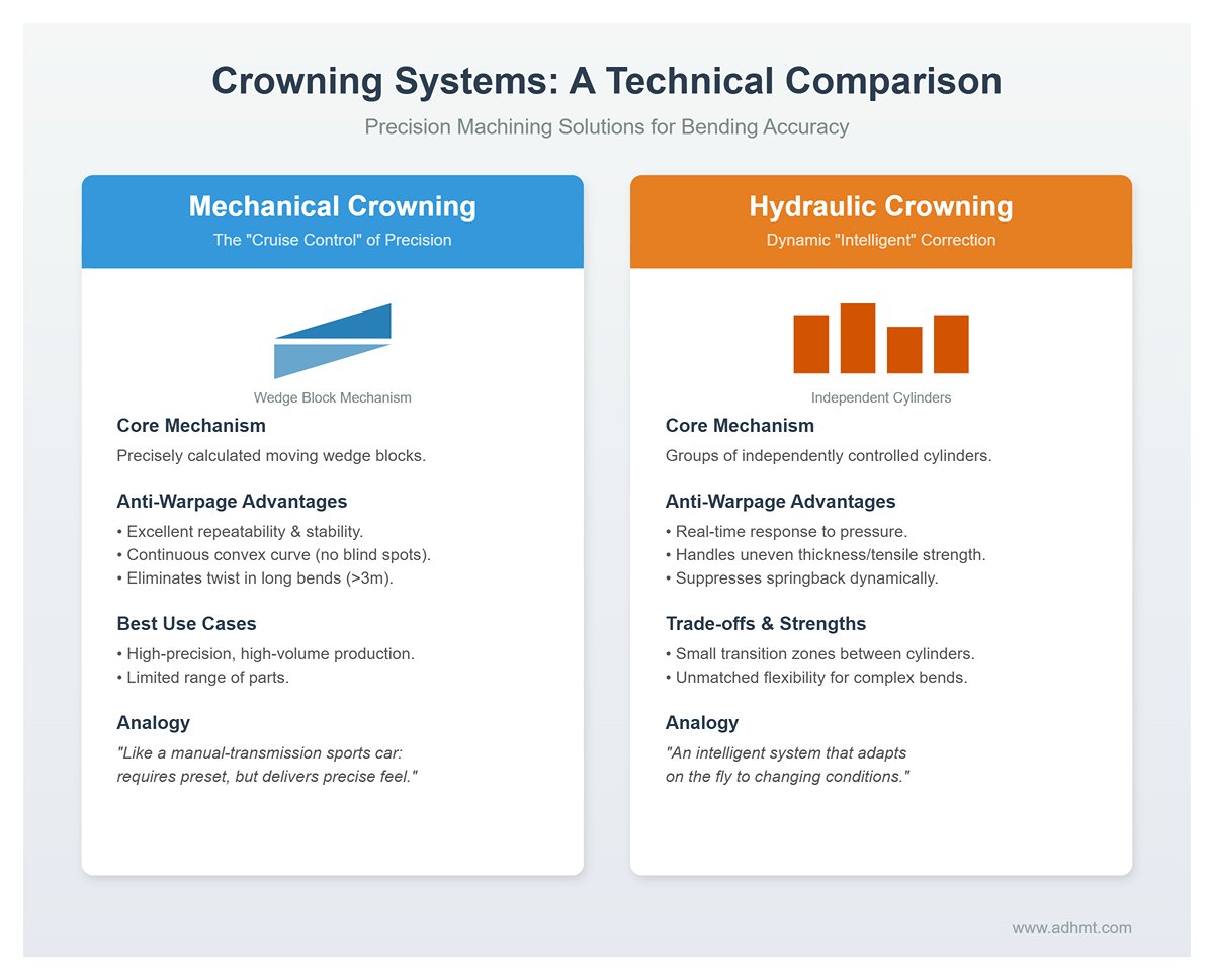
- Mechanical crowning: The “cruise control” of precision Mechanical crowning is regarded as a cornerstone of precision machining. It relies on a set of precisely calculated, relatively moving wedge blocks built into the bed.
- Anti‑warpage advantages: The mechanical positioning of the structure offers excellent repeatability and stability. It can generate a continuous, perfectly controlled convex curve along the full length of the bed, leaving no compensation “blind spots.” For single‑hit, long‑length bends (e.g., over 3 meters), mechanical crowning ensures a consistent angle over the entire part, effectively eliminating twist caused by angle variation.
- Best use cases: High‑precision, high‑volume production of a limited range of parts. It is like a manual‑transmission sports car: it requires presetting, but delivers exceptionally precise “road feel.”
- Hydraulic crowning: Dynamic, “intelligent” correction Hydraulic crowning uses groups of independently controlled hydraulic cylinders under the bed to apply upward force directly.
- Anti‑warpage advantages: Its greatest strength is real‑time response. High‑end systems work with frame‑deformation sensors to adjust the crowning force dynamically in line with actual pressure fluctuations during bending. This is particularly effective for materials with uneven thickness or widely varying tensile strength, as it suppresses springback differences caused by uneven loading in real time.
- Limitations: Because the cylinders are discretely spaced, there can be small transition zones between them where compensation is slightly less uniform. However, for multi‑step bends with complex, changing angles, its flexibility is unmatched.
4.2 Anti‑warpage rules for tooling selection
Tooling is the only interface between the bending process and the material, and its geometry directly determines how stress is distributed. Choosing the wrong tooling is often the “silent killer” behind stress concentration and uncontrolled warpage.
- Rule 1: Rigorously follow the “V-opening = 8 × thickness” golden ratio This is the primary rule for balancing bending force and forming accuracy: the V‑die opening width (V) should be approximately eight times the material thickness (T), i.e., V = 8T.
- Consequences of violation: If the V-opening is too narrow (< 6T), the required tonnage rises dramatically. The punch tip will penetrate deeply into the material surface, producing a very small internal bend radius. This intense, localized plastic deformation causes severe stress concentration, easily mars the surface, and makes springback far more erratic—directly increasing the likelihood of part warpage.
- Material adaptation: This rule should be applied flexibly. For high-strength stainless steel, widen the V-opening to V = 10T to avoid excessive pressure and unwanted deformation. For softer aluminum, tighten it to V = 6T to maintain sharp, well-defined edges.
- Rule 2: Use acute-angle tools to apply an “over-bending” strategy Since springback is a fundamental physical law, the most effective countermeasure is controlled over-bending.
- Key operating principle: If the target angle is 90°, you should never use 90° upper and lower dies. Instead, choose 88°, 86°, or even 30° acute-angle tools and rely on the CNC system’s angle calculation to bend the part, for example, to 88°. The material’s inherent 2° springback will then bring it back to a perfect 90°. This “taking a step back to move forward” approach reserves space for springback and avoids introducing secondary internal stresses from aggressive re-flattening and correction.
- Rule 3: Introduce special tooling to rewrite the physics When the friction characteristics of conventional steel dies become the bottleneck, specialized tools can fundamentally eliminate warping triggers from a tribology (friction science) perspective.
- Rolla-V® rotary insert die: This is a game-changing tool in the war against warpage. In traditional V-die bending, the sheet is “dragged” over the shoulders of the V-opening. The resulting high sliding friction resists material flow and causes tensile deformation. With Rolla-V dies, the shoulders are made of rotating half-cylinder inserts, transforming “sliding friction” into “rolling friction.”
- Core value: This rolling action dramatically reduces bending resistance, preventing distortion of holes located near the bend line and allowing much shorter flange bends. Most importantly, it reduces tangential tensile forces on the sheet surface, significantly lowering the risk of twisting caused by asymmetric stress release.
- Polyurethane (urethane) non-marring dies: For mirror-finish stainless or aluminum sheets, using high-strength urethane pads as the lower die takes advantage of their “fluid-like” enveloping behavior. The bending pressure is distributed evenly across the entire contact area instead of being concentrated along the two V-edges. This uniformly distributed load greatly reduces local stress concentration and is a highly effective way to eliminate the “oil canning effect” and surface indentations.
| Rule | Core Principle | Key Details & Application |
|---|---|---|
| Rule 1: V-opening = 8 × Thickness | Follow the golden ratio ($V = 8T$) to balance bending force and forming accuracy. | • Violation Consequences: If V < 6T, tonnage rises, punch penetrates deeply, and stress concentration occurs, leading to erratic springback and warpage. • Material Adaptation: Widen to V = 10T for high-strength stainless steel; tighten to V = 6T for softer aluminum. |
| Rule 2: Over-bending Strategy | Use acute-angle tools to counteract physical springback (e.g., bend to 88° to achieve a final 90°). | • Operation: Never use 90° dies for a 90° target. Use 88°, 86°, or 30° tools. • Benefit: Allows natural springback without introducing secondary internal stresses from aggressive re-flattening. |
| Rule 3: Special Tooling | Introduce specialized tools to alter friction characteristics (Tribology) and eliminate warping triggers. | • Rolla-V® Rotary Insert Die: Transforms "sliding friction" into "rolling friction" via rotating inserts. Reduces drag, prevents hole distortion, allows shorter flanges, and minimizes twisting. • Polyurethane Dies: Uses "fluid-like" enveloping to distribute pressure evenly. Eliminates "oil canning" and surface indentations on mirror-finish materials. |
V. Strategy Three: Process parameters and programming optimization (Process & Programming)
If high-precision machines and tools are the refined “weapons” in the battle against warpage, then process parameters and programming logic are the “tactics” that direct those weapons. Even the sharpest sword is useless if wielded incorrectly. The core of this strategy is to use software intelligence and logical planning to fully unlock hardware potential and, from the operational side, directly intervene in and cut off the pathways that lead to warping.
5.1 Fine-tuning critical parameters
Modern CNC press brake controllers (such as Delem, Cybelec, etc.) offer a dizzying array of parameter settings. For an average operator, these are just numbers; but for process engineers chasing extreme flatness, three of them hide the “devilish details” that govern warpage and springback. Carefully tuning these often delivers immediate, visible improvements.
- Parameter 1: Bending speed — the art of slowing down
- Control strategy: Within the limits of the required production cycle time, substantially reduce the speed as the punch approaches the bending point.
- Physical rationale: For the material, high-speed bending is a violent “impact.” The resulting high strain rate in a very short time leads to a highly uneven internal stress distribution, like throwing a rock hard into a calm lake and causing turbulent waves. A slow, steady bending process gives the metal lattice enough time to “flow” and reorganize, producing a more uniform internal stress state. This improves angle consistency and reduces unintended deformation.
- Parameter 2: Dwell time — giving the stress a chance to “take a breath”
- Control strategy: When the ram reaches bottom dead center, explicitly set a dwell time of 0.5 to 1 second under pressure.
- Physical rationale: Dwell is not just a pause; it is a micro-level correction process that leverages the material’s creep behavior. Academic studies show that during this brief second under die constraint, the highly stressed lattice undergoes stress relaxation. This “temporary compromise” effectively reduces the elastic energy available for springback when the load is removed. Experimental data indicate that dwell time can contribute up to a 47% reduction in springback amplitude, making it one of the lowest-cost measures to combat warpage.
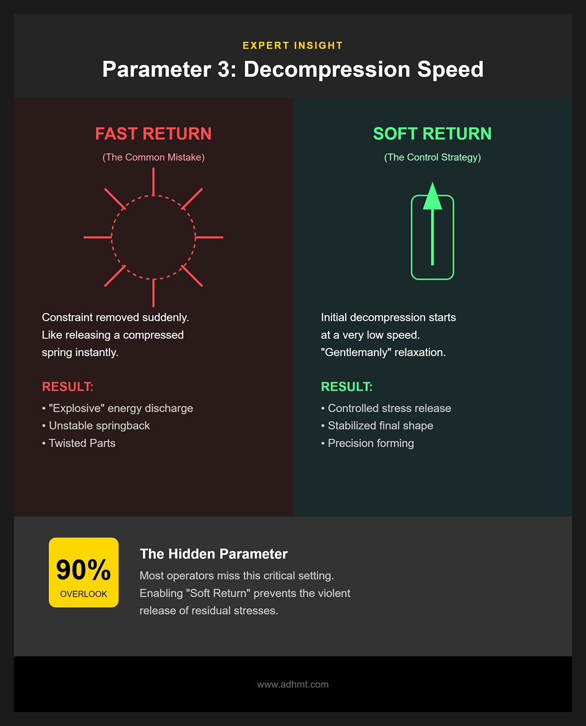
- 💡 Expert insight: Parameter 3: Decompression (return) speed This is a hidden parameter that 90% of operators overlook, yet it is critical for precision forming. It defines the speed at which the upper die moves back up immediately after completing the bend.
- Control strategy: Enable and set “soft return”, meaning the initial decompression should start at a very low speed.
- Physical rationale: If the upper die shoots up at high speed immediately after dwell, it is equivalent to suddenly removing all constraints. The trapped residual stresses then release like a compressed spring that is let go in an instant, “explosively” discharging energy. This violent release causes a large, unstable amount of springback and can twist the part. A slow decompression allows the stresses to relax in a more controlled, “gentlemanly” manner, stabilizing the final shape of the workpiece.
5.2 Bending mode and sequencing logic
The choice of bending method—and the sequence in which multiple bends are performed on a complex part—directly determines how residual stresses accumulate and what final geometric accuracy you achieve.
- Choosing the bending mode: air bending vs. bottoming
- Air bending: Currently the most common method, forming the angle through three-point contact. While highly flexible, it is extremely sensitive to variations in material thickness tolerance and tensile strength. This sensitivity is a major source of angle variation and warpage.
- Bottoming: To achieve ultimate consistency, you need to move to bottoming. In this mode, the punch tip slightly “coins” into the material’s internal radius, and the required tonnage is roughly 2–3 times that of air bending.
- Anti-warping benefits: With this high-pressure coining effect, the material at the bend root is forced into full plastic deformation, effectively “locking in” the angle. This enforced geometric fixation greatly suppresses warpage caused by uneven springback. For mass production of high-precision parts, it is a wise tradeoff: sacrificing press capacity to gain much higher yield and dimensional stability.
- Bend sequence logic: from “guerrilla tactics” to “war-game simulation” Poor bending sequences can cause self-interference of the part and build up cumulative errors.
- Golden rules:
- Inside-first, outside-later: First complete bends on internal features or closed areas, then move to the outer profile. This prevents “trapping” yourself with earlier bends that block later operations.
- Short flanges before long ones: Bend short flanges first to avoid situations where long, already-formed flanges interfere with positioning and handling of shorter edges.
- 💡 Advanced Tool: 3D Simulation Software (Offline Programming) For complex parts, the human brain alone can no longer foresee every potential collision or stress hotspot. Modern manufacturing has to rely on offline programming software (such as AutoPOL, Radbend, etc.). Engineers import the 3D model into a virtual environment, where the software not only calculates the optimal bending sequence automatically, but also highlights all potential collision risks in bright red. This kind of “virtual trial-and-error” completely eliminates scrap caused by incorrect bending order and is an essential tool for controlling warpage in complex structural parts.
- Golden rules:
5.3 Application of Auxiliary Support Systems
When working with large thin sheets or heavy plate, gravity itself becomes a major source of deformation. Relying on manual support is not only unsafe, it also makes it impossible to maintain uniform loading during bending.
- Advanced Assistance: CNC Sheet Followers This is the ultimate physical add‑on for eliminating the “whip effect” and warpage in large thin sheets.
- Working Principle: This is a set of support arms mounted at the front of the press brake and driven by independent servo motors. Their vertical motion path is kept perfectly synchronized with the ram stroke.
- Anti‑warpage mechanism: During bending, the overhanging portion of the sheet generates a large counter‑moment due to gravity, causing unintended tensile deformation in the material near the bend line. The follower system acts like a pair of “invisible giant hands,” continuously and synchronously supporting the lifted part of the sheet, providing stable support at all times. This physically eliminates the reverse bending moment induced by gravity. For large enclosures, doors and other thin‑sheet components, it delivers an immediate reduction in sagging and warpage around the bend line.
- 💡 Cutting Edge: Real‑time Laser Angle Correction (Adaptive Bending) This is the “black technology” that pushes process control to the ultimate closed‑loop level. High‑precision laser emitters and sensors are mounted on both sides of the press brake throat to continuously scan the angle of the sheet during bending.
- Closed‑loop feedback: Instead of blindly following a preset ram depth, the system constantly compares the measured real‑time angle with the target value. If it detects excessive springback or material hardening, the CNC will dynamically and with micrometer‑level resolution correct the ram position within the same stroke.
- Value: This technology effectively neutralizes batch‑to‑batch variation in material thickness, grain direction, and hardness, ensuring every bend is spot‑on. It represents a leap from “experience‑based prediction” to “real‑time correction” and is currently the most advanced method available for achieving bending consistency and eliminating warpage.
VI. Next‑Level Frontiers: Smart Manufacturing and Data‑Driven Control (Industry 4.0)
Material control, hardware upgrades, and process optimization represent the “present tense” of bending technology. Smart manufacturing and data‑driven methods, however, are the “future in progress.” Under the sweeping wave of Industry 4.0, bending shops are undergoing a profound shift from “experience‑driven” to “data‑driven” operations. Solving warpage is no longer about relying on an old master’s “feel” or a single machine’s precision; it is about building an intelligent ecosystem powered by algorithms, sensors, and digital twins. At this level, we are no longer passively “eliminating” warpage, but proactively predicting and “managing” it.
6.1 Closed‑Loop Control Systems
Traditional CNC bending is typically “open‑loop”: the control system drives the ram to a specific position based on preset parameters and assumes the result will be correct. In reality, even small batch‑to‑batch differences in material (such as thickness tolerance or tensile strength variation) can cause angle deviations, leading to uneven springback and warpage. A closed‑loop control system effectively adds “eyes” and a “brain” to the press brake, completing the leap from “blind execution” to “real‑time sensing and correction.”
- Real‑time Angle Measurement: This is the core of closed‑loop control. Using high‑precision laser sensors integrated into the tooling or machine frame (such as LUV systems) or contact probes (such as ACB systems), the machine can monitor the angle changes of the sheet in milliseconds as the ram descends.
- Dynamic Springback Compensation: Instead of waiting until the bend is finished, the system captures the material’s true springback behavior during the bending process itself—especially at the instant of unloading and springback.
- Workflow: Ram moves down → Sensor measures actual angle → System calculates springback → Deviation detected → Ram automatically fine‑tunes the bottoming depth within the same stroke (micrometer‑level correction) → Angle measured again → Perfect angle achieved.
- Anti‑warpage benefit: This mechanism fundamentally eliminates warpage caused by material inconsistency between batches. Even if hardness varies across different regions of the same sheet, the closed‑loop system can apply independent, adaptive compensation for each bend, ensuring consistent final forming accuracy.
6.2 Simulation and Digital Twins (FEA & Digital Twin)
Trial‑and‑error in the physical world is expensive and inefficient. Digital twin technology allows us to rehearse the entire bending process in a virtual environment and eliminate warpage risks as early as the design stage.
- Advanced Use of Finite Element Analysis (FEA): Conventional bending simulation software usually focuses only on geometric interference (collision detection). FEA‑based advanced simulation tools (such as AutoForm, Simufact) go a step further into the domain of material mechanics.
- Predicting Invisible Forces: By inputting the material’s stress‑strain curve, anisotropy parameters, and tool friction coefficients, the software can accurately calculate the residual stress distribution after bending. It can forecast potential “oil‑canning,” springback tendencies, and distortion risks in advance.
- Reverse Compensation Design: A more advanced application is “reverse engineering” for compensation. If the simulation predicts a 1 mm bow‑shaped warpage, the software can guide engineers to pre‑cut a slight counter‑curve at the blanking stage, or automatically generate a flat pattern that includes springback compensation. After physical bending, the result is a straight part.
- Full‑factor Digital Twin: This is far more than just a 3D model of the part; it is a digital mirror of the entire bending cell. It includes the real kinematics of the machine, current tool wear conditions, and even robot gripping paths. Programs validated in the virtual environment can be sent directly to the shop floor for execution, achieving “first‑part‑right” production and eliminating scrap and warpage caused by parameter trial‑and‑error.
6.3 Knowledge‑Base‑Driven Parameter Optimization
The most advanced anti‑warpage strategy is to convert the experience of an entire plant—or even an entire industry—into data and build a continuously evolving “expert system.”
- Cloud‑based Material Database: As the steel supply chain becomes increasingly digital, leading factories are starting to import mill certificate data directly into their MES systems. After the press brake scans the sheet barcode, it automatically reads the yield strength and elongation of that specific batch and uses this information to call up or adapt the bending parameter library. In other words, the machine no longer uses a single parameter set for all “304 stainless,” but performs precision processing tailored to “this particular heat of 304.”
- AI, machine learning, and self-optimization: Every bending operation and every correction made by the closed-loop system is logged and fed back into a central knowledge base. Using machine learning algorithms, the system progressively learns and identifies deformation patterns for specific material grades and tooling combinations.
- Scenario simulation: When the system later encounters a similar combination of thickness, material, and bend length, it will automatically recommend an “optimal” set of parameters—validated by historical data—instead of leaving the operator to rely on intuition. These parameters can include dwell time, decompression speed, and crowning compensation values. This data-driven decision model minimizes quality variation caused by human factors and turns warp control into a standardized, repeatable capability.
💡 Expert insight: the shift from craftsmanship to computing power In the era of Industry 4.0, the ultimate solution to CNC bending deformation is no longer to rely on a single master operator with 20 years of experience, but to build an intelligent closed loop powered by sensors, algorithms, and data. This makes manufacturing processes transparent, predictable, and self-correcting. For manufacturers pursuing extreme precision, embracing data is equivalent to embracing a zero-defect future.
VII. Conclusion
This guide distills warpage control down to a clear, end‑to‑end framework: understand the mechanical causes, manage materials and tooling, refine programming, and finally use data and intelligent systems to keep bends stable and predictable.
With this structure, manufacturers can move from passive troubleshooting to actively engineering bending quality into every part. For a deeper understanding of how a press brake functions within this framework, exploring its mechanical principles can help optimize bending precision.
If you want to apply these ideas on real projects, ADH Machine Tool can support you with equipment selection, process optimization, and smart warpage‑control solutions tailored to your plant. To discuss your current bending issues and explore a customized path to higher consistency and lower rework, feel free to contact us.


