AutoCAD Sheet Metal Design for CNC Press Brake is not just about drawing pretty flat patterns; it is about encoding real-world bending physics, machine limits, and process constraints directly into your CAD decisions so parts form right the first time on the shop floor. Most engineers learn this the hard way: a model that looks perfect on screen turns into cracked bends, distorted holes, and overloaded press brakes once it meets real material and tooling.
This article takes a different path—starting from the gap between virtual lines and physical forming, then building an industrial-grade AutoCAD environment, a five-step standard workflow for flat patterns, a DFM defense checklist, and finally a collaboration model that upgrades the drafter’s role into a true process expert who can speak both geometry and tonnage.
I. Cognitive Reconstruction: Bridging the Gap Between Virtual Lines and Physical Manufacturing
Before drawing your first line in AutoCAD, you need a crucial mental upgrade. In sheet metal design, the two-dimensional lines on your screen are far more than geometric figures—they are mathematical commands that dictate how real materials deform under extreme stress. Most design failures stem not from poor software skills but from the designer’s inability to grasp the transformation from virtual geometry to physical reality.
1.1 Core Pain Points: Why Do Perfect Drawings Lead to Collisions and Scrap?
Many engineers have faced this nightmare moment: an AutoCAD drawing perfectly dimensioned and well annotated, assemblies fitting flawlessly in 3D software—yet once released to the shop floor, operators complain, the press brake alarms, or the tooling gets damaged. This paradox of “perfect drawing, failed part” is essentially a clash between geometric idealism and physical realism.
In AutoCAD’s purely mathematical space, lines have no thickness, right angles are absolute, and the environment is infinite and continuous. In contrast, the physical world of CNC bending is brutally constrained by three dimensions:
- Volume Interference: What appears on-screen as a simple folded edge is, in reality, a sweeping motion of metal around tooling. If a design ignores the bending sequence, the part may crash into the backgauge or upper die clamp during the third bend.
- Material Elongation: Beginners often assume L = A + B. In truth, when metal bends, the outer layer stretches while the inner layer compresses. Ignoring material elongation (in flat pattern calculations) leads to oversized parts that fail to assemble properly.
- The Myth of Sharp Corners: CAD can draw an R0 corner, but in reality, perfect sharp edges don’t exist. Forcing an extremely small inside radius often results in cracking or requires excessive tonnage to bottom-bend—challenging the machine’s physical limits.
In essence, an unmanufacturable drawing is nothing more than an erroneous set of machine instructions.
1.2 Foundational Logic: The DFM (Design for Manufacturing) Mindset
To become a top-tier sheet metal designer, you must cultivate a DFM (Design for Manufacturing) mentality. This means that when you draw, your mind should not only visualize the final product but also simulate every step of its fabrication.
For CNC bending, the DFM mindset rests on three key pillars:
- Tooling Awareness: Your design must align with the available die library. The width of a standard V-groove dictates the minimum flange length. If you design a 5 mm flange but the smallest V-die in the shop requires 8 mm to support the sheet, your design is invalid. Design should adapt to the tooling, not force the tooling to adapt to arbitrary lines.
- Sequence Logic: Bending unfolds over time—what comes first, and what follows? Internal features (like countersinks or louvers) placed too close to bend lines may stretch or distort during forming. Skilled designers predict the bending order while creating the flat pattern and avoid potential deformation zones.
- Springback & Compensation: Metal is elastic. A stainless steel bend intended at 90° may spring back to 92°. While CNC machines can apply angle compensation, designers must allow sufficient tolerance and understand how material properties influence accuracy.
1.3 Mathematical Expression of Core Physical Concepts
In AutoCAD, the complexities of the physical world are distilled into a few key mathematical parameters. Mastering their relationships is the foundation for drawing precise flat patterns.
- Neutral Axis and K-Factor: During bending, the inner side compresses, the outer side stretches, and in between lies the neutral axis — neither elongating nor shortening. The K-Factor is the ratio of the neutral axis position to material thickness (K = t / T). It’s not a fixed constant but a function of material type, thickness, and bend radius. In CAD, this factor directly determines the accuracy of flat pattern development.
- Bend Deduction (BD): This formula connects the 2D flat layout to the final 3D form. L_total = L₁ + L₂ - BD, where L_total is the total unfolded length, and L₁, L₂ are the outside dimensions. BD represents the length you must subtract to account for material stretching.
- Inside Radius (IR): A critical geometric constraint, typically about 1/6 to 1/8 of the V-die width in air bending. Every bend line in CAD corresponds to a specific IR value. If the IR on the drawing doesn’t match the IR produced by the tooling, your flat pattern dimensions will be inaccurate.
Summary: Drawing sheet metal in AutoCAD is essentially a mathematical operation governed by material properties and tooling constraints. The following sections will translate these principles into actionable steps to build a standardized drafting system.
II. Strategic Preparation: Building an Industrial-Grade AutoCAD Environment
Many engineers assume drawing speed depends on how fast they move the mouse. In reality, efficiency and reliability stem from a rock-solid foundational setup. In CNC bending, a DWG file isn’t just a drawing—it’s an uncompiled data package.
If your environment is misconfigured, the subsequent CAM programming phase will be chaotic. This chapter guides you in building a standardized, industrial-grade AutoCAD environment to ensure seamless data flow from design to production.
2.1 CNC-Friendly Layer Management System
In conventional drafting, layers may only separate colors or line weights. In a DFM-oriented setup, however, layers serve as semantic process commands. Advanced CNC shops use automation software (like Radan or Metamation) to read DXF files, where layer names trigger automatic recognition of cut paths, etch marks, and bend lines. Poor layer management can make the machine misinterpret a bend line as a cut path—resulting in scrap.
We must therefore establish a “process-driven” layering system rather than a “visual-driven” one. The following naming convention is recommended:
- G_GEOMETRY (Main Geometry Layer):
G_CUT_OUTER: Outer contour of the part (must be closed; used by laser or punch press to generate the primary cutting path).G_CUT_INNER: Internal holes and slots (must form closed loops).G_ETCH: Surface etching or marking lines (non-cutting, used for identification only).
- M_MFG (Manufacturing Information Layer):
M_BEND_UP: Bend lines indicating upward bends (typically defined as facing up).M_BEND_DOWN: Bend lines indicating downward bends.M_BEND_ID: Bend annotations (e.g., "90° R1").
- D_DATA (Data Support Layer):
D_DIM: Dimension markings (usually filtered out during CAM data import).D_TEXT: Non-geometric textual notes.X_CHECK: Interference check areas or auxiliary reference lines (set to non-printing).
💡 Expert Tip: Save this layer structure as a .dwt template file. When exporting DXF files for production, always use the “Layer Translator” or a cleanup script to remove all irrelevant layers—retain only the geometry and process information that the machines can interpret.
2.2 Precision Control and Environment Configuration
“Looks straight enough” is a dangerous assumption in precision manufacturing. AutoCAD’s default display accuracy often conceals subtle geometric errors, such as a 0.001 mm gap or an angle of 89.99°. These tiny flaws can prevent CAM software from generating closed tool paths or cause misalignment in press brake positioning.
To build a zero-error environment, apply the following configurations:
Absolute Control of Units and Coordinate Systems:
- Units (UNITS): Mixing imperial and metric units is strictly prohibited in mechanical design—set everything to millimeters (mm).
- Display Precision (LUPREC / AUPREC): Set length and angular display precision to the maximum (8 decimal places). This isn’t about achieving nanometer-level manufacturing—it’s for self-verification. If a line shows
100.00002345in the properties bar, you immediately know there was a snap error during drawing. - World Coordinate System (WCS) Origin: Develop the habit of placing a key reference point of the part (such as the lower-left corner or a critical hole center) at the
(0,0,0)origin. This mirrors the “workpiece zero point” logic used in CNC programming and greatly simplifies subsequent data validation.
The Iron Rules of Object Snap (OSNAP):
- Never rely on visual alignment.
- Always enable snapping to “endpoint,” “midpoint,” “center,” and “intersection” when drawing.
- Beware of “Nearest” Snap: This is the main cause of tiny fragment lines and non-orthogonal geometry. Use it only temporarily when absolutely necessary.
2.3 Essential Auxiliary Tool Library
To avoid turning design into repetitive manual labor, you need to build a specialized “arsenal” for sheet metal bending. This not only boosts drawing efficiency by over 50% but also embeds standardized process requirements directly into your drawings.
- Bend Relief Dynamic Block Library: At the root of sheet metal bends, relief slots (notches) are used to prevent tearing or deformation. Don’t manually draw and trim these each time—create dynamic blocks for “round,” “rectangular,” and “tear” reliefs. With parametric controls, you can instantly adjust slot width (e.g., W = T or W = 0.5T) and ensure every notch complies with your company’s process standards.
- Standard Feature Library: Convert common features such as countersinks, press-nut holes, and locating pin holes into standard blocks with attribute text (e.g., "M4 press-nut, pilot hole 5.4 mm"). This prevents errors from memory lapses when entering hole sizes.
- K-Factor and Deduction Table: Although not a built-in CAD tool, this must be linked externally (Xref) or embedded as a table within CAD. You need a shop-tested reference table correlating “V-die width–sheet thickness–deduction value.” If you design based on theoretical calculations while the workshop uses empirical data, dimensional deviations are inevitable. Unified calculation standards are the final piece of the environment configuration puzzle.
Once this industrial-grade environment is established, you’ll have a solid foundation. From here, we move on to the practical stage—creating standardized sheet metal flat patterns.
III. Practical Workflow: The Five-Step Method for Standardized Sheet Metal Unfolding
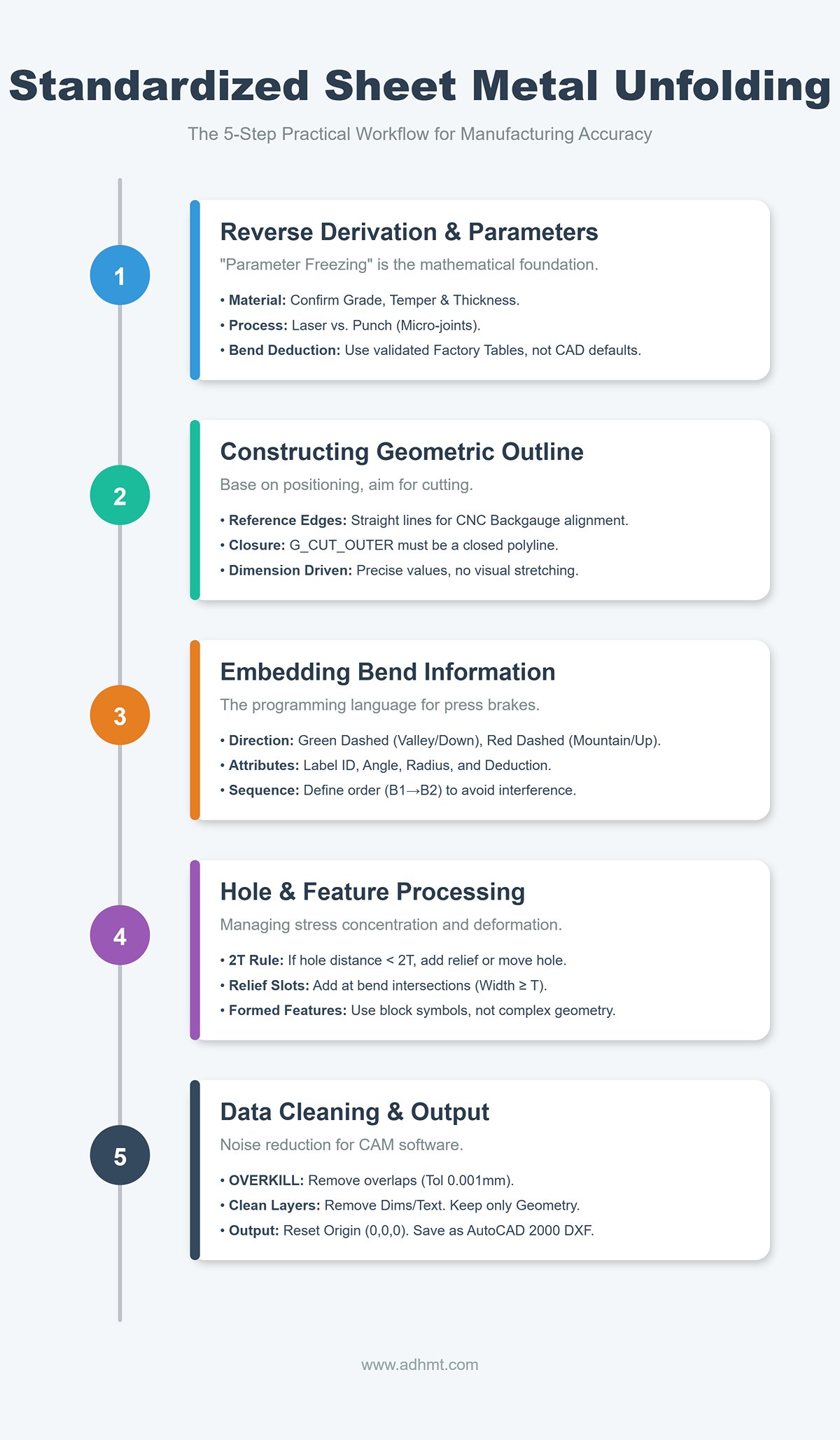
Most drafters mistakenly believe a sheet metal flat pattern is merely a “flattened projection” of a 3D part. In reality, a proper flat pattern is a pre-execution command set for manufacturing. It must embody material properties, stress relief logic, and machine motion paths. We break this process into five standardized steps, each designed to eliminate ambiguity between design and production.
3.1 Step One: Reverse Derivation and Parameter Definition
Before drawing the first line, you must complete “parameter freezing.” Sheet metal unfolding is fundamentally a mathematical process—and its accuracy depends on physical input parameters. If the K-factor or bend deduction is set incorrectly, even a perfectly drawn part will end up as scrap.
- Material Verification: Confirm the material grade (e.g., AL5052-H32 or SUS304) and actual thickness. Note that different temper conditions (soft vs. half-hard) have different springback rates, directly affecting K-factor selection.
- Process Route Definition: Determine whether the manufacturing path is “laser + bending” or “punch + bending.” Punching requires reserving micro-joint positions, while laser cutting is sensitive to heat-affected zones.
- Bend Compensation Table Reference: Never rely on CAD’s default K=0.44 or 0.5 values. Always use the factory’s validated Bend Deduction Table. For example, for 2 mm cold-rolled steel, a V12 die might require a deduction of 3.4 mm, while a V16 die needs 3.8 mm. Before drawing, ensure you know: Which die is actually used on the shop floor?
3.2 Step Two: Constructing the Geometric Outline
The core principle of geometric construction is: Base everything on positioning, aim everything at cutting.
- Establish Reference Edges: On a CNC press brake, the backgauge determines bend line accuracy. Therefore, the flat pattern’s outer contour must include a clear, straight reference edge. Avoid designing complex cutouts or irregular curves along these primary locating edges—they make it impossible for operators to align the part correctly.
- Closure and Layering:
- Outer Contour (G_CUT_OUTER): Must be a fully closed polyline. Even a microscopic gap can prevent the laser cutter from recognizing the path or trigger CAM software errors.
- Inner Contour (G_CUT_INNER): All holes and slots must be placed on independent layers and must also form closed loops.
- Dimension-Driven Geometry: Never adjust shapes by stretching or visual estimation. All geometric modifications must be made by entering precise numerical values or modifying constraints to ensure that the developed length strictly equals L_total = Σ(L_flange) - BD.
3.3 Step 3: Accurate Embedding of Bend Information
This is the defining line between a mere “sketch” and a true “industrial drawing.” Bend lines are not just dashed lines—they serve as the programming language for press brake machines and operators.
- Direction Definition: The bend direction must be clearly distinguished by line type or color—“bend up” vs. “bend down.” The industry convention is: with the front face up, green dashed lines indicate valley bends (downward), and red dashed lines indicate mountain bends (upward). An incorrect bend direction will produce a mirrored part and cause immediate scrap.
- Bend Line Attributes: Next to each bend line, use a non-printing layer to label key parameters, for example:
ID: B1 | 90° | R1.5 | Deduct: 3.4.- Bend Sequence: For complex multi-step bending, anticipate and annotate the recommended order (e.g., B1→B2→B3). This prevents earlier bends from blocking later positioning or causes of self-interference.
- Neutral Axis Verification: Ensure that bend lines are drawn along the neutral layer or offset correctly based on the bend deduction, rather than simply at the intersection of two flanges.
3.4 Step 4: Hole and Feature Processing
This step addresses cases where geometry appears perfect but fails physically, focusing on stress concentration and deformation zones.
- 2T Rule Check: Verify the distance from hole edges to the nearest bend line. If the distance $D < 2T$ (twice the sheet thickness), tensile stress during bending will distort round holes into ellipses. If the hole position cannot be relocated, add a relief cut in the flat pattern to isolate the stress.
- Relief Slot Implementation: At each intersection of a bend line and the outer contour, add relief slots based on material thickness (width ≥ T, depth ≥ T + R). In AutoCAD, sharp 90° bend intersections will tear or compress material in real forming—relief cuts provide necessary space for material flow.
- Formed Feature Substitution: For features like PEM nuts, louvers, or half-shears, only draw the base hole or center mark in the flat layout and reference a standard block symbol. Avoid projecting the complex formed geometry onto the cutting layer.
3.5 Step 5: Data Cleaning and Output
The final step is a data “noise reduction” process to ensure that the file delivered to the CAM software contains only clean geometry.
- OVERKILL Command Cleanup: One of the most underrated AutoCAD commands. Run
OVERKILLwith a tolerance of 0.001 mm to automatically delete overlapping segments and merge collinear lines. This prevents the laser cutter from tracing the same path twice, which could cause burn marks or machine vibration. - Layer Filtering: Before exporting the DXF file, turn off all dimension (D_DIM), annotation (D_TEXT), and title block layers. Retain only geometry layers (G_XX) and bend line layers (M_XX).
- Coordinate Reset: Use the
MOVEcommand to place a key corner of the part—typically the first bend’s reference point—at the world coordinate origin (0,0,0). This ensures that when CNC programmers open the file, the part is already aligned to the origin. - Format Compatibility: Save the file as AutoCAD 2000/2004 DXF. Though dated, this format remains the industry’s most universally compatible standard, readable by nearly all brands of laser and bending software without data loss.
IV. Deep Defense: DFM Manufacturability Review Checklist (Pitfall Guide)
Completing the drawing doesn’t mark the end of the job. Before sending the DXF to the CAM programming team, conduct a rigorous DFM (Design for Manufacturing) review. The goal is to eliminate “expensive physical errors” while they still exist in the “cheap pixel stage.” An unchecked drawing is like a live explosive—it can trigger crashes, damage tooling, or cause mass rework once it hits the shop floor.
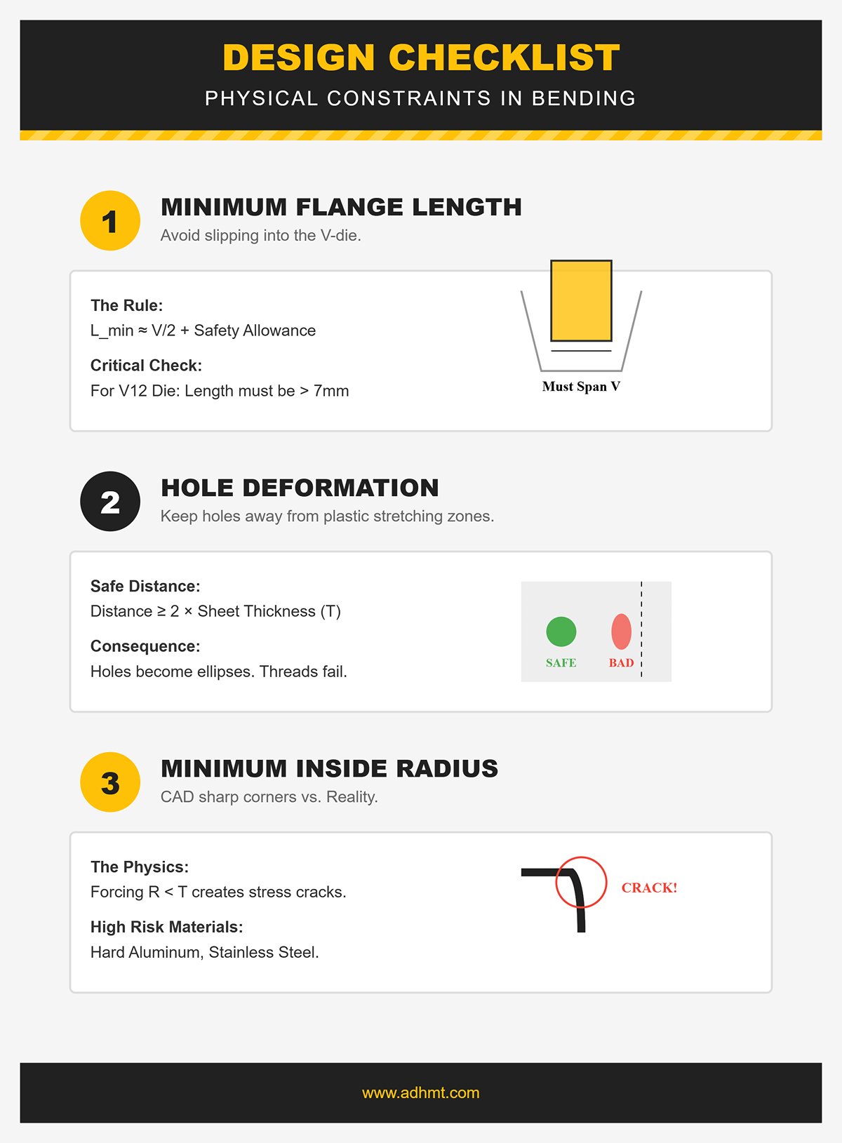
4.1 Geometry and Physical Constraint Review
AutoCAD lets you draw anything, but physical laws and machine capabilities impose strict limits. During review, shift from a “pure geometry mindset” to a “process and physics mindset,” and verify the following constraints one by one:
- Minimum Flange Length: This is one of the most common and dangerous oversights for beginners.
- Physical Logic: During bending, the sheet must span across the V-die opening for proper support. If the flange is too short, the sheet will slip into the V-groove, causing failed bends or even ejection hazards.
- Review Standard: Typically, the minimum flange length $L_{min} \approx V/2 + C$ (C being a safety allowance). For a V12 die, any straight edge shorter than about 7–8 mm is considered high risk.
- Hole Deformation Zone:
- Physical Logic: Material near bend lines undergoes severe plastic stretching. Holes within this zone will distort into ellipses, and threaded holes may fail.
- Review Standard: Check the distance from every hole edge to the nearest bend line. The rule of thumb is D ≥ 2T (T = sheet thickness). If holes must be closer, note “bend first, then ream” or design a relief cut accordingly.
- Minimum Inside Radius:
- Physical Logic: While CAD may show sharp corners (R0), real air bending naturally produces a radius. Forcing a radius smaller than the sheet thickness (R < T) can cause cracking in high-strength materials like hard aluminum or stainless steel.
- Review Standard: Confirm that the specified inside radius (IR) exceeds the material’s minimum bend radius, avoiding fractures caused by overly sharp bends.
4.2 Interference and Collision Detection
Sheet metal bending is a dynamic forming process in which the part moves significantly through space. Many designs look perfect in static view but cause serious physical interference during actual bending.
- Self-Collision:
- Checkpoint: For deep U-, C-, or paperclip-shaped parts, always verify that the bent shape leaves enough clearance for subsequent bending tools. For example, if a deep U-section is narrower than the upper die holder, the press brake simply won’t be able to make that bend.
- Flat Pattern Inspection: When simulating the flat pattern in AutoCAD, carefully check whether adjacent flanges overlap in the unfolded view. AutoCAD’s 2D environment won’t automatically flag such issues—you need to visually confirm that no contour lines intersect.
- Tooling & Machine Collision:
- Checkpoint: During the final bending operation, make sure the already-formed portion of the part won’t collide with the machine’s upper beam or the backgauge fingers.
- Special Countermeasure: For reverse bends or complex Z-shaped bends, evaluate whether a gooseneck punch is required to avoid interference. If your design depends heavily on such special tooling but the shop only has straight punches, the drawing is effectively non-manufacturable.
4.3 Fatal Error Self-Check List (Top 5)
If you only have three minutes for a final review before project delivery, make sure to check this “life-or-death” list. These five mistakes account for roughly 80% of sheet metal fabrication failures.
Tolerance Accumulation Disaster
- Symptom: Every segment of a continuous bend (such as a Z-shape or step form) is dimensioned with a strict ±0.1 mm tolerance.
- Consequence: Bend deviations accumulate. If the first bend is off by 0.1 mm and the second is referenced from the first, the total error can exceed 0.5 mm by the end.
- Correction: Apply tight tolerances only to critical mating dimensions. Mark the rest as reference dimensions to give the shop flexibility to compensate for cumulative errors.
Grain Direction Ignorance
- Symptom: The grain direction of high-strength materials (such as aluminum alloys or spring steel) is not specified during layout or drawing.
- Consequence: When the bend line runs parallel to the rolling grain, the material is prone to brittle cracking along the grain direction.
- Correction: For crack-sensitive materials, clearly mark on the drawing that “bend lines must be perpendicular to the rolling direction.”
Datum Inconsistency
- Symptom: Dimensions on the drawing are referenced from the part edge, while the press brake operator positions using the backgauge (often a hole or another bend line).
- Consequence: When the design datum and process datum differ, the finished part will never match the drawing dimensions.
- Correction: Dimension the drawing as if you were the operator positioning the part on the machine—start from the actual locating edge used on the brake.
Impossible Bend Sequence
- Symptom: A fully enclosed box is designed with all four edges bent inward, leaving minimal internal space.
- Consequence: After the final bend, the part traps the die inside. The only way to remove it is to damage the part or dismantle the tooling.
- Correction: Check for disassembly clearance in closed structures. If necessary, split the part into two pieces and join them by welding.
Missing Bend Reliefs
- Symptom: At the intersection of two adjacent perpendicular bend edges, the drawing shows a sharp corner with no relief.
- Consequence: The metal tears severely at that junction, forming sharp burrs and uncontrolled bulges that compromise assembly quality.
- Correction: Always add a round or rectangular relief notch at the root where the bend line meets the contour line.
V. Delivery and Collaboration: Bridging the “Last Mile” from Design to Shop Floor
When you finish the final line in AutoCAD and complete your DFM review, it may feel like your job is done. In manufacturing reality, however, that’s only the first baton pass in a relay race. A beautiful drawing that never leaves your computer is worthless—its value is realized only when it’s accurately transferred to the shop floor and transformed into a physical part within tolerance.
Many shop-floor failures—using the wrong revision, misreading annotations, or scrapping entire batches due to misunderstood process intent—don’t stem from poor design skills but from broken delivery and collaboration systems. This chapter shows you how to build a professional-grade data delivery structure and an efficient feedback loop.
5.1 The Perfect Delivery Data Package
In the era of Industry 4.0, simply sending a DXF file is irresponsible. A professional designer delivers a complete “Single Source of Truth” package, ensuring that purchasing, laser cutting, bending, and quality teams all work from the same logic. A standard CNC sheet metal delivery package should include three categories of files:
Machine-Readable Geometry (The “Hot” Data)
- Cleaned DXF/DWG: This is the direct input for laser cutters and punch presses—the machine’s “feedstock.” It must include only layers like
G_CUTandM_BEND, with all dimensions, borders, and text removed. The filename should include version and material information, for example:P1023-01_RevB_SUS304_2mm.dxf. - 3D Model (STEP/IGES): Even though this guide focuses on AutoCAD, providing a neutral 3D file format is essential. Press brake operators can import the model into CAM software (such as BendSim) to verify the flat pattern and simulate the bending sequence—your last firewall against incorrect unfoldings.
Human-Readable Engineering Drawings (The “Cold” Data)
- PDF Production Drawing: DXF files contain geometry only, no tolerances. The PDF must clearly specify:
- Critical-to-Quality (CTQ) Dimensions: Identify which dimensions are critical for assembly (e.g., ±0.1 mm) and which follow general tolerances.
- Forming Orientation: Clearly mark the “front view” or “bending direction view” to prevent operators from bending the part in reverse.
- Special Process Notes: Such as “deburr only, no chamfer,” “no press marks allowed on bends,” or “grain direction required.”
Structured BOM and Process List
- Avoid burying material information in a corner of the drawing. Provide a separate BOM that clearly lists part number, revision, material grade, thickness, surface finish (e.g., powder coating, anodizing), and quantity. This prevents purchasing the wrong material or the warehouse issuing the wrong sheet stock.
5.2 Communication and Feedback Mechanisms
“Over-the-wall engineering”—where designers simply toss drawings over to the shop floor and wash their hands of it—is a serious pitfall for manufacturing organizations. You need to establish a two-way communication channel that transforms the shop’s so-called “tribal knowledge” into valuable design assets.
- Pre-release Review: For complex or high-volume orders, invite the bending supervisor to spend ten minutes reviewing the drawings before final release. They can often spot issues instantly—like “this punch isn’t long enough” or “this bend will hit the backgauge.” That brief ten-minute investment can prevent tooling losses worth tens of thousands of yuan.
- Red-line Drawing System: Encourage and standardize shop-floor feedback on drawings. If, during production, an operator finds that the flat pattern dimension is off (for example, the deduction should be 3.5 mm instead of 3.4 mm), they should mark the correction directly on the drawing in red ink, sign, and date it before returning it to the design department. The designer must then update the original file through an official Engineering Change Order (ECO), rather than relying on a verbal reminder for “next time.”
- Respect On-site Expertise: When an operator complains that “this flange is too short to position properly,” resist the urge to argue that it’s theoretically fine. Pain points on the shop floor often expose blind spots in the design. Go to the machine, watch how the operator works—you might find that adding a simple 5 mm scrap tab in the waste area could double their efficiency.
5.3 The Path Forward: From Drafter to Process Expert
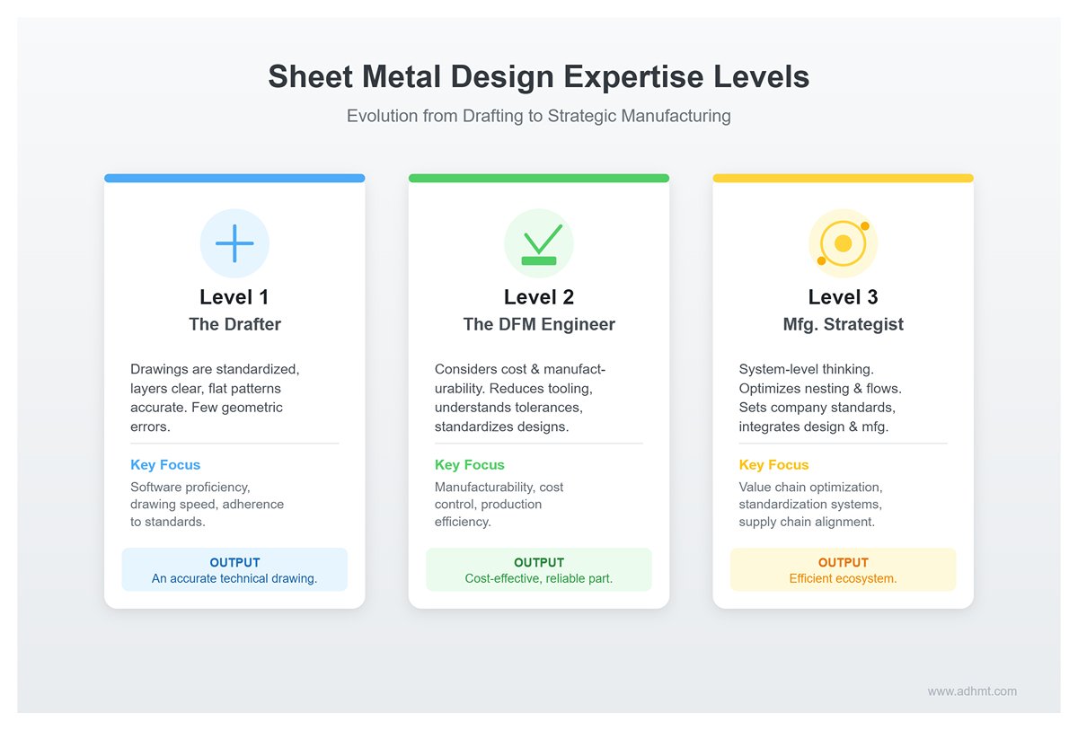
Once you’ve mastered all the technical details of AutoCAD sheet metal design, your career will naturally begin to branch out. In this field, drawing lines is just the foundation—your understanding of manufacturing logic determines how far you can go.
| Level / Title | Traits | Focus | Deliverable |
|---|---|---|---|
| Level 1: The Drafter | Drawings are standardized and organized, layers are clear, and flat patterns are accurate, with few basic geometric errors. | Proficiency in software operation, drawing speed, and adherence to standards. | An accurate technical drawing. |
| Level 2: The DFM Engineer | Considers cost and manufacturability during the design process. Knows how to reduce the number of bending tools by adjusting the structure, understands which tolerance requirements drive up costs, and leverages shared tooling to standardize designs. | Manufacturability, cost control, and production efficiency. | A part that’s easy to produce, cost-effective, and reliable in use. |
| Level 3: The Manufacturing Strategist | Thinks beyond individual parts to the system level. Understands how sheet nesting affects material utilization and how bending operations can become production bottlenecks. Can establish company-wide sheet metal design standards and drive deep integration between design and manufacturing. | Optimizing the entire value chain, building standardization systems, and aligning with the supply chain. | A seamlessly efficient production and design ecosystem. |
From learning to draw a simple bend line, to understanding the physical principles of metal deformation, and ultimately mastering the entire delivery system—this is a challenging yet deeply rewarding journey. May this guide serve as your launching point toward becoming a top-tier sheet metal design expert. Now, you’re ready to hit “Save” and confidently send your data out to the world.
VI. Conclusion
By rethinking tolerances and deformation (DFM), we move beyond CAD perfection to anticipate real-world springback. By adopting an industrial drafting environment and a standardized five-step workflow, we turn experience into replicable assets, ensuring flat patterns withstand the shop floor.
Through deep manufacturability reviews (Checklists) and bridging the design-to-manufacturing gap, we transform from line drawers into "manufacturing architects" who control cost and yield.
True industrial beauty isn’t flashy drawings—it’s silent precision in laser cutting and bending, delivering robust products with minimal scrap. When every K-Factor is refined like art, you deliver a mature solution, not just a DWG. To fully understand how bending precision affects your manufacturing process, explore what a press brake can do in achieving consistent results.
Stop letting perfect lines stay on screen. If you need to optimize your process or find bending equipment that matches your precision, ADH Machine Tool is the answer. You can also contact us directly to discuss customized solutions for your production needs.


