How to Stop Press Brake Operators from Bending Parts Backwards is not about blaming workers; it is about fixing a broken system. A single reverse bend destroys material integrity, disrupts production flow, and drains profit far beyond the cost of scrap metal.
Instead of relying on "paying attention," this guide introduces a 4D Zero-Error System—combining physical Poka-yoke, standardized "Burr Rules," and digital twin technology—to transform your shop floor from a game of chance into a fortress of precision.
I. Deep Diagnosis: Why “Reverse Bending” Is the Most Stubborn Profit Killer on the Shop Floor
1.1 Redefining “Reverse Bending” (The Anatomy of Error)
Don’t dismiss a “wrong bend” as a simple slip of the hand. From the dual perspectives of lean manufacturing and economics, it represents an exponential eruption of sunk cost.
- Irreversibility of Material: Sheet metal bending is a form of plastic deformation. Once bent in the wrong direction, the internal lattice structure of the material undergoes irreversible change, and microcracks form along the bend line. Even if an operator tries to “bend it back,” the fatigue strength in that area typically drops by more than 50%. For precision components subject to structural stress, that means scrapping the part—no room for compromise.
- The Orphan Part Effect: This is the invisible black hole that devours profits. If one piece out of a 100-part batch is scrapped due to a wrong bend, you lose far more than 1% of material cost. To replace that single “orphan part,” the operator must interrupt the laser cutter’s optimized nesting schedule, reload the program, locate leftover material, and produce the part separately. The hidden management and downtime costs of this one-off rework are often 10 to 50 times the cost of producing the original part.
1.2 Root Cause Analysis: The Disconnect Between Vision and Cognition
If your workshop’s solution is still to blame operators for “not paying attention,” you’ll never eliminate this issue. The essence of reverse bending lies in the enormous cognitive friction between two-dimensional drawings and three-dimensional reality.
- The Projection Ghost: The lack of standardization in engineering drawing conventions is a key source of confusion. Is the drawing based on first-angle projection (common in Europe and Asia) or third-angle projection (common in the U.S.)? This determines whether the “bottom” of a view represents the front or the back of the physical part. If the title block isn’t checked—or is incomplete—the brain fills in the blanks based on habit. That subconscious assumption is the main culprit behind reversed orientation errors.
- Burr Side Blindness: After laser cutting or CNC punching, sheet metal naturally has a “shiny side” and a “burr side.” This is the operator’s most intuitive physical reference. Yet most drawings fail to specify “View from Burr Side” or “Burr Up/Down.” When the operator flips the part in hand, they’re effectively performing a spatial guessing game with no physical anchor.
- Linetype Ambiguity: In flat pattern drawings, many DXF files exported from design software have a critical flaw—all bend lines appear as solid lines. In industrial practice, the rule is ironclad: solid = bend up; dashed = bend down. If the design fails to distinguish line types, or the printer can’t clearly show the difference, the operator must mentally simulate the folding process. After repeating this hundreds of times a day, cognitive overload inevitably leads to mistakes.
1.3 Debunking the Three Myths of Traditional Management
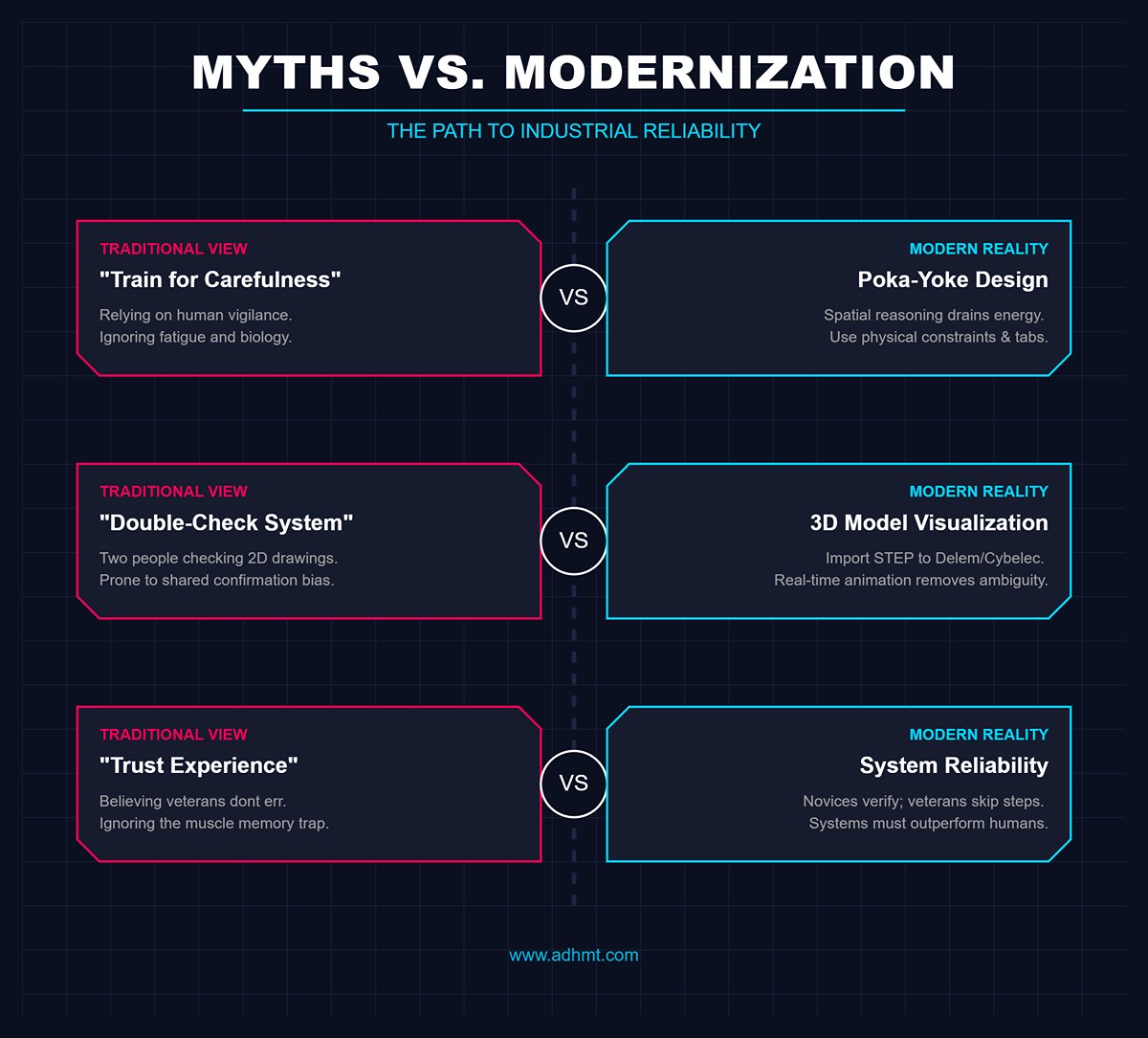
- Myth 1: “Just train workers to be more careful.”
- Reality: Spatial reasoning (mental rotation) is an extremely energy-intensive cognitive process. Psychological research shows that as work hours increase and fatigue sets in, spatial rotation ability drops sharply. Relying on “carefulness” is fighting human biology. The solution is poka-yoke—error-proof design. For example, add asymmetrical tabs at part edges to prevent incorrect placement, or etch bend line names directly on the material during laser cutting. Replace mental judgment with physical constraints.
- Myth 2: “Implement a double-check system before machine setup.”
- Reality: When faced with ambiguous 2D drawings, two people often share the same confirmation bias. Without changing the underlying information source, they’re likely to agree on the same wrong interpretation. A more effective approach is technological—import 3D STEP models into modern CNC systems such as Delem or Cybelec, allowing operators to see real-time folding animations. This turns a “reading comprehension test” into a simple “follow-the-image” task.
- Myth 3: “Experienced operators don’t make mistakes.”
- Reality: Quite the opposite. Statistics show that veterans are more prone to the muscle memory trap. Novices, unsure of themselves, double-check drawings repeatedly. Experienced operators, relying on habit, may skip verification when a part looks similar to a familiar one—even if its bend direction is reversed. System reliability must surpass individual experience. That’s the foundation of true industrialization.
II. Top-Level Design: Building the “4D Zero-Error Defense System”
2.1 System Architecture Overview
The ultimate solution to reverse bending lies in establishing a layered “funnel” defense mechanism. The core idea of the 4D Zero-Error Defense System is to move quality control points far upstream—preventing errors from happening rather than correcting them afterward. By integrating physical, visual, digital, and sensory dimensions, mistakes become virtually impossible.
| Dimension | Strategy Title | Core Focus | Key Implementation | Outcome |
|---|---|---|---|---|
| Dimension 1 | Physical Interlock | Embedding Foolproof Design | Introduce deliberate asymmetry in geometry; add anti-reversal features like tabs or notches on non-mating edges. | Creates physical interference that makes incorrect placement impossible; most cost-effective defense. |
| Dimension 2 | Visual Coercion | Process Documentation & Marking | Replace text-only instructions with 3D simulation screenshots; laser-etch bend lines and direction arrows directly on parts. | Eliminates guesswork by letting the part "speak for itself" via visual markers. |
| Dimension 3 | Digital Twin Interception | Real-Time Equipment Navigation | Utilize 3D CNC systems (e.g., Delem DA-60) for office-side CAM programming and follow 3D animated guidance on the shop floor. | Eliminates ~90% of cognitive errors caused by limited spatial reasoning. |
| Dimension 4 | Light Curtain & Sensor Feedback | Intelligent Hardware Intervention | Deploy sensors (e.g., Lazer Safe IRIS) to monitor workpiece profiles and trigger a "hard brake" if position deviates from the 3D model. | Serves as the final line of defense to stop errors before they become costly scrap. |
- Dimension 1: Physical Interlock – Embedding Foolproof Design This is the most cost-effective yet decisive line of defense. During part geometry design, introduce deliberate asymmetry. If a part is geometrically symmetrical but its bending direction isn’t, that’s a design flaw. Add small anti-reversal features—like a tab or notch—on non-mating edges. The logic is simple: if the part is placed incorrectly, the physical interference makes it impossible to fit into the backgauge or creates an obvious visual mismatch.
- Dimension 2: Visual Coercion – “What You See Is What You Bend” on the Process Side Eliminate text-only work instructions. At this level, process documentation must include 3D bending simulation screenshots with clear directional markers such as “Burr Side Up” or “Burr Side Down.” Take it further by using engraving functions during laser cutting or stamping to etch bend line names and direction arrows directly on the non-visible surface. Let the part “speak for itself,” removing any chance for guesswork.
- Dimension 3: Digital Twin Interception — Real-Time Equipment Navigation This marks the turning point in modern sheet metal processing. By leveraging CNC systems such as the Delem DA-60 series or Cybelec ModEva, which feature 3D visualization, complete 3D programming—including tools, workpieces, and backgauges—is performed at the office (CAM) stage. Once the program is transmitted, operators no longer deal with dull X/Y coordinate data but follow 3D animated guidance that mirrors real-world movements. The hand moves exactly as the screen shows. This “digital twin” technology eliminates nearly 90% of cognitive errors caused by limited spatial reasoning.
- Dimension 4: Light Curtain and Sensor Feedback — The Final Line of Defense For high-value or structurally critical parts, intelligent hardware intervention becomes essential. Systems such as Lazer Safe IRIS with integrated cameras or real-time angle measurement devices continuously monitor the workpiece profile. If the operator places the sheet in a position that deviates from the programmed 3D model, the sensors instantly detect the anomaly and the machine refuses to proceed with the bending command. This “hard brake” ensures that even if all previous layers of defense fail, errors are stopped before becoming costly scrap.
2.2 Core Logic: A Strategic Shift from Human Defense to Technical Defense
The biggest flaw in traditional management is the attempt to fight probability through human responsibility. Fatigue, emotions, and cognitive bias are inherent limitations of human physiology. The four-dimensional system accepts human unreliability and instead places full trust in physical constraints and digital logic. This represents a strategic transition from Human Defense to Technical Defense.
- Redefining “Positive De-skilling”: Here, de-skilling is not a derogatory term but an inevitable step in industrial evolution. The complex spatial judgment required to determine bending direction should be shifted from the operator’s brain to the CAD engineer and CAM software algorithms. On-site operators become executors rather than decision-makers—following on-screen guidance as if playing a game. This approach not only drives error rates to near zero but also reduces new employee training cycles from months to mere days.
- Solving the “Do It Right the First Time” Cost Paradox: Many managers question whether engraving every part or performing 3D offline programming is too time-consuming. This mindset is short-sighted. The economics of the blink moment: If a programmer spends an extra two minutes in the office designing foolproof features, the workshop saves twenty minutes of downtime for verification and avoids thousands in potential scrap losses. Errors in the virtual world (software simulation collisions) cost nothing, while errors in the physical world are expensive. The high ROI of technical defense lies in converting costly physical trial-and-error into low-cost digital computation.
Once this system is in place, your workshop will no longer depend on the mood or state of a veteran operator—it will operate as a precise, self-correcting modern machine. This is the fundamental difference between “craft-based processing” and “industrial manufacturing.”
III. Dimensions One and Two: Hardcore Error-Proofing Technologies (Design and Hardware Layers)
In traditional workshop management, we tend to correct mistakes by enforcing discipline; in world-class lean manufacturing, we eliminate mistakes by redesigning the physical environment. Dimensions One and Two form the foundation of this defense system.
Their shared logic is simple: instead of relying on the operator’s subjective judgment, use geometric features and hardware mechanisms to make “doing it right” the only physically possible option.
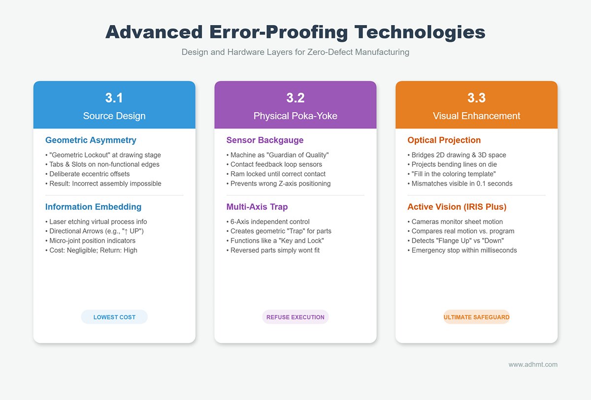
3.1 Source Design: Eliminating Errors at the Drawing Stage
Core Principle: If a part is geometrically symmetrical but its bending logic is asymmetrical, that’s a design failure.
Design engineers must recognize that they are not only designing product functionality but also manufacturing feasibility (DFM). Introducing “geometric lockout” mechanisms at the drawing stage is the lowest-cost, highest-return error-proofing measure.
- Geometric Asymmetry Locking:
- Foolproof Tabs & Slots: For elongated or rectangular parts that are easily placed in the wrong orientation, add a small tab (e.g., 3mm x 2mm) or asymmetric notch along a non-functional edge. During programming, use this tab as the backgauge reference point. If the operator attempts to insert the part in reverse, the tab will fail to contact the gauge or cause a physical clash with the die—making incorrect positioning physically impossible.
- Deliberate Eccentric Design: When a part includes an array of holes, intentionally offset the centerline (e.g., by 2mm). If the operator bends the part incorrectly, the holes will never align during assembly. This design shifts error feedback from the “customer complaint” stage to the “next process” stage—harsh but highly effective.
- Physical Information Embedding:
- Laser Etching Navigation: Use the laser cutter’s etching function to embed virtual process information directly into the sheet metal.
- Directional Arrows: Etch markings such as “↑ UP” or bend line names onto the sheet surface.
- Micro-Joint Indicators: Use the position of micro-joints (e.g., all parts featuring residual joints at the lower-left corner) to indicate orientation.
- Cost Analysis: This adds only a few seconds to the laser cutting cycle—virtually negligible in cost—yet gives each part the ability to “speak for itself,” eliminating the era of operators guessing orientations.
- Laser Etching Navigation: Use the laser cutter’s etching function to embed virtual process information directly into the sheet metal.
3.2 Physical Poka-Yoke Devices
Core Principle: When design cannot be altered, machines must possess the intelligence to “refuse execution.”
Modern CNC press brakes should serve not just as execution tools but as guardians of quality. Through hardware upgrades, error-proofing logic can be embedded directly into the machine’s control system.
- Sensor-Integrated Backgauge:
- Contact Feedback Loop: High-end press brakes (e.g., Trumpf, Amada) feature backgauges with ultra-sensitive contact sensors. The system only gives a green light and allows the ram to descend when the workpiece simultaneously and correctly contacts all predefined gauge points. If the operator places the part incorrectly—touching only one point or the wrong Z-axis position—the machine remains locked.
- Multi-Axis Trap Positioning (6-Axis Trap): Leveraging the independent control of six axes—X1/X2, R1/R2, and Z1/Z2—the system can create “trap-style” backgauge finger positions tailored for irregularly shaped parts. Instead of aligning all fingers in a straight line, they form a specific geometric array that only accommodates a part placed in its correct orientation. It works like a key and lock—if the part is reversed, it simply won’t “fit” into the slot.
3.3 Visual Enhancement System
Core Concept: Use augmented reality (AR) to bridge the cognitive gap between two-dimensional drawings and three-dimensional space.
Since the human brain struggles with spatial rotation, technology should provide the answer directly—by literally drawing it in front of the operator’s eyes.
- Optical Projection Assistance:
- This is the industrial version of “what you see is what you get.” High-precision projectors cast bending lines, die positions, part outlines, and even placement directions onto the lower die surface. Operators don’t need to look up at screens; they simply align the sheet metal’s shadow with the light projection—like filling in a coloring template. If the part is reversed, the mismatch between the real contour and the projected outline is immediately visible, triggering an instinctive correction within 0.1 seconds.
- Active Vision Monitoring:
- Advanced light curtain systems such as Lazer Safe IRIS Plus act not only as safety devices but also as process monitors. The system’s cameras capture the sheet’s motion in real time during bending. If the program specifies a “Flange Up” bend but the camera detects a “Flange Down” movement, it will trigger an emergency stop and error alert within milliseconds. This serves as the ultimate safeguard—ensuring that even if all previous fail-safes fail, incorrect operations can never result in defective parts.
Through these three layers of robust technological intervention, we transform error prevention from a soft management concept based on “responsibility” into a hard constraint governed by “physical laws” and “digital logic.” This forms the material foundation for achieving zero defects.
IV. Dimension Three: Process Standardization and Workflow Control (Execution Level)
If design-level mistake-proofing is the “genetic modification” and hardware-level control is the “physical constraint,” then process standardization is the shop floor’s “muscle memory.” At the execution level, we must recognize that disorder breeds mistakes.
When operators must search through a pile of disorganized parts or struggle to interpret unclear written instructions, their cognitive bandwidth is consumed by irrelevant tasks—creating fertile ground for errors. This chapter establishes a surgical-level standard workflow that turns “casual operation” into “precise execution.”
4.1 The Golden Rule: The Burr Rule

In chaotic workshops, the root cause of reversed bends often lies in a lack of unified reference standards. Is the drawing in first-angle or third-angle projection? Does “front side” mean the painted surface or the unpainted one? To eliminate such ambiguity, we must establish a factory-wide constitutional rule—the Burr Rule.
- Establishing a Physical Anchor Point: Every sheet cut by laser or CNC punch naturally has a physical characteristic—the Burr Side. It is the only inherent, unchangeable, and visually independent physical reference on the part.
- Touch Over Sight: Human vision is easily deceived by lighting or fatigue, but touch remains precise and consistent. The rule: “Burr Side = Inside Radius” (or defined as the outside depending on the process).
- Full Process Integration:
- Design Phase: All engineering drawings must clearly indicate the reference state in the title block, such as “View from Burr Side.”
- Operation Phase: The operator’s first action upon picking up the sheet is not to squint at the drawing but to feel the edge. Once the fingertips detect the rough burr texture, the brain instantly triggers muscle memory to orient the part correctly (for example, burr side facing down) without requiring complex spatial visualization.
The brilliance of this rule lies in reducing high-level spatial cognition to a binary tactile confirmation—rough or smooth. When “feeling the sheet” becomes as instinctive as breathing, orientation errors are eliminated at their source.
4.2 Militarized Preparation and Loading Management
Don’t expect operators to act as both “porters” and “inspectors” in front of the machine. If they must rummage through chaotic trays or distinguish part orientations, each search becomes a moment of distraction—a potential trigger for reversed bends.
- Kitting & Uniform Orientation:
- Implement a “pre-sorting” mechanism. Before entering the bending station, all parts must be pre-kitted by logistics personnel.
- Enforce a strict “same-direction stacking” rule. Every sheet on a pallet must maintain identical physical orientation (e.g., all smooth sides facing up, all cut edges facing outward). This ensures that the operator’s wrist motion when picking up the first or hundredth sheet is identical—eliminating any need for directional thinking or adjustment.
- 5S Layout and Physical Segregation:
- Shadow Board for Dies: Die carts should be organized according to each machine’s configuration using “shadow management.” Each die has a designated, outline-marked position to prevent selection errors that could cause parameter mismatches and lead operators to misjudge part orientation.
- Left-Right Segregation for Error Prevention: Mark clear zones on the workstation using tape. Define “Left In, Right Out”—the left side always holds “parts to be processed,” while the right side holds “finished parts.” This physical separation drastically reduces the risk of mistakenly reloading a bent semi-finished part as a new blank, which could cause catastrophic reverse double bending.
4.3 Zero-Defect SOP Development Techniques
A traditional, text-heavy Word-based work instruction (SOP) usually ends up buried in a drawer. An effective mistake-proof SOP should resemble a Lego manual—visual, intuitive, and action-oriented.
- The Three-Second Rule: Operators have minimal time to read SOPs. If they can’t grasp the key message within three seconds, they’ll stop reading and rely on intuition. Therefore, SOPs must minimize text and maximize visual representation.
- Embedding Core Error-Proofing Elements:
- 3D Placement Simulation: Each SOP must include a 3D image showing the part positioned on the lower die, with the current bend line highlighted in red.
- Symbolic Instructions: Replace text with clear icons—for example, a magnified burr symbol paired with a downward arrow to indicate “burr side down,” or a backgauge icon to indicate “align with backgauge.”
- Asymmetric Feature Close-Up: When the correct orientation of a part depends on a small notch or tab, the SOP must include a zoomed-in close-up image with a red circle highlighting the feature, accompanied by a clear warning symbol.
- Digital Extension: Print a QR code on the paper-based SOP. For highly complex or irregular parts, operators can scan the code to access a rotatable 3D model on a tablet for better visualization.
By standardizing perception with the “Burr Law,” regulating physical actions through “military-style loading,” and locking in visual focus via the “LEGO-style SOP,” we create a tightly integrated cognitive loop around each operator—making it increasingly difficult for errors to occur in the first place.
V. Dimension Four: Cognitive Upgrade and Management Loop (People and Culture Layer)
If the first three dimensions build an iron wall against mistakes, the fourth dimension provides its soul. Even the most advanced poka-yoke fixtures and 3D visualization systems will fail if operators lose focus or if management implicitly encourages concealment.
We must elevate operators from being mere extensions of machines to becoming true “industrial athletes,” supported by a cultural immune system where errors have nowhere to hide.
5.1 Targeted Skills Training: From Apprenticeship to Professionalization
The traditional “master-and-apprentice” model often passes on not only experience but also bad habits. In a zero-defect system, bending is no longer a craft guided by intuition—it becomes a precision process grounded in scientific cognition. We need to reconstruct workforce capabilities accordingly.
1. Spatial Rotation Drills: The core cognitive skill for bending operators is not physical strength but mental rotation—the ability to visualize how a 2D drawing transforms into a 3D object. Much like a pilot’s spatial awareness, this ability can be systematically developed through training.
- Cognitive Warm-Up: Replace unproductive morning speeches with “cognitive activation.” For the first five minutes of each shift, use simple spatial logic test software (similar to visual rotation puzzles found in IQ tests) to stimulate the brain’s parietal region.
- Blind Sensory Drills: Building on the “Burr Law,” conduct hands-on exercises akin to “blindfolded recognition.” Operators close their eyes and identify the burr side and anti-error notch purely by touch, then position the sheet correctly. This training builds a direct neural pathway between tactile cues and muscle memory, bypassing potentially deceptive visual perception, turning correct operation into instinct.
2. Skills Matrix Certification: Not everyone is suited to process every type of part. Implementing a strict tiered authorization system is key to minimizing risk:
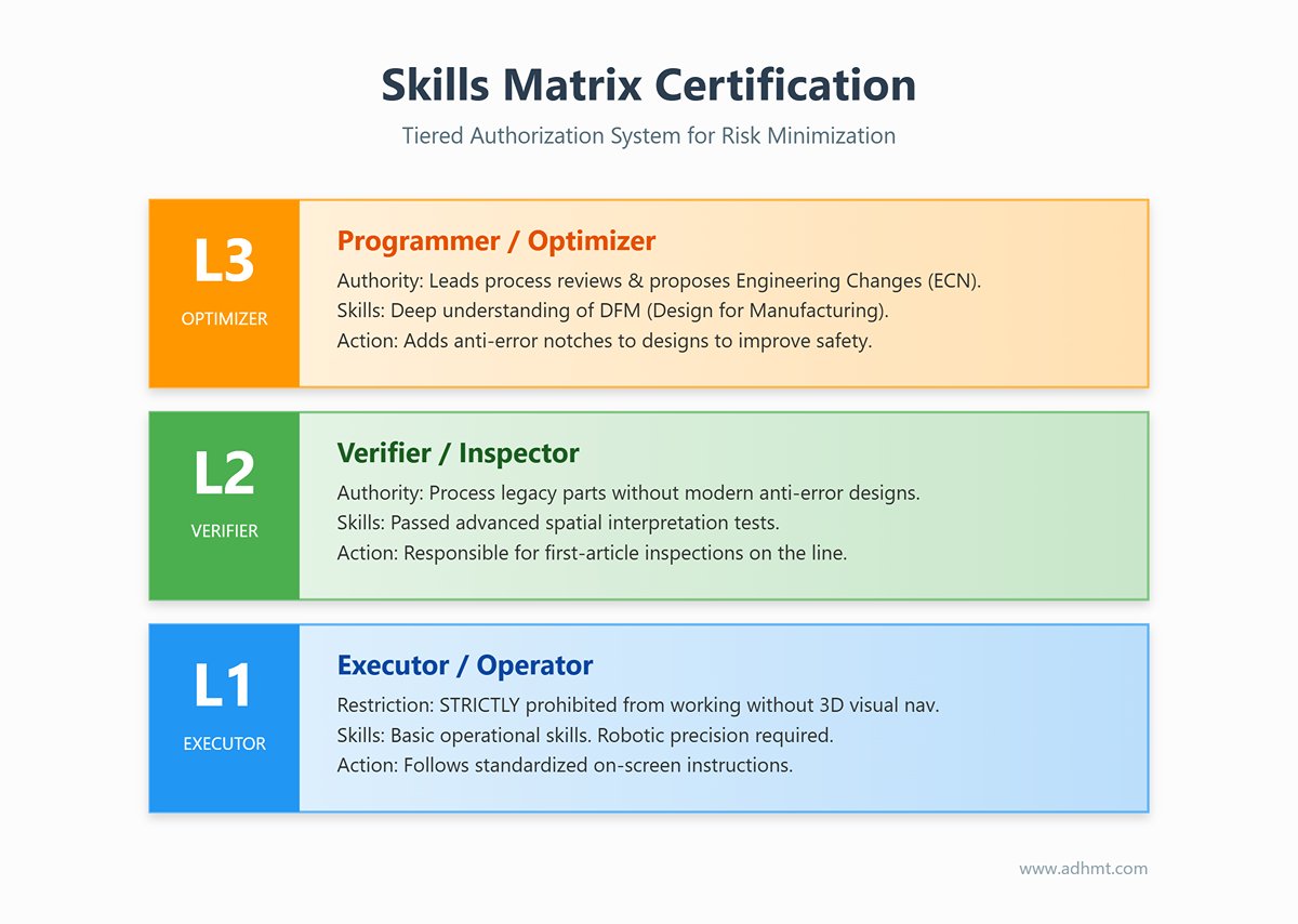
- Level 1 (Executor): Possesses only basic operational skills. Strictly prohibited from working without 3D visual navigation or processing parts lacking physical anti-error features. Their tasks are fully standardized—executed with robotic precision following on-screen instructions.
- Level 2 (Verifier): Has passed advanced spatial interpretation tests. Authorized to process legacy parts without upgraded anti-error designs and responsible for first-article inspections on the line.
- Level 3 (Programmer/Optimizer): Understands DFM (Design for Manufacturing) principles, participates in new product process reviews, and can propose engineering change notices (ECNs) to add anti-error notches to designs.
5.2 Management Innovation: Using Systems to Counter Human Weakness
Management expert W. Edwards Deming once said, “94% of problems come from the system, only 6% from people.” If the culture punishes every mistake with fines, the result will be a workshop filled with fear, dishonesty, and hidden risks. We must instead foster a transparent culture that focuses on root causes rather than blame.
1. Gamified “Zero Scrap” Management: Repetitive work can be a killer of attention. By turning quality control into a game, we can harness dopamine to maintain focus:
- Streak Rewards: Install a digital board in a visible location showing the number of consecutive days without a reverse bend in each team. Set milestones (e.g., 30, 60, 100 days). Upon reaching them, reward the team immediately—with treats, small cash bonuses, or lottery prizes. This shared honor fosters mutual oversight and peer accountability.
- Bug Bounty: A disruptive approach that encourages operators to “hunt for flaws.” If an operator discovers a drawing missing an anti-error notch or finds ambiguity in an SOP’s orientation mark, and the report is verified, they receive an immediate bonus of 50–100 RMB. Far from offending the design team, this turns frontline operators into vigilant process auditors—eliminating risks before production even begins.
2. Error Reporting and the “Five-Minute Golden Rule”: The real danger of reverse bending lies not in the material cost but in concealed corrections—when operators quietly try to fix or hide mistakes, letting defective parts slip through and multiply downstream. What we truly need to buy is honest information flow.
- Non-Punitive Reporting: Establish a strict rule—if a reverse bend occurs, as long as the operator stops the machine and reports it truthfully within five minutes, no financial penalty will be imposed.
- Value Logic: This leniency is not indulgence—it’s damage control. Prompt reporting allows managers to immediately arrange laser cutting for replacement parts (solving the “orphan part” issue) and prevents delivery delays. We trade a small material cost for invaluable production time.
3. Reverse Improvement Loop (Kaizen Loop): Every reported mistake should trigger a system upgrade—not just a repair or reprimand.
- Design-Level “Death Sentence”: Any part scrapped due to directional confusion must have its drawing version “retired.” The design department must respond within 24 hours with a new engineering change order (ECO), adding physical anti-error features or etched markings.
- No-Repeat Principle: “No repeat error” doesn’t mean people never err twice—it means the same drawing must never allow the same person to make the same mistake again. Only when mistake-proofing measures are embedded into both drawings and hardware is the management loop truly complete.
VI. Implementation: The 90-Day Transformation Roadmap
Eliminating reverse bending isn’t a sprint—it’s a systemic transformation spanning from physical environment to cognitive habits. Many workshop initiatives fail because they try to fix everything overnight. To ensure sustainable change, we’ve designed a phased, measurable 90-day action map that enables smooth transition without disrupting production.
6.1 Phase One: Stop the Bleeding and Diagnose (Weeks 1–2)
Strategic Objective: Make hidden costs visible, halt ad hoc fixes, and establish the fundamental physical baselines.
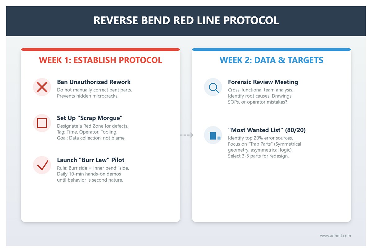
- Week 1: Establish the “Reverse Bend Red Line Protocol”
- Ban Unauthorized Rework: Issue a company-wide notice: any part bent in the wrong direction must not be manually corrected on-site by bending it back. Though such fixes may appear to save time, they actually conceal microcracks that compromise product integrity.
- Set Up a “Scrap Morgue”: Designate a clearly marked red zone on the shop floor. All incorrectly bent parts must be placed there with tags showing the time, operator, tooling, and drawing number. This is not about blame—it’s about data collection. Only by confronting the growing pile of scrap can the team truly grasp the scale of the issue.
- Launch the “Burr Law” Pilot: Select one production line or team as a pilot group to enforce a single rule—the burr side = inner bend side (or a specified direction). The team leader must conduct at least a 10-minute hands-on demonstration in each morning meeting until the behavior becomes second nature.
- Week 2: Data Collection and Target Identification
- Forensic Review Meeting: Use the scrap data collected in Week 1 to hold a short cross-functional meeting (design, process, production). Identify the true root causes: unclear drawing perspectives, ambiguous SOP descriptions, or simple operator mistakes?
- Issue the “Most Wanted List”: Apply the Pareto principle (80/20 rule) to identify the 20% of parts causing 80% of reverse-bend errors. These are typically “trap parts” with nearly symmetrical geometry but asymmetrical bending logic. These 3–5 parts will become the key targets for technical redesign in the next phase.
6.2 Phase Two: Systematic Implementation (Month 1)
Strategic Objective: Materialize the “4D Error-Proofing System” and shift from reliance on human attention to reliance on engineered safeguards.
- Weeks 3–4: Engineering and Process “Gene Editing”
- Targeted Error-Proofing Enhancements: Apply engineering change orders (ECO) to the “Most Wanted” parts identified earlier. Introduce asymmetrical anti-reversal tabs or off-center holes in CAD models, or add directional arrow etching to laser-cut programs. The goal: make it physically impossible to install a part incorrectly.
- Visual SOP Revolution: Eliminate text-only work instructions. For pilot lines, create “Lego-style manuals” with 3D formed images enclosed in frames, highlighted by red circles, and clear icons indicating burr direction.
- Weeks 5–8: On-Site Hardware and Digital Integration
- Physical Workstation Segregation (5S): Enforce strict zoning around bending machines: left side for “to-be-processed” parts, right side for “finished” parts, separated by yellow tape to prevent semi-finished items from re-entering the process. Implement “shadow management” for tooling to ensure correct mold selection and eliminate confusion that leads to directional errors.
- Introduce “Digital Twin Lite”: If full 3D programming isn’t yet supported, implement a low-cost alternative: generate rotatable 3D PDFs or mobile-viewable models for complex parts, and attach QR codes to machines or SOPs. Mandate that operators scan and view the 3D model before starting any asymmetric bending operation.
6.3 Phase Three: Cultural Reinforcement and Optimization (Months 2–3)

Strategic Objective: Transform temporary measures into lasting organizational capabilities, embedding a self-correcting and motivational system.
- Month 2: Skill Grading and Scaled Replication
- Certification-Based Operations: Reassess operator skills based on performance over the previous two months. Build a “skill matrix”; those who pass spatial rotation and error-proofing tests earn a “Level 2 Certification,” receiving preferential scheduling and pay. Uncertified workers handle only simple, symmetrical parts.
- Pilot Expansion: Evaluate pilot line results (error-rate reduction, scrap cost savings). Replicate the proven combination of “Burr Law + Laser Arrow + Visual SOP” across the remaining 80% of machines in the workshop.
- Month 3: Closed-Loop Improvement and Incentive Alignment
- Establish a “Bug Bounty” Program: Institutionalize the practice of “spotting flaws.” Any operator who identifies a missing error-proofing feature on a drawing or ambiguity in an SOP receives an immediate cash reward (e.g., ¥50–100) upon verification. This turns frontline operators from “error makers” into “process auditors.”
- Create a Kaizen Logbook: Each reverse-bend incident must now lead to a specific corrective action—design update, mold adjustment, or process improvement—rather than ending with blame.
- ROI Visualization Report: At the 90-day mark, present a management report written in financial terms: not just a curve showing reduced error rates, but a clear calculation of the real monetary gains from reduced scrap and rework. Demonstrate that every dollar invested in error-proofing directly translates into profit.
VII. Conclusion
How to Stop Press Brake Operators from Bending Parts Backwards is not about blaming workers; it is about fixing a broken system. A single reverse bend destroys material integrity, disrupts production flow, and drains profit far beyond the cost of scrap metal. Instead of relying on "paying attention," this guide introduces a 4D Zero-Error System—combining physical Poka-yoke, standardized "Burr Rules," and digital twin technology—to transform your shop floor from a game of chance into a fortress of precision.
By replacing human vigilance with asymmetric design, implementing strict process standards, and leveraging smart hardware, you ensure correctness is the only possible outcome. The choice is simple: continue paying for invisible scrap, or invest in a system that locks out errors for good.
If you are ready to stop the bleeding and start the precision with equipment that supports digital twin visualization and sensor-based error proofing, ADH Machine Tool—with over 20 years of expertise in high-precision bending—has the solution. To explore more about how our advanced machinery can help you build a truly error-proof bending environment, feel free to contact us.


