I. Introduction
The press brake is a commonly used machine tool in sheet metal fabrication, which is designed for metal sheet bending and forming. It aims to offer precise bending via various metals like steel, stainless steel). The common type of press brake is mechanical press brakes, manual press brakes, hydraulic press brakes, CNC press brakes.
And this bending machine is widely used in many aspects like automotive, aerospace, architecture, and manufacturing. It is crucial to install the press brake correctly. A well-installed machine can not only ensure quality and accuracy but also can ensure the safety of operators.
However, if the press brake is not installed well, it may produce undesired bending results, cause machine damage and bring potential risks to press brake operators and machines. In our passage, we will delve into the whole process of the press brake installation. Watch the video first.
Ⅱ. Core Understanding: Why “Installation Accuracy” Directly Determines “Profitability”
In the metal forming industry, the press brake is often regarded as the heart of the workshop. Yet, most managers and operators focus on tonnage, open height, or the sophistication of control systems—while gravely underestimating the decisive role of initial installation. The harsh reality is this: a poorly installed high-end press brake can perform worse than a perfectly installed mid-tier machine.
Installation is far more than just physically setting the machine in place—it establishes the baseline for precision throughout the equipment’s lifecycle. This chapter explains why installation accuracy has a direct impact on your company’s financial performance and builds a sound engineering mindset.
2.1 Hidden Link Between Installation Quality and Long-Term Cost
Many business owners see installation as a one-time expense, unaware that small deviations at the start can evolve into ongoing “profit leaks” during production.
- Precision Equals Profit: A press brake converts micrometer-level ram movement into angular control. A minor installation error—such as a base twist of just 0.1mm per meter—can result in a 1°–2° bend deviation on a 3-meter workpiece. This forces operators to spend excessive time on trial bends and compensations, raising scrap rates and slashing productivity. In precision sheet metal fabrication, installation accuracy is the physical barrier between profitability and waste.
- Premature Wear and Hidden Damage: Improper leveling places the frame under constant internal stress—like a person working for years with a twisted spine. This imbalance can lead to:
- Hydraulic System Aging: Uneven cylinder loading accelerates one-sided seal wear, causing leaks or unstable pressure over time.
- Guide Rail Damage: The ram guides endure abnormal lateral force and friction, potentially causing irreversible mechanical scoring that shortens the equipment’s designed lifespan by over 30%.
- Safety Foundation: Industry data shows that 40% of sudden equipment failures trace back to unresolved issues from commissioning. Installation affects not only performance but also forms the first line of defense in workshop safety. Loose anchor bolts or incorrect hydraulic connections can quickly escalate into severe accidents.
2.2 Key Concept Explained: Frame Neutrality
Before any physical adjustments begin, it’s vital to understand the guiding principle of press brake installation—Frame Neutrality.
This concept is often overlooked by non-specialist installers. Although the press brake frame is built from thick welded steel plates, it is not an absolute rigid body but an elastic structure.
- Definition: “Frame Neutrality” means that before tightening the anchor bolts, the machine must rest solely on its designed support points in a natural, untwisted, and unstressed state.
- Core Logic: If anchor bolts are tightened before the frame reaches its natural level, the floor’s unevenness becomes “locked” into the machine structure. These locked-in stresses cause the ram to move with a slight spiral trajectory, making consistent bending angles impossible—no matter how advanced the CNC compensation system is.
- Practical Rule: Level first, anchor later. Precision begins only when the machine can “breathe” free from internal stress.
2.3 Scope and Red Lines
This guide provides standardized procedures for technicians working with hydraulic, servo-electric, and hybrid press brakes. However, strict adherence to the following “red lines” is essential to distinguish between safe in-house tasks and those requiring certified professionals:
- ✅ May Be Performed by In-House Technical Teams (DIY Scope):
- Site planning and foundation preparation.
- Equipment unloading, unpacking, and initial cleaning.
- Mechanical positioning and rough leveling (using a spirit level).
- Assembly of non-electrical auxiliary components (such as front support arms).
- ⛔ Must Be Performed by Manufacturer or Certified Experts (Absolute Red Lines):
- High-voltage electrical connections: Any work involving 380V/480V power input must be done by licensed electricians. An incorrect phase sequence can instantly destroy the hydraulic pump motor.
- Precision parameter adjustments: Operations involving CNC core logic, servo-axis PID tuning, or encoder origin settings must be carried out by authorized engineers. Unauthorized changes typically result in immediate warranty voidance.
- Initial power-up commissioning: Most manufacturers require the first power-on to occur under factory supervision to verify the safety circuit’s integrity.
With these principles and boundaries clearly understood, we can safely and professionally move into the preparation stage for installation.
Ⅲ. Phase 0: Strategic Preparation Before Arrival
Pre-installation work is often underestimated, yet it marks the dividing line between an “acceptable” installation and a “flawless” one. Just as a building’s strength depends on its foundation, the press brake’s long-term precision depends on its environment. It’s time to abandon the notion that “placing the machine is enough” and treat preparation as a strategic engineering operation.
3.1 Physical Site Requirements
The physical environment is the press brake’s “soil for survival.” Any compromise here will be magnified many times in final product precision.
- Foundation Load and Flatness: Reject Generic Standards
- Thickness and Grade: Don’t rely on the typical “6-inch (150mm) floor” rule. For machines under 100 tons, C25/3000 PSI concrete with a minimum thickness of 150mm is generally sufficient. For medium and large machines (200 tons or more), a 300mm (12-inch) independent double-reinforced foundation is mandatory.
- Flatness Tolerance (Critical Metric): While many manuals allow looser tolerances, for top-level performance it’s recommended to maintain floor levelness within ±5mm per 10m. Excessive unevenness can cause microscopic frame distortion under gravity that shims cannot fully correct—resulting in inconsistent bending angles along the workpiece length.
- Spatial Planning Logic: Allow for “Invisible Space”
- Backgauge Travel Space: Often overlooked. When planning depth, follow this formula:
Machine physical depth + Maximum backgauge travel (X-axis) + 1000mm (maintenance access). For long sheet workpieces, also reserve additional space for “maximum sheet overhang” to prevent material from hitting walls.
- Backgauge Travel Space: Often overlooked. When planning depth, follow this formula:
- Material Flow Efficiency: Ensure at least a 3‑meter turning radius is reserved for forklifts, and position the sheet‑storage area directly in front or slightly to the side of the machine. Avoid transporting heavy sheets across the operator’s workspace—this directly impacts cycle time once production begins.
- Environmental Adaptation Rule (48‑Hour Principle)
- Thermal Equilibrium: When the machine moves from a transport truck—possibly exposed to outdoor temperature extremes—into a temperature‑controlled workshop, its massive metal body requires time to reach thermal balance.
- Seal Recovery: Even more critical, yet often overlooked, is the condition of hydraulic seals. During transport, vibration and temperature fluctuations place microscopic stress on these components. The machine must remain idle for at least 48 hours—not only to achieve thermal relaxation but to allow the seals to regain their normal elastic modulus. Pressurizing too soon may cause micro‑leaks or premature failure due to stiffened seals.
3.2 Setting Up the “Arsenal”: Essential Tools and Consumables
A professional installation toolkit is an extension of the engineer’s capability. Forget the “one‑wrench‑fits‑all” approach—precision and safety demand the following equipment:
- Precision Measuring Instruments: The Benchmark of Accuracy
- Machining Level: Accuracy must reach 0.02 mm/m. Common construction levels (0.5 mm/m) are useless here—a base deviation of just 0.05 mm can translate into a 0.5‑degree angular error at the end of the ram’s stroke.
- Dial Indicator and Magnetic Stand: Used to check the parallelism and repeatability of the ram’s motion—the ultimate test of the machine’s geometric precision.
- Laser Tracker (Optional): For large press brakes over six meters, conventional levels are inefficient and accumulate error. A laser tracker is the only tool capable of quickly establishing a full‑length reference baseline.
- Heavy Equipment: The Safety Red Line
- Crane/Forklift Selection: Never rely solely on total weight. The press brake’s center of gravity (CoG) is typically far forward, near the cylinders and ram. The forklift’s load‑center distance must cover this CoG; otherwise, tipping is highly likely.
- Heavy‑Duty Skates: Use polyurethane‑wheel skates—they can bear extreme loads while protecting epoxy flooring from cracking.
- Critical Consumables: More Than Just Parts—They’re Protection
- Anchor Bolt Selection:
- Chemical Anchors (Highly Recommended): Resin‑bonded anchors generate no expansion stress, offer superior vibration resistance, and completely fill voids to prevent loosening—ideal for precision machinery foundations.
- Expansion Bolts (Avoid): These rely on mechanical tension. Continuous hydraulic vibrations can gradually loosen them, even cracking the concrete base and disrupting the leveling.
- Precision Shims: Prepare industrial‑grade stainless‑steel shims in varying thicknesses (0.05 mm, 0.1 mm, 0.5 mm, 1 mm). Never use rusty iron sheets or randomly cut scrap to level the machine—this is unprofessional and corrosion will eventually cause precision drift.
- Hydraulic Oil Selection:
- ISO 46: The standard choice for workshops between 10 °C and 40 °C. Offers superior film strength and protects pumps under high pressure.
- ISO 32: Suitable only for cold regions (below 10 °C for extended periods) or small, low‑pressure machines to ensure fluidity during cold starts.
3.3 Pre‑Verification of Energy and Media
Before physical installation begins, confirm the purity and stability of the machine’s “blood” and “nervous system.”
- Power Supply: Prevent Instant Catastrophe
- Voltage Stability: Ensure continuous supply fluctuations remain within ±5%. Some imported servo motors are extremely sensitive—exceeding this range may trigger repeated drive faults or even burnout.
- Phase Sequence Check (L1, L2, L3): The first step before wiring. Always use a phase‑sequence meter to verify the three‑phase order. If the hydraulic pump runs in reverse, a few seconds of dry friction can cause catastrophic damage, resulting in tens of thousands in direct losses.
- Air and Hydraulic Systems: The Necessity of Purification
- Hydraulic Oil Filtration: Remember, “new oil” doesn’t mean “clean oil.” Barrel‑packed industrial oil often fails to meet servo‑valve cleanliness standards. Always use a filter cart with a 10‑micron element when filling the tank—never pour directly from the barrel. This intercepts contaminants and protects delicate hydraulic valves.
Ⅳ. Stage 1: Heavy Operations—Unloading, Positioning, and Mechanical Assembly
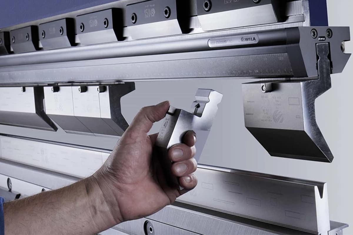
This stage marks the transformation of several tons of precision steel from mere cargo into a high‑accuracy industrial machine. Constant vigilance is essential: despite its rugged appearance, a press brake’s core components are as delicate as a Swiss watch. Any rough handling or incorrect support can cause irreversible mechanical damage and permanent loss of precision—even before power is applied.
4.1 Safe Unloading and Hoisting Procedures
Center of Gravity (CoG) Identification: A Life‑or‑Death Few Centimeters The weight distribution of a press brake is notoriously deceptive. The ram, cylinders, and complex back‑gauge assembly are concentrated at the front, so the CoG rarely aligns with the geometric center—it is usually well forward, sometimes directly beneath the ram.
- Finding the “Golden Point”: Before lifting, consult the manufacturer’s “CoG Map.” Only use the designated lifting eye bolts. For machines with extreme forward CoG, strictly follow the “top‑lift plus rear‑pull” method—use the main top lifting points for load bearing and rear lower tie points with a chain hoist for fine adjustment. This ensures the machine remains perfectly level in mid‑air and prevents tipping.
- Absolute Red Lines (Prohibited Actions): Never thread lifting straps through cylinders, scales, lead screws, or back‑gauge beams. These components cannot bear the machine’s weight—even a minor deformation (as little as 0.05 mm) can destroy cylinder seals or ruin lead‑screw accuracy.
Unpacking and Cleaning: Handling the First Protective Layer Machines are usually coated with a thick yellow rust‑proof wax at the factory. Improper removal can become a silent killer of precision.
- Solvent Choice: Experts recommend using WD‑40 or kerosene to soften the rust‑proof wax, then wiping with non‑woven cloth.
- Prohibitions: Never use metal scrapers to remove grease from guideways, nor aggressive solvents like thinner or acetone. Such chemicals can dull the paint finish and corrode nonmetallic wipers on the ram guides, allowing dust to penetrate later. After cleaning, immediately apply a thin coat of ISO 68 way oil to prevent secondary corrosion of exposed metal surfaces.
4.2 Preliminary Positioning and the “Triangular Support” Principle
Rough Positioning Technique When moving the machine to the foundation markings with heavy-duty skates, take care not to block the pre-drilled anchor bolt holes.
- Practical Insight: Before the machine is set down, loosely pre-install all anchor bolts with nuts into the base holes—do not tighten them. Align them with the foundation holes and lower the machine in one smooth motion. This prevents the frustrating situation where, after placement, slight misalignment makes bolt insertion impossible.
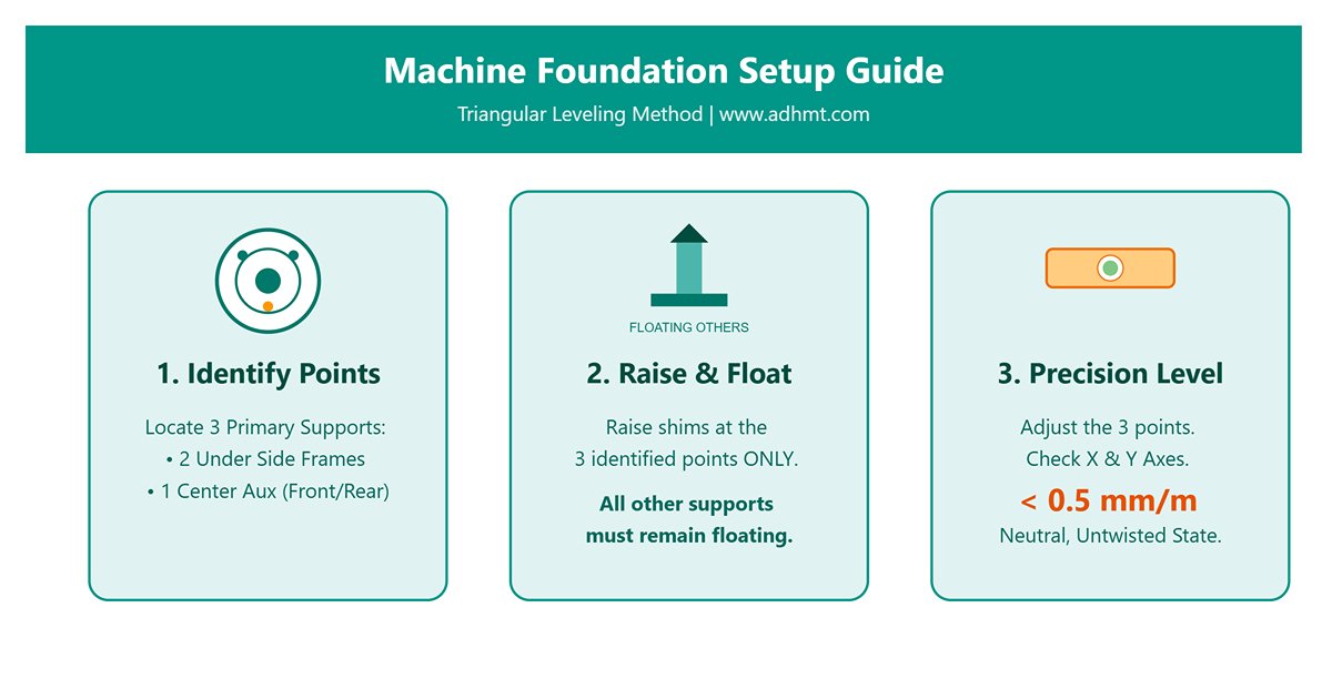
The “Triangular Shim” Strategy: The Secret to a Stable Plane This critical step is often overlooked by non-professionals. According to geometric principles, three points define a plane. During the initial installation phase, regardless of how many adjustment points the machine base has, you must and can only rely on three primary support points to establish initial stability.
- Physical Principle: Adjusting all anchor bolts simultaneously will force the machine frame to twist due to uneven floor levels, creating a distorted structure. Establishing a three-point plane first eliminates internal stress within the frame.
- Procedure:
- Identify two main support points directly beneath each side frame and one auxiliary point in the center of either the rear or front side, depending on the machine model.
- Raise the shims or leveling bolts beneath these three points so that all other auxiliary supports remain completely floating.
- Adjust only these three primary supports. Using a precision level, keep the worktable’s horizontal deviation within 0.5 mm/m along both the X (left–right) and Y (front–back) axes. At this stage, the frame is in a neutral, untwisted state—providing the physical foundation for micron-level fine tuning later.
4.3 Assembly of Split-Type Machines (for Large Equipment)
For press brakes longer than 6 meters or dual-machine linked systems, split transportation is used, and on-site assembly becomes the most technically demanding part of the installation.
Joining the Side Frames and Beam: The Art of Torque The connecting bolts for large frames are typically high-strength grade 12.9 large-diameter bolts, and their tightening process must be executed with surgical precision.
- Critical Warning: Never use an impact wrench for random tightening. Its torque output is unstable and uncontrolled.
- Standard Procedure: Always use a hydraulic torque wrench. Apply torque in three progressive stages (30% → 70% → 100% of target value) following a “star” or “diagonal” pattern. This gradual tightening ensures uniform pressure across the joint surfaces and prevents localized stress that could deform the frame.
Optical Calibration of Geometric Perpendicularity For large-frame assembly, traditional squares can no longer meet precision requirements.
- Core Objective: Employ a laser alignment tool or a high-precision theodolite to ensure that both side plates are not only parallel to each other but also perpendicular to the base plane within a deviation of 0.05 mm/m.
- Warning: Even a minute error in perpendicularity can generate significant lateral forces during the slide’s downward travel, leading to rapid wear of expensive guideway systems and producing bending angle variations along the full length that are impossible to compensate.
Ⅴ. Stage 2: Core Geometric Precision Tuning (The Heart of Precision)
At this stage, the goal is no longer to make the machine merely “look straight,” but to achieve micrometer-level geometric perfection. If the previous phase built the skeleton, this one breathes life into it. Here lies the battlefield that determines whether your machine produces standard parts or precision masterpieces—any compromise will inevitably show up as scrap costs in your financial reports.
5.1 X-Axis (Left–Right) Level Fine Adjustment: Finding the Absolute Reference
Most installation errors originate from incorrect measurement positions. Many beginners place the level on the table edge or T-slots—a fatal mistake.
- True Meaning of Measurement Reference: The only authentic reference surface of a press brake is the machined mounting surface of the lower die holder. This finely ground surface directly determines the die’s alignment.
- Operation: Clean this surface thoroughly using nonwoven fabric and cleaning solution to remove rust-prevention residues and burrs. Place a precision level (accuracy 0.02 mm/m) at both the far left and right ends of the table, ensuring consistent reading direction.

- Adjustment Sequence: The Art of Stress Release True experts never force the frame into alignment with bolts—they let stress dissipate naturally through controlled “floating and settling.”
- Lifting: Use the leveling jackscrews on the base to fine-tune the height until the level’s bubble is perfectly centered.
- Gap Measurement: At this point, the entire machine weight rests on the screws. Measure the gap beside each jack using feeler gauges, then combine stainless-steel precision shims of corresponding thickness (recommended stack: 1 mm + 0.1 mm + 0.05 mm).
- Settling (Critical Step): After inserting the shims, be sure to loosen the jackscrews, allowing the frame to naturally settle and compress the shims.
- Verification: Check the level again. If the reading changes by more than 0.02 mm/m, the frame may be elastically deformed or have a “floating leg.” Recalculate shim thickness and repeat until the frame sits firmly on the shims.
- Target Tolerance: Although the industry standard permits up to 0.1 mm/m deviation, to ensure the twin hydraulic cylinders share equal load distribution and prolong seal life, we require the X-axis level error to be strictly within 0.05 mm/m.
5.2 Y-Axis (Front–Back) Perpendicularity and Parallelism: Eliminating the “Twisting Syndrome”
If the machine frame is imperceptibly twisted during installation, even the most advanced CNC system cannot fully correct the resulting angular errors.
The Butterfly Effect of Verticality on Bending Angles
If the left side of the frame tilts forward by 0.1° and the right side leans backward by 0.1°, the upper die’s downward path will strike at two different points. This microscopic misalignment produces a clear taper error, often seen as one end of the workpiece having a larger bend angle than the other—a problem no backgauge adjustment can fix.
Diagnosis and Correction of Twisted Bed Syndrome
- Diagnosis: Attach two precision levels to the machined vertical surfaces of the left and right side frames. Compare their readings—if the left shows +0.05 and the right −0.05, the machine is in a twisted, “corkscrew” state.
- Correction: Use the tension of the anchor bolts together with the thrust of the jacks to create a force couple. Fine-tune the front or rear foot on one side of the frame until the vertical readings on both side plates are perfectly identical. This is the only physical method to eliminate structural twisting.
Verification of Parallelism Between the Ram and the Worktable
- Procedure: Attach a magnetic dial stand to the lower worktable and position the dial gauge probe against the underside of the ram (or the clamping surface of the upper die). Bring the ram to a position roughly 100 mm above bottom dead center (BDC). Manually move the stand along the X-axis or across the full length of the ram.
- Standard: The full-length reading variation should be less than 0.03 mm. Exceeding this tolerance typically indicates an error in the ram guide alignment or a mismatch in the cylinder synchronization reference. This must later be corrected by fine-tuning the Y1/Y2 axis origin parameters in the CNC system (a procedure generally requiring manufacturer authorization).
5.3 Anchoring and Stress Relief: The Magic of Time
When you think the leveling is perfect—pause. Physics reminds us that materials need time to settle into their new posture.
- Settling Period (24-Hour Rule): After the initial leveling is complete, never lock down the anchor bolts immediately. The concrete foundation will undergo microscopic creep, and multiple shims will further compact under load. The machine must remain stationary for at least 24 hours. When you recheck the next day, you’ll often find the level has drifted by 0.02–0.05 mm. That’s why “install today, run today” is the sworn enemy of precision.
- Final Tightening: The Eagle Eye Principle
- Sequence: Once rechecked and confirmed, tighten the anchor bolts using a calibrated torque wrench. Follow a diagonal cross pattern (similar to tightening car wheel nuts), gradually reaching the specified torque in three steps.
- Warning: Keep your eyes fixed on the level bubble at the exact moment each bolt is tightened. Bolts are meant to lock the position, not to change it. If the bubble moves, that point is under uneven stress—stop immediately, loosen the bolt, and readjust the shim thickness. Trying to achieve leveling by simply tightening bolts injects destructive stress into the machine frame.
Ⅵ. Phase 3: Fluid Power and Electrical System Integration
If the mechanical structure forms the “skeleton” of the press brake, the hydraulic system is its “blood,” and the electrical system its “nerves.” At this stage, the equipment is physically in place—but as you prepare to “breathe life” into it, even the smallest oversight—be it a microscopic metal chip or an incorrect power phase—can trigger a catastrophic event before production even begins: an electrical “stroke” (short circuit) or a hydraulic “clot” (valve seizure).
6.1 Hydraulic System Commissioning for Clean Operation
Initial commissioning of the hydraulic system is far more than simply “fill and start.” For modern press brakes equipped with precision proportional servo valves, it’s a battle against microscopic contaminants.
Cleanliness Protocol: Debunking the Costly Myth of 'New Oil = Clean Oil'
- Core Insight: Many users assume that freshly opened barrels of hydraulic oil are perfectly clean. This is a dangerous misconception. Typical industrial-grade new oil often has an ISO cleanliness level of 18/16/13 or worse, while servo valves require at least ISO 16/14/11 to function properly. Pouring in “dirty” new oil is essentially feeding abrasive grit to precision valve spools.
- Mandatory Measures: Never pour oil directly from the barrel into the tank. Always use a filtering cart equipped with a 10-micron (or finer) filter element for pumping and filling. For machines using high-end Hoerbiger or Bosch Rexroth hydraulic systems, it’s strongly advised to install flushing blocks in place of servo valves before the first startup and perform a 2–4 hour idle circulation flush. This ensures that residual weld slag or metal particles are completely filtered out, protecting expensive valve components from any risk.
Oil Filling and Air Purging: Eliminating the Cavitation Killer
- Jogging Technique for Air Purge: When starting the motor for the first time, never let it run continuously. Use short “jog” cycles of 1–2 seconds each, repeated 5–10 times. This allows the pump to build up a lubricating oil film before full pressure is established.
- Acoustic Diagnosis: Listen carefully to the pump sound. A sharp “whine” or a noise resembling gravel being churned inside the pump indicates cavitation—air has entered the suction line or the intake is blocked. Stop immediately and inspect the suction hose seals and strainer.
- Cylinder Air-Purge Procedure: With the system set to its lowest pressure mode, run the ram slowly through its full stroke 10–15 times. At each top dead center (TDC), loosen the bleed screw on top of the cylinder (if equipped) until the escaping oil runs clear and bubble-free. Even small air residues can cause ram judder or a “spongy” effect, leading to unstable pressure accuracy.
Leak Prevention: Stepwise Pressure-Holding Test
Do not rush to full pressure. Use a stepwise testing approach to verify system sealing:
- 30% Pressure: Hold for 10 minutes. Focus on hose fittings and valve block joints; use white paper to wipe connectors for easier detection of oil traces.
- 70% Pressure: Run idle for 30 minutes and observe whether oil temperature rises abnormally.
- 100% Pressure: Proceed to full-load bending tests only after the previous stages pass.
- Watch for Micro-Leaks: Pay close attention to hose joints in high-vibration areas between moving and stationary parts. Tiny oil mist here often signals an impending high-pressure hose failure.

6.2 Electrical Connections and Logic Verification
Electrical connection is not merely about powering up—it’s about establishing the logical foundation of the machine. Incorrect wiring can make the system behave erratically or instantly destroy key components.
- Phase Sequence and Motor Direction: A One-Second Matter of Life and Death
- Critical Warning: The hydraulic pump must never run in reverse! Even a few seconds of reverse dry friction can scorch the pump’s distribution plate, generating metal debris that contaminates the entire hydraulic circuit—causing tens of thousands in direct losses and lengthy cleanup.
- Verification Procedure:
- Check with Instruments: Before connecting the motor’s main power, use a phase rotation meter to measure the incoming line and ensure the phase sequence matches the machine’s requirements.
- Physical Confirmation: If a phase meter is unavailable, temporarily disconnect the coupling between the pump and motor (if design permits), or “jog” the motor briefly (0.5 seconds) and observe whether the fan’s rotation direction matches the arrow marked on the motor casing.
- Grounding Standards: The Shield Against Signal Interference
- CNC controllers, servo drives, and linear scales are extremely sensitive to electromagnetic interference (EMI). Poor or unstable grounding can cause screen flickering, erratic coordinate readings, or even random system crashes.
- Dedicated Grounding: Ground resistance must be less than 4 ohms. Never connect the ground wire to workshop steel columns or water pipes—these are considered “dirty” grounds. Always connect to a properly installed, deeply buried grounding rod.
- Equipotential Bonding: Confirm that the machine frame, electrical cabinet doors, and control console are linked with braided copper straps. Proper equipotential bonding eliminates floating voltages and ensures a clean reference zero point for CNC signal transmission.
- Peripheral Device Integration and Safety Logic
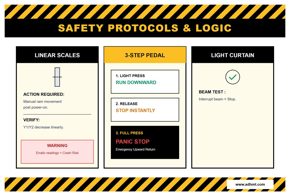
- Linear Scales: These are the core feedback components of closed-loop control. After powering on, manually move the ram and verify that the Y1/Y2 readings on screen change linearly and that the counting direction is correct (typically, values decrease as the ram moves downward). If readings jump erratically or move in the opposite direction, homing will fail and the ram could crash into the base.
- Foot Pedal Logic: Confirm the standard three-step operation—light press to run the ram downward (Run); release to stop immediately (Stop); press fully to trigger an emergency stop (Panic Stop) and initiate an upward return.
- Safety Light Curtain Test: This is more than a functional check—it defines legal liability. Use a standard test rod to interrupt the beam; the ram must stop instantly within the specified stop time. For systems equipped with a muting function, verify that during slow downward motion the light curtain correctly switches modes without generating false alarms.
Ⅶ. Phase 4: CNC Initialization, Calibration, and Trial Operation
Once the mechanical structure is firmly in place and the hydraulic system flows cleanly, it’s time to awaken the press brake’s “brain”—the CNC control system. This stage is not merely about powering up the display; it’s about translating the micron-level mechanical precision established earlier into digital control accuracy through parameter mapping, achieving true “what you see is what you bend” performance.
7.1 System Power-Up and Homing
Starting up the CNC system is not as simple as pressing “ON.” It marks the first step in establishing trust between human and machine. Any hasty action can lead to data loss or mechanical collision.
- Initialization Check: Reading the Machine’s First ‘Breath’
- Alarm Interpretation: Upon startup, a series of alarm codes will inevitably appear. Avoid the reflex to repeatedly hit “Reset.” A true professional reviews each message carefully. Normal alarms typically include “Reference Missing,” “Emergency Stop Pressed,” or “Pump Not Running.”
- Critical Red Flags: If you see “Drive Communication Error” or “Encoder Count Error,” do not attempt to force a reset or start the hydraulic pump. These usually indicate loose wiring, poor servo connections, or incorrect phase sequence. Running the machine under these conditions can easily destroy expensive servo drive boards.
- Parameter Backup (The Safety Net): Before changing any parameter, always create a complete backup. Insert an industrial-grade USB drive and navigate to the system’s maintenance menu (e.g., Delem:
Settings > Backup/Restore) to back up both “Machine Parameters” and “Sequencer.” Should parameter confusion occur later, this backup will be your only lifeline.
- Standard Homing Sequence
- Modern press brakes typically use incremental linear scales. After each power cycle, the system must physically locate a reference point (Index) to establish its coordinate system.
- Operation Procedure: Start the main hydraulic pump → visually confirm that the ram and backgauge area are clear → press the green start button. The standard homing logic is: the Y-axis (ram) first moves upward to locate the home switch; once Y is confirmed, the backgauge axes (X, R, Z) sequentially move to find their respective reference points.
- Troubleshooting Abnormalities: If the Y-axis continues moving upward until it hits the mechanical hard limit, there are usually two causes: (1) the home sensor is misaligned or damaged, so the system fails to detect it; or (2) the linear scale direction is reversed in the parameters (for example, readings decrease instead of increase as the ram moves up), causing the system to mistakenly send continuous upward commands.

7.2 Practical Accuracy Calibration
Being able to move is not enough; geometric deviations between axes must be eliminated to ensure perfect alignment between digital commands and physical motion.
- Y-Axis Balance Calibration: Eliminating the “Short-Leg” Effect
- Core Issue: Due to manufacturing tolerances or differences in hydraulic line length, the left cylinder (Y1) and right cylinder (Y2) often move with slight asynchrony, causing the ram to tilt during downward motion—accelerating wear on the guide rails.
- Equal-Height Block Method (Block Calibration):
- Place two precision steel blocks or lower dies with identical heights (tolerance <0.01 mm) at the far left and right ends of the worktable.
- Switch to “Manual Mode” and lower the ram at ultra-low speed until it lightly contacts both blocks (verify contact pressure using feeler gauges).
- Open the CNC diagnostic screen and read the real-time Y1 and Y2 linear scale values. If physical contact is confirmed but the display shows Y1=100.00 mm and Y2=100.05 mm, enter a correction of -0.05 mm in
Machine Parameters > Reference Correctionsto level the data baseline.
- Deflection Compensation (Crowning) Calibration
- V-Axis Zero Point: For machines equipped with hydraulic or mechanical crowning systems, verify that when the V-axis value is set to zero, the worktable is perfectly flat.
- Preload Adjustment: For motor-driven mechanical wedge compensation systems, check the chain tension. The compensation gain factor typically requires fine-tuning through test bending. If you observe that the workpiece angle is larger in the middle than at the ends (for example, center 91°, ends 90°), the compensation is insufficient—adjust the V-axis gain upward in the CNC to correct it.
- Backgauge Accuracy
- Finger Parallelism: This is a common blind spot in precision calibration. Attach a dial indicator to the underside of the ram, with the probe touching the front face of the backgauge finger. Move the X-axis across its full travel while manually adjusting the R-axis up and down to ensure that the height difference between the finger top and the lower die surface remains within 0.1 mm across the entire length.
- X/R-Axis Alignment: The front faces of both fingers (Finger 1 and Finger 2) must lie perfectly on the same straight line. Place a precision straightedge flush against the rear face of the lower die, then slowly move the X-axis until the fingers just touch the straightedge. If one side makes contact while the other leaves a gap, loosen the eccentric bolt at the finger’s front end and fine-tune until both sides make simultaneous, light contact with the straightedge.
7.3 Trial Bending and the “Coupon Test”
This is the ultimate exam of all installation work—verifying and fine-tuning the system’s final parameters through actual bending results.
- Three-Point Strategy
- Avoid Waste: Do not use full-size, costly sheets for testing. Prepare three small coupons of identical material (recommended: Q235 cold-rolled steel), thickness (e.g., 3 mm), and width (100 mm).
- Placement Logic: Position the three coupons respectively at the far left, center, and far right of the worktable.
- Unified Operation: In the CNC, set a target angle (e.g., 90°) and enter precise material and tooling parameters. Perform a single bending operation on all three coupons simultaneously.
- Angle Correction and Data Feedback
- Measure the angles of the three coupons using a high-precision protractor, then interpret the results as follows:
- Scenario A: All three coupons show 92°.
- Diagnosis: The overall Y-axis penetration depth is insufficient.
- Remedy: Adjust the total Y-axis depth in the system’s
Global Correctionor tooling parameters.
- Scenario B: Left 90°, right 91°, center 90.5°.
- Diagnosis: The ram is tilted; Y1/Y2 reference points are misaligned.
- Remedy: Modify the
Y1/Y2 Tiltparameter, increasing the Y2 axis penetration slightly.
- Scenario C: Both ends 90°, center 92°.
- Diagnosis: A classic “canoe” deformation—machine deflection not fully compensated.
- Remedy: Crowning compensation is insufficient; increase the compensation value.
- Scenario A: All three coupons show 92°.
- Objective: Iteratively fine-tune until the angle deviation among the three points is within ±0.5° (or ±0.3° for high-precision machines).
- Measure the angles of the three coupons using a high-precision protractor, then interpret the results as follows:

- Consistency Check
- Accuracy must be repeatable, not a one-time success. After completing the above calibration, perform 10 unloaded cycles and 10 loaded bends consecutively. Closely observe whether the ram’s positioning at bottom dead center (BDC) remains stable within ±0.01 mm. Also monitor for any angle drift as oil temperature rises (from 20°C to 50°C). Only after passing this endurance test can the machine be considered truly ready for production handover.
Ⅷ. Phase Five: Safety System Verification and Acceptance (Non-Negotiable)
When the mechanical framework and hydraulic system are in place, the final checkpoint is not production readiness but survival assurance. The sole purpose of this phase is to confirm that under any fault condition or operator error, the equipment can never become a lethal hazard. Remember: any failed safety test must trigger an immediate “red card” shutdown until the issue is fully resolved—there is no such thing as ‘good enough’ in safety.
8.1 Light Curtain Safety Test: No Room for Shortcut Gestures
Many untrained technicians simply wave a hand through the light curtain to see if the ram stops—an act of serious negligence toward operator safety. A professional test must follow rigorous optical and logical validation standards.
- Standardized Penetration Test
- The Test Rod Rule: The test rod must match the light curtain’s resolution exactly. For finger-protection curtains (14 mm resolution), use a 14 mm diameter rod; for palm-protection types (20–30 mm), use the corresponding size. Never use body parts for testing—fingers can pass through the blind zone between two beams undetected.
- Full-Area Scan: During the ram’s downward movement, perform obstruction tests at the upper, middle, and lower edges of the light curtain’s sensing zone.
- Dead Zone Inspection: Pay special attention to the gap between the bottom of the light curtain and the lower die. If operating in “Floating Blanking” mode, confirm that the floating window setting is not so large that a single finger could pass through without triggering an alarm.
- The Mathematics and Pitfalls of the Mute Point
- Definition: The mute point is where the ram transitions from fast approach to slow bending speed. Beyond this point, the light curtain is temporarily disabled (muted) so the sheet can follow the ram’s upward bend without causing an emergency stop.
- Safety Distance Threshold: According to EN 12622 and best practice, the mute point must be set no higher than 6 mm above the sheet surface (some laser protection systems require ≤ 2 mm).
- Mandatory Speed Limitation: Once in mute mode, the ram speed must be physically limited to 10 mm/s or less, regardless of foot pedal pressure.
- Practical Verification: Place a scrap sheet on the die and adjust the mute point so the ram slows just before contacting the material. Warning: If the mute point is set too high (e.g., 20 mm above the sheet), an operator’s fingers could enter the danger zone the instant the light curtain is muted—one of the most frequent causes of press brake hand injuries.
8.2 Mechanical and Electrical Interlocks: The Invisible Safeguard
The light curtain is only the first line of defense—the true determinant of safety lies in the physical response speed of the mechanical and hydraulic systems.
Emergency Stop Response Time Measurement
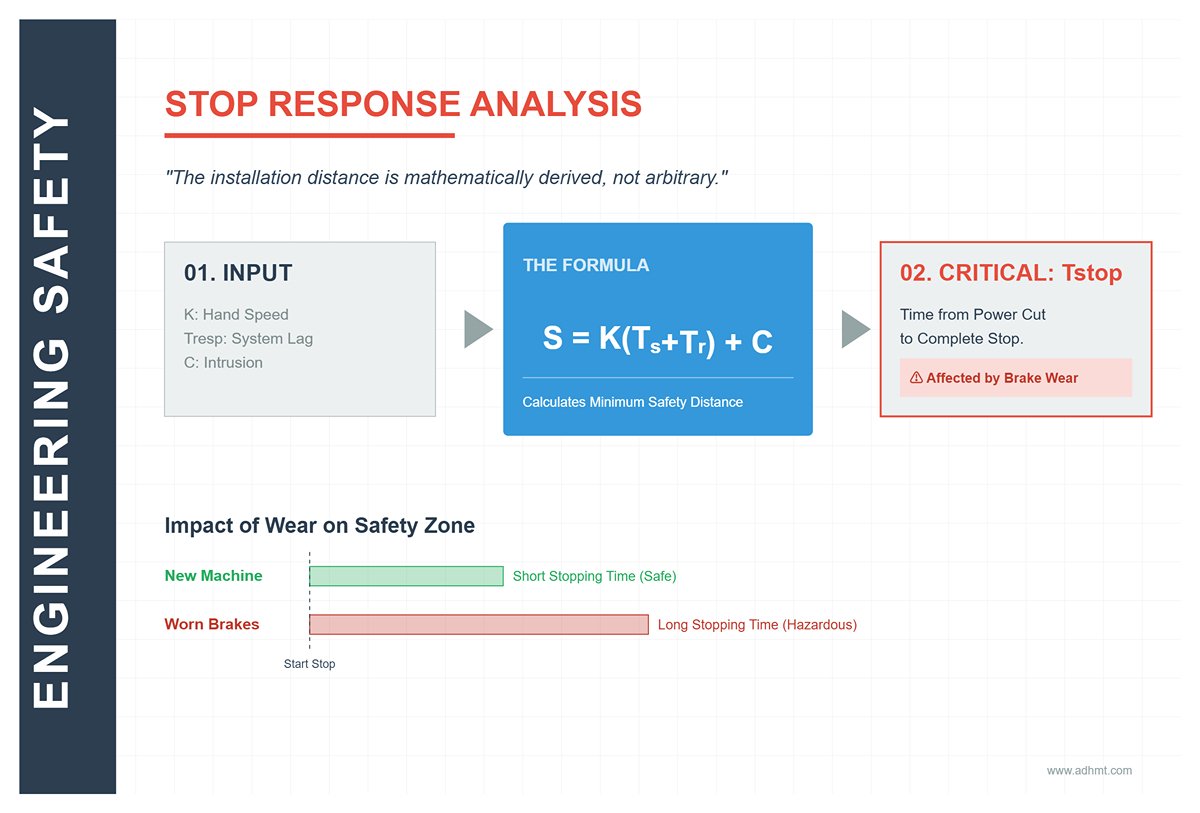
- Physical Principle: The installation distance of the safety light curtain is not arbitrary—it is mathematically derived from the machine’s braking time. If brake wear causes the stopping time to increase, a previously safe curtain position may become a hazardous zone.
- Core Formula Verification:
Here, Tstop represents the time it takes for the machine to come to a complete stop after power is cut.
- Field Measurement: A Stop-Time Meter must be used for this test. Trigger an emergency stop while the ram is moving downward at full speed, then record the travel distance and time. If the measured stop time exceeds the rated value on the machine’s nameplate (for example, deteriorating from 80ms to 120ms), the braking system must be adjusted immediately—or the light curtain repositioned farther from the danger zone (each additional 10ms requires roughly 16mm of setback).
Hydraulic Anti-Drift and Drop Test (Drift Test)
- Hot-Oil Rule: Conduct this test only when the hydraulic oil reaches its operating temperature (approximately 40–50°C). Cold oil’s high viscosity can mask minor seal leakage, creating a false sense of safety.
- Procedure: Position the ram at the top of its stroke, load the maximum die weight, and disconnect the main power supply.
- Acceptance Criteria: Let the machine stand idle for 10 minutes. According to ISO 12622, the ram’s natural downward drift should not exceed 1–2mm, depending on the machine’s tonnage.
- Fault Indication: If the ram visibly descends, it indicates internal leakage in the Prefill Valve or Counterbalance Valve. These components must be replaced before commissioning; otherwise, the ram could drop suddenly under gravity during overnight shutdown or when maintenance personnel reach into the die area.
8.3 Final Acceptance Checklist (FAT – Factory Acceptance Test)
Do not rely on verbal confirmation—always sign a FAT report containing quantified data. This document is not just a technical record; it is your legal protection against accepting noncompliant equipment and a safeguard against future liability.
| Inspection Dimension | Key Checkpoints | Acceptance Criteria / Threshold | Measured Result |
|---|---|---|---|
| Geometric Accuracy | Ram-to-Table Parallelism (Y-axis) | Total deviation ≤ 0.03mm (under no load) | [ ] |
| Process Capability | Angle Consistency | Bending angle deviation at left/center/right ≤ ±0.5° (3mm Q235 carbon steel) | [ ] |
| Hydraulic System | Full-Tonnage Pressure Holding | Maintain 100% system pressure for 10 minutes; pressure drop < 10% | [ ] |
| Safety | Light Curtain and Mute Point Logic | Machine stops when test rod fully interrupts curtain; mute speed ≤ 10mm/s | [ ] |
| Environmental Metrics | Noise and Temperature Rise | Noise < 75 dBA; oil temperature rise < 35°C above ambient | [ ] |
| Electrical Integrity | Cabinet Ground Resistance | < 0.1Ω (PE terminal to any metal point on machine body) | [ ] |
Epilogue: From Installation to Legend
At this stage, your press brake is no longer just a mass of steel and wiring—it has been refined into a precision manufacturing weapon. But remember: the moment installation ends, maintenance truly begins.
Expert Advice: Recheck the machine’s level and anchor bolt torque at both the 30-day and 6-month marks after full-load operation. Micro-settlement of the concrete foundation and stress release within metal components are unavoidable physical phenomena. This guide encapsulates the tacit knowledge of leading industry engineers—may it serve as the ultimate guardian of your workshop’s accuracy and safety.
Ⅸ. Troubleshooting & Maintenance Loop
Perfect installation is only the first step in a long journey. The true lifecycle of a press brake begins the moment it starts bending its first sheet. For seasoned engineers, installation completion does not signify the end—it marks the start of an even more critical phase: fine-tuning and adaptation. How to handle early-stage “soft faults” and establish a rigorous maintenance system is what separates a mere operator from a true equipment expert. This chapter presents a practical troubleshooting logic and maintenance loop based on real-world experience.
9.1 Common Issues During Commissioning (Troubleshooting)
In the first few weeks of operation, seemingly inexplicable malfunctions often occur. These typically stem not from poor manufacturing quality, but from installation stress release, parameter mismatches, or evolving operator habits.
Spongy Ram: Rapid Elimination of Hydraulic Air Entrapment
- Symptom Description: Operators may notice a springy delay when the ram first contacts the workpiece, as if pressing on a sponge. Alternatively, the pressure gauge needle may flutter violently, accompanied by pulsations in the hydraulic lines. This usually indicates trapped air within the cylinders or piping, making the hydraulic fluid—normally incompressible—behave as though it were compressible.
- Expert Troubleshooting Method:
- Avoid Blind Oil Draining: Many novices attempt extensive oil discharge to vent air, which wastes fluid and is inefficient. The correct procedure is to position the ram at bottom dead center (BDC) and switch off the main motor.
- Targeted Bleeding: Loosen the cylinder’s bleed screw about half a turn (never remove it completely) until clear, bubble-free oil flows out, then tighten promptly.
- Low-Pressure Cycling: For systems without dedicated bleed screws, program a low-pressure (around 20–30 bar), full-stroke idle run. Allow the ram to move slowly back and forth 15–20 times. The circulating hydraulic fluid will carry microbubbles back to the tank, where they can dissipate through the baffle mesh.
Uneven Bending Angles: More Than Just a Y-Axis Issue
- Phenomenon Diagnosis: The ram appears perfectly level during no-load operation, yet under bending pressure, one end of the workpiece shows a larger angle than the other.
- In-Depth Diagnostic Logic:
1. Check Frame Rigidity: This is a physical factor that’s often overlooked. If one side’s foundation bolts loosen or the base settles during pressurization, the frame may experience a momentary micro-deflection under load. This dynamic deformation causes the ram on that side to lift slightly, reducing bending depth. Recheck and retighten all foundation bolts to their specified torque values.
2. Proportional Valve Hysteresis: For electro-hydraulic synchronized models (such as those equipped with a Delem control system), if the mechanical structure is sound, enter the system diagnostics page to check the Y1/Y2 valve opening gain. If you notice sluggish response or inconsistent data on one side, the proportional valve coil may have absorbed moisture, or microscopic impurities in new hydraulic oil could be causing the valve spool to stick at a micron level.
- System Errors: Understanding the Machine’s Distress Signals
- Common Error Code Interpretations:
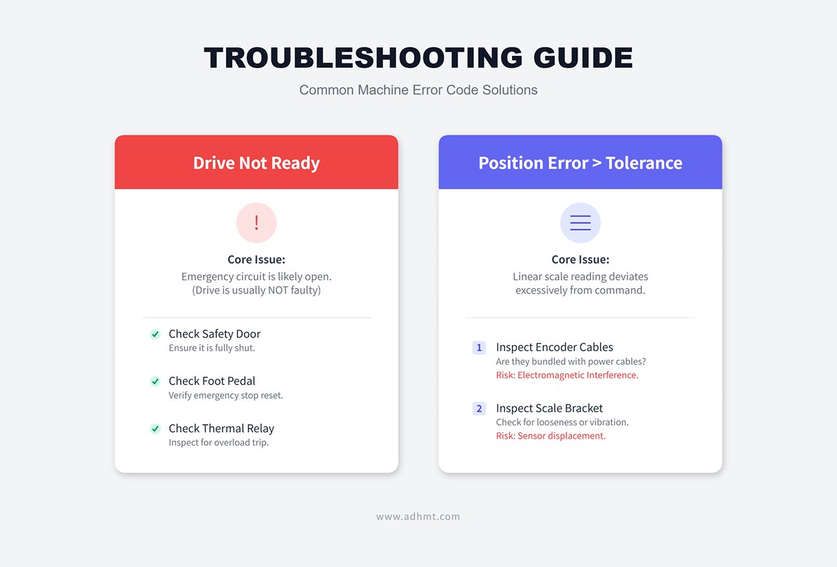
Drive Not Ready: This doesn’t usually mean the drive is faulty. It often indicates that the emergency circuit isn’t closed. Check whether the safety door is fully shut, the foot pedal emergency stop switch is reset, and whether the motor’s thermal relay has tripped due to overload.Position Error > Tolerance: This means the actual reading from the linear scale deviates excessively from the commanded position. First, check whether the encoder cable is bundled together with power cables (which can cause electromagnetic interference). Next, inspect whether the scale bracket has loosened, leading to vibrations and displacement of the sensor.
- Common Error Code Interpretations:
- Soft Reset Tips: Most non-critical soft faults can be cleared using the system’s “Clear Index” or “Reset” functions. There’s no need to power down the entire system each time, which helps reduce reboot and initialization time.
9.2 Managing the “Break-In” Phase of Initial Production
Just like a new car, a new machine requires a break-in period. During this stage, mechanical components settle into alignment, and bolted joints undergo stress relaxation.
- The First 100 Hours: Golden Maintenance Window
- Secondary Bolt Tightening: This step is absolutely essential. After about 100 hours of heavy-duty operation, minor compression often occurs between the foundation bolts and the concrete base. Using a torque wrench at this point usually reveals that nuts can be tightened another quarter turn or more. If this step is skipped, even a 0.5 mm gap could later develop into several millimeters of frame vibration.
- Hydraulic “Dialysis”: In the early operating stage of a new hydraulic system, tiny welding residues from pipe interiors and microscopic rubber particles from seal wear are flushed out. It’s highly recommended to replace the high-pressure filter element and clean the return filter screen after 100 hours of use. Don’t risk damaging expensive servo valves for the sake of saving a few hundred yuan on filters.
- 30-Day Geometric Recheck
- Compensating for Foundation Settlement: No matter how well the foundation was constructed, concrete undergoes micro-creep under the repeated impact of several tons of alternating load. After 30 days of operation, use a precision level (0.02 mm/m) to recheck the X-axis level. If the deviation exceeds 0.05 mm/m, loosen the bolts and readjust the shim thickness immediately. This is your last chance to prevent permanent machine deformation.
9.3 Documentation Management: Creating a “Birth Certificate” for Your Equipment
The biggest challenge many factories face during maintenance isn’t lack of technical skill—it’s missing data. Building a comprehensive technical dossier for each machine is the most strategically valuable part of the maintenance feedback loop.
- Core Value: When a machine suffers a sudden failure three years later, or when OEM engineers perform remote diagnostics, this dossier serves as the “decoder key” to solving the problem efficiently.
- Recommended Archive Contents:
- Initial Parameter Backup: Always keep a backup of the CNC machine’s parameter files from the day of installation and acceptance. If the system battery fails and parameters are lost, this file becomes invaluable.
- Geometric Baseline Snapshot: Record the level readings and measured ram parallelism from the installation day. These serve as the only reliable physical benchmarks for detecting future foundation shifts or mechanical wear.
- Hydraulic Fingerprint: Document the initial pump pressure settings, charge valve opening pressures, and the transition points between rapid descent and working feed during the first commissioning.
- Key Component Directory: Record not only the machine manufacturer’s contact but also the model numbers and local distributor information for critical components (e.g., Rexroth hydraulic valves, Heidenhain linear scales, Yaskawa drives). In urgent repair situations, contacting the component supplier directly is often faster than reaching out to the machine OEM.
Ⅹ. Conclusion
The press brake is one such tool that is capable of bending even the largest sheet metal, making it an indispensable and critical piece of equipment in the sheet metal forming and shaping process. For more information on advanced models and specifications, you can explore our CNC Press Brake series to understand how modern technology enhances precision and productivity.
In conclusion, properly installing new press brakes is essential to the operation of the metal sheet and mechanical engineering. It offers fundamentals for highly efficient and precise bending and ensures the expected results, as well as decreases the potential risks. To get more technical details or design guidance, you can check our downloadable brochures, or contact us for professional consultation and personalized solutions.
XI. FAQs
1. What tools are needed for press brake installation?
- Lifting Equipment: Forklift or crane, slings, and shackles for moving and positioning components.
- Measuring and Alignment Tools: Spirit level, laser level, and dial indicator for accurate leveling and alignment.
- Hand Tools: Socket set, torque wrench, and hex keys for assembly and securing parts.
- Electrical and Hydraulic Tools: Voltage tester, hydraulic pressure gauge, and oil dispenser for checking electrical and hydraulic systems.
- Safety Equipment: Gloves, goggles, and hard hats for personal safety.
- Calibration Tools: Protractor, feeler gauge, and shims for angle and clearance adjustments.
- Documentation and Software: Installation manuals and calibration software, if applicable.
2. How do I ensure the press brake is level during installation?
To ensure a press brake is level during installation, place it on a stable, solid foundation, like concrete, and use a spirit level to check for levelness. Adjust the leveling bolts if deviations exceed 1-2 mm per meter. Add support plates under each bolt if recommended, and ensure the machine is anchored securely. Center the press brake on its foundation to prevent movement.
Verify electrical and hydraulic connections, ensuring hydraulic oil is at the right temperature and free of bubbles. Finally, test for accuracy by checking ram parallelism, crowning, and die alignment to confirm proper leveling and precision in operation.
3. How can I optimize the installation process to reduce costs and time?
To optimize the installation process and reduce costs and time, consider the following steps:
- Set Target Times: Define target times for each phase of installation and regularly monitor performance to identify improvement areas.
- Optimize Packaging and Delivery: Arrange components in the installation order, ensuring parts are easily accessible to minimize unpacking and searching.
- Prepare the Site: Confirm essential site conditions (e.g., electricity, gas, water, foundation) with the customer before installation to avoid delays.
- Apply SMED (Single-Minute Exchange of Die): Separate internal and external press brake setup tasks, streamline steps, and reduce adjustments to save time and increase efficiency.
- Use Advanced Scheduling Tools: Tools like Order Slotting and Detailed Scheduling help manage resources efficiently, shorten lead times, and handle changes effectively.
- Implement Lean Practices: Utilize lean techniques such as value stream mapping, 5S, and Just-in-Time (JIT) production to reduce waste and improve flow.
- Automate Repetitive Tasks: Use robotic process automation (RPA) and workflow management systems to handle repetitive tasks, reducing manual work and errors.
- Develop Innovative Tools and Processes: Implement tools like automated commissioning tests or use robots for repetitive tasks like drilling to save time and costs.
- Apply Group Technology and Mixed-Model Production: Group similar processes and products to minimize changeover times and balance workloads.