How to lift a press brake safely is not just a question of tonnage and hook points; it is a question of physics, risk, and repeatable discipline across every lifting and tooling change operation.
This article walks through the full journey from rethinking lifting risks and hidden failure modes, to building a zero‑accident logic with “3C” checks, then into step‑by‑step rigging and tooling change SOPs, ergonomic quick‑change systems, and finally real accident cases and emergency playbooks that show what happens when any link in the chain fails.
I. Core Cognitive Reconstruction: Redefining Lifting Risks and Operational Scenarios
Amid the constant noise of a factory floor, “lifting” is often misunderstood as a simple physical process—hook, raise, move, lower. This linear “pure displacement” mindset is the root cause behind most press brake accidents.
It conceals the violent energy transfer and unseen mechanical struggles at play during every lift. To achieve zero-incident operations, professionals must first complete a mental reboot: every lift is not a battle against weight, but against the unforgiving laws of physics.
1.1 Scenario Definition: Machine Relocation vs. Tooling Changeover
Throughout the lifecycle of a press brake, lifting hazards are not evenly distributed—they split into two distinct yet equally fatal arenas. Confusing the operational logic between them is the most common rookie mistake.
- Arena One: Machine Rigging — “A Once-in-a-Lifetime Gamble” This is a low-frequency but extremely high-risk scenario, typically occurring during equipment installation, factory relocation, or major overhaul. Unlike lathes or milling machines with low centers of gravity, press brakes have an inherently “top-heavy” structure. Massive hydraulic cylinders, rams, and transmission systems are concentrated at the top, while the base is often an open bed or narrow side supports.
- Fatal Misconception: Many operators rely on experience moving standard machine tools. However, if a forklift accelerates too quickly or the crane sways even slightly, the elevated center of gravity can instantly generate immense overturning torque, causing the machine to topple like a misaligned domino.
- Arena Two: Tooling Changeover — “The Daily Game of Russian Roulette” This scenario is high-frequency, repetitive, and prone to fatigue-induced negligence. A standard 835 mm segmented die can weigh 20–30 kg—right within the ergonomic “deception zone”: light enough to lift by hand, but heavy enough to slip due to sweat, poor grip, or muscle fatigue.
- Fatal Misconception: Operators often refuse to use lifting aids out of convenience. Yet without strict adherence to the “two-hand control” principle, or if the upper die clamps are not fully locked, releasing the die instantly turns it into a free-falling guillotine. This is not just a matter of lifting technique—it’s a psychological duel with the sudden release of gravitational potential energy.
1.2 The Physics Challenge: Invisible Hazards
If you could view your workshop through the lens of physics, you’d see it teeming with hidden killers lurking among cables, hooks, and machine structures:
- The Wandering Center of Gravity (CoG): Never trust your intuition. The geometric center of a press brake is not its true physical center of gravity. Because the backgauge typically hangs from the rear and the electrical cabinet is mounted on one side, the CoG is usually heavily offset and rear-biased. If the lifting plan isn’t precisely calculated (such as adjusting sling lengths proportionally), the machine can undergo violent “aerial twisting” at the moment of lift. For high-precision press brakes, this twist threatens not only operator safety but can also cause irreversible micron-level frame deformation, rendering the machine inaccurate and valueless upon landing.
- Dynamic Load Factor: A machine weighing 10 tons at rest may exert a rope tension of 15 tons or more when the crane accelerates suddenly. This “impact load” is the primary culprit behind snapped slings and cracked cast lifting points. Cognitive reconstruction means understanding that lifting is never static—it’s a dynamic battle.
1.3 The Cost of Accidents and Data Insights
Let cold industrial data shatter the illusion of “getting lucky.” According to OSHA (Occupational Safety and Health Administration) and related industry safety reports:
- The Grim Reality of High Fatality Rates: Among all industrial handling accidents, crane-related fatalities consistently rank highest. About 37% of severe injuries result from being struck or crushed by falling loads.
- The “80% Human Factor Rule”: Astonishingly, 80% of lifting accidents stem not from mechanical failure but from overloading, improper operation (such as side-pulling), or poor securing. In other words, most tragedies could have been entirely prevented through correct awareness and procedure.
- The Iceberg of Hidden Costs: Even a seemingly minor incident—such as a dropped die injuring a foot—represents just the visible tip of a massive economic iceberg. Beneath the surface lie far more devastating consequences:
- Loss of Precision: Damaged tooling or die holders directly cause angular deviations in subsequent parts, escalating the scrap rate.
- Downtime Panic: Post-incident investigations, equipment repairs, and the psychological impact on staff can cause production efficiency to plummet for weeks.
- Collapse of Business Reputation: Unfulfilled urgent orders due to halted key equipment can lead to long-term, immeasurable losses.
II. Principles and Preparation: Building the Foundation for Zero-Accident Operations
Before the crane hook even touches the press brake, the outcome is already determined. Safe lifting relies not on the crane’s horsepower or the operator’s strength, but on precise pre-calculation and a rigorous inspection system. This chapter establishes a preparation framework grounded in physics and mandatory regulations to lock all operational variables within safe limits.
2.1 The Golden Rule: The “3C” Pre-Lift Verification System
Every successful lift is essentially an act of compliance with physical law. Before pressing the lift button, the operation must pass the strict interrogation of the “3C” rule. Each C is indispensable—missing even one can trigger a catastrophic domino effect.
- C1: Calculation (Precise Center of Gravity and Load Assessment)
- Finding the Hidden Core: A press brake is a non-homogeneous object. Its geometric center is never its physical center of gravity (CoG). Typically, the CoG is skewed upward and rearward due to the presence of the backgauge and ram drive system.
- The Load Distribution Trap: Never assume that all slings share the load equally. Physics dictates that as the angle between two slings increases, tension rises exponentially. When the angle reaches 120°, each sling bears the full weight of the load.
- Practical Strategy: Always calculate sling tension using trigonometric functions, or better yet, employ a spreader beam to maintain vertical sling alignment and eliminate horizontal forces—the most effective method to prevent sling failure.
- C2: Condition (Binary Evaluation of Sling Integrity)
- The Black-and-White Line Between Life and Death: In rigging inspections, there is no middle ground or “good enough.” According to the ASME B30.9 standard, every lifting component is classified as either “serviceable” or “scrapped”—nothing in between.
- Scrap Criteria: For wire ropes, if you find 10 broken wires within a single pitch, or 5 broken wires on one strand, the rope must be cut and discarded immediately. For synthetic web slings, visible red warning threads, chemical corrosion, or illegible tags represent its “death sentence.”
- C3: Clearance (Three-Dimensional Environmental Scan)
- Overhead Dimension: Check whether the lifting path is obstructed by low-hanging bus ducts, lighting fixtures, or crane conductors. The top of a press brake typically houses hydraulic lines and motors, which can easily be scraped or damaged during the initial lift.
- Ground Dimension (Often Overlooked): Verify that the surface beneath outriggers or forklifts can bear the load. Many factory floors appear solid but are actually hollow precast panels or conceal underground piping channels. Because the press brake’s weight is distributed at discrete points, weak flooring can collapse, causing the machine to tip over.
2.2 Interpreting Authoritative Compliance Standards
Don’t treat ANSI or OSHA regulations as dry bureaucratic paperwork—they’re safety lifelines forged through countless industrial accidents. For press brake rigging, you must be intimately familiar with the following key standards:
- ANSI B11.3 (Safety Requirements for Power Press Brakes):
- Consider this the “Bible” of press brake safety. It stresses the Zero-Gravity Energy Release principle: when lifting tooling or servicing the ram, lower the ram to bottom dead center or lock it mechanically using Safety Blocks certified for the rated load. Relying solely on hydraulic cylinders to support the ram during work is a serious violation.
- OSHA 1910.179 (Overhead Cranes):
- Requires mandatory Daily Inspections, with special attention to the hook’s Safety Latch. If the latch spring fails, lifting operations are strictly prohibited, even if the hook itself appears intact—this prevents accidental load release during movement.
- ASME B30.20 (Below-the-Hook Lifting Devices):
- Governs the design and use of lifting attachments. It mandates that all custom or homemade devices (such as lifting lugs or clamps) must undergo a load test at 125% of their rated capacity and bear a permanent load rating mark—otherwise, they are considered illegal equipment.
2.3 Essential Equipment and Tool Matrix
A craftsman is only as good as his tools. Due to the press brake’s unique structure—long, top-heavy, and narrow—generic lifting gear often falls short. The following matrix lists the essential equipment for professional-grade lifting operations:
| Equipment | Recommended Specs | Core Purpose & Value | Pitfall Guide (Do’s & Don’ts) |
|---|---|---|---|
| Swivel Hoist Ring | 360° rotation, 180° pivot | Replaces conventional eye bolts. Since press brake lifting points are often on the sides, swivel rings automatically align with the load direction, maintaining full rated capacity. | Never use fixed eye bolts for side lifting! At a 45° load angle, their capacity drops to 30%, risking catastrophic failure. |
| Adjustable Spreader Beam | Adjustable length, built-in level | Used for full-machine lifts. Ensures vertical sling alignment and prevents inward compression that can damage sheet-metal covers or precision scales atop the press brake. | Always include the beam’s own weight in the crane’s rated load calculation. Don’t underestimate those extra hundreds of kilograms. |
| Safety Tooling Gripper | Polyurethane pads, self-locking | Designed for safe handling of heavy segmented tooling. Prevents fingers from entering die gaps. | Never substitute with standard C-clamps. Steel-on-steel friction is extremely low and can cause slippage and foot injuries. |
| Ram Safety Blocks | Aluminum/steel alloy, electrical interlock | Life-saving devices. Support the ram physically during maintenance or long-tool installation to prevent accidental descent. | Always choose models with electrical interlock plugs! When inserted, the system should automatically cut motor power to prevent inadvertent crushing. |
| High-Strength Round Slings | Double-sleeved, Kevlar material | Protects precision surfaces. Used when contacting die edges or painted machine areas. | Always use corner protectors. Press brake tooling edges are razor-sharp and can instantly sever unprotected fiber slings. |
III. Practical Drill A: How to Safely Rig and Lift a Complete Press Brake
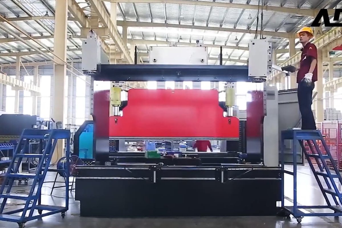
Full-machine lifting typically occurs during equipment installation, plant relocation, or layout adjustments. This is considered the “deep end” of industrial rigging—not only due to the machine’s massive weight but also its peculiar geometry: tall, narrow, and extremely top-heavy.
This section breaks down the two most common methods—overhead crane lifting and forklift handling. Regardless of approach, one rule governs all: control the center of gravity and prevent torsion.
3.1 Method One: Overhead Crane Lifting Procedure
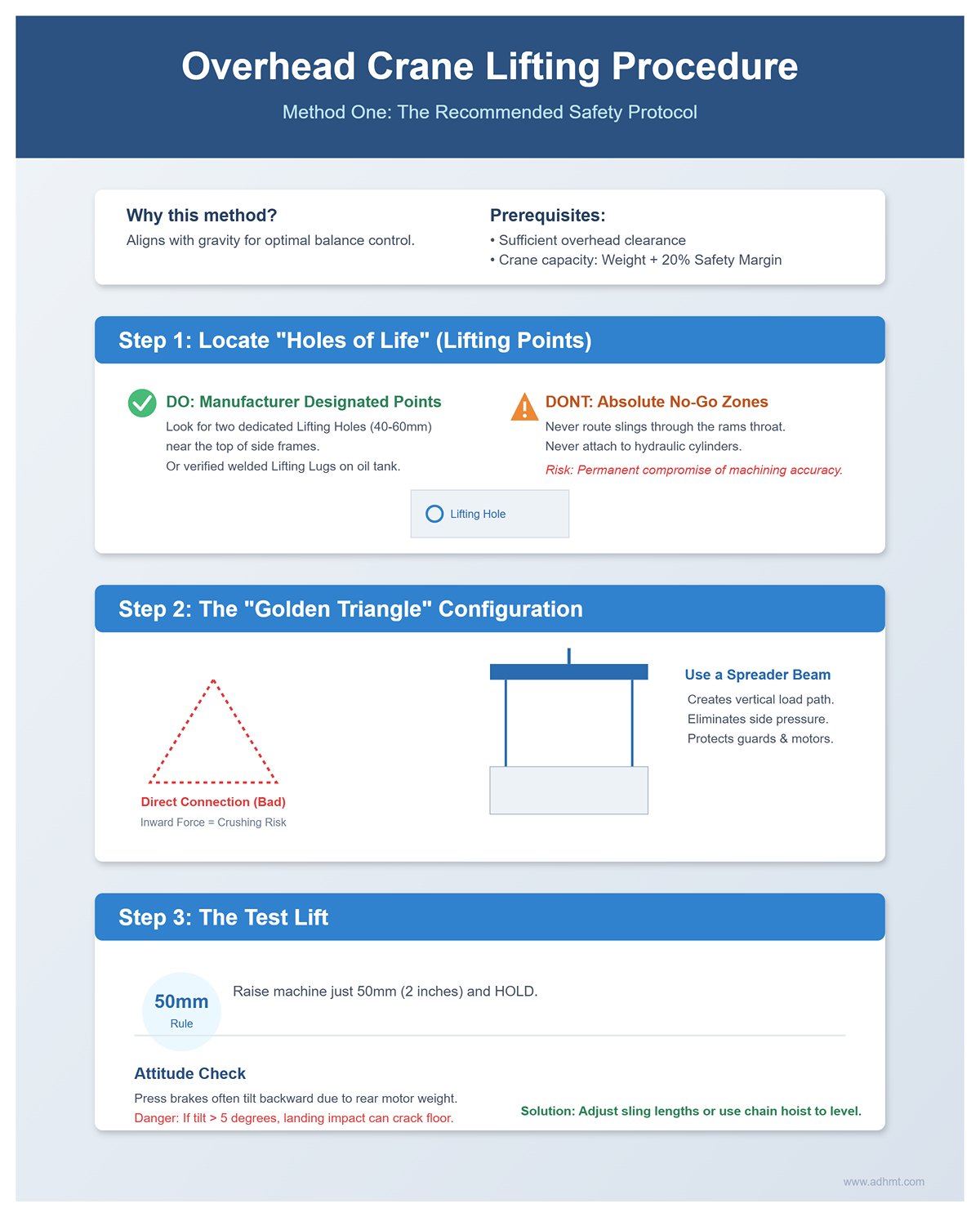
This is the recommended method since suspended lifting naturally aligns with gravity’s vertical axis, providing optimal balance control. However, your facility must have sufficient overhead clearance, and the crane’s rated capacity should include at least a 20% safety margin.
Step 1: Locate the “Holes of Life” (Lifting Points) Never rely on intuition by hooking onto beams or seemingly sturdy frame sections!
- Manufacturer-Designated Points: Leading press brake manufacturers (such as Amada, Trumpf, Accurl) typically provide two dedicated Lifting Holes (40–60mm diameter) near the top of each side frame, or weld Lifting Lugs on the oil tank verified through non-destructive testing.
- Absolute No-Go Zones: Never route slings through the ram’s throat or attach directly to hydraulic cylinders. These are precision motion components, and even microscopic deformation—imperceptible to the eye—can permanently compromise machining accuracy.
Step 2: The “Golden Triangle” Sling Configuration This is one of the most common mistakes made by beginners—connecting two wire ropes directly between the crane hook and the machine’s sides, forming a simple inverted triangle.
- Crushing Risk: When the sling angle drops below 60 degrees, enormous horizontal forces are generated. These inward forces can easily crush the machine’s top sheet-metal guards, motor fans, or even sensitive hydraulic lines.
- Essential Equipment – The Spreader Beam: A professional lifting setup must include a rigid spreader beam. The beam should be slightly longer than the machine’s width, forming a vertical load path: “Overhead crane hook → spreader beam → two vertical wire ropes/chains → shackles → lifting holes on the machine frame.” This design eliminates side pressure and significantly improves stability during the lift.
Step 3: The Test Lift Lifting is never a “one-click” operation—it’s a careful process of incremental testing and adjustment.
- The 50mm Rule: Raise the machine just 50mm (2 inches) off the ground and hold it there.
- Attitude Check: Observe the machine’s balance. Because the backgauge system and main motor are usually located at the rear, press brakes often tilt backward. If the tilt exceeds 5 degrees, one side of the machine’s base will bear several tons of impact when landing, potentially cracking the floor or damaging the feet. Lower the machine, then adjust sling lengths or use a chain hoist to fine-tune balance until the frame is level.
3.2 Method Two: Heavy Forklift Handling Process
If the facility lacks overhead crane capacity or unloading must occur outdoors, a forklift is the only alternative. However, this is a high-risk zone for tip-over accidents, as the press brake’s high center of gravity pushes a forklift’s stability to its limits.
Step 1: Capacity and Load Center Calculation This is a classic trap: a 10-ton press brake cannot usually be lifted safely by a forklift rated at 10 tons—it may even cause the forklift’s rear wheels to lift off the ground.
- The De-rating Rule: By leverage principles, every 25mm (1 inch) increase in load center reduces the forklift’s capacity by roughly 3–5%. To safely lift a 10-ton press brake, you’ll typically need a 15-ton or even 20-ton heavy-duty forklift.
Step 2: Fork Entry and Positioning
- Rear Approach: Most manufacturers recommend approaching from the rear, as the back side is flatter and closer to the machine’s center of gravity, reducing the lever arm. If front access is unavoidable, avoid contact with the foot pedal, material support arms, and front electrical cabinet.
- Soft Isolation: Place hardwood blocks or industrial rubber pads between the forks and the bottom of the machine bed. Metal-to-metal contact is strictly prohibited—not only to protect the paint but also to increase friction and prevent slippage during sudden stops.
- Rigid Locking: This is critical! Use high-strength ratchet straps or chains to tightly secure the machine to the forklift’s backrest, creating a single rigid structure.
Step 3: The “Low-Flight” Principle
- Maximum Height: During transport, keep the machine’s clearance under 100mm (4 inches). Lifting it higher is extremely dangerous—especially when turning, as centrifugal force increases exponentially with height.
- Blind Operation: The tall body of the press brake completely blocks forward visibility. The forklift operator must drive in reverse, guided by a trained spotter walking alongside. Solo, blind driving is strictly prohibited.
IV. Practical Exercise B – Safe Daily Tooling Changeover and Lifting
Don’t be deceived by how “small” the tooling appears. In workplace accident statistics, press brake tooling causes injuries far more often than full-machine handling. A standard 835mm upper die can weigh 20–30kg—right in the ergonomic “danger zone.” It looks manageable by hand, but a single slip from a sweaty grip can send its hardened edge crashing down with enough force to shatter bones or sever tendons.
This section outlines a tooling changeover procedure as precise and error-free as an F1 pit stop—eliminating everyday risks through disciplined, standardized steps.
4.1 Preparation Stage: Energy Isolation and Workspace Cleaning
Before your fingers touch the tooling steel, the machine must be “locked out” both physically and logically. Attempting a tool change under pressure is gambling with your life.
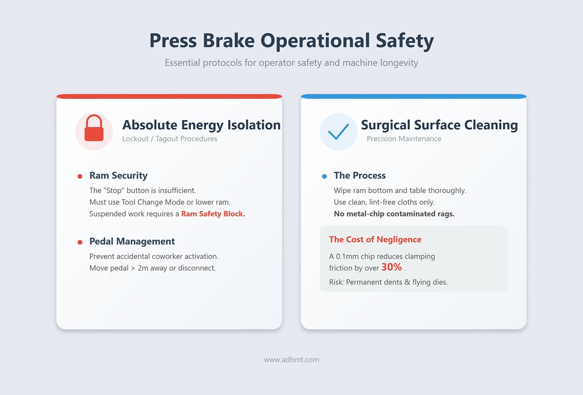
- Action 1: Absolute Energy Isolation (LOTO – Lockout/Tagout)
- Ram Physically Locked: Simply pressing the “Stop” button is not enough. If the press brake lacks a dedicated “Tool Change Mode” (which locks the ram at top dead center and releases hydraulic pressure), you must manually lower the ram to bottom dead center. If work must be performed with the ram suspended, it is mandatory to insert an electrically interlocked Ram Safety Block. This prevents the deadly “guillotine effect” that can occur if seals fail or a hydraulic line bursts.
- Prevent Accidental Activation: Move the foot pedal at least two meters away from the work area or disconnect its plug entirely. Many finger-crushing accidents happen when a coworker unknowingly steps on the pedal.
- Action 2: Surgical-Level Surface Cleaning
- Micron-Level Risks: Thoroughly wipe the ram bottom and table surface with a clean, lint-free cloth. Never use a rag containing metal chips.
- Physical Consequences: A single 0.1mm metal chip trapped between the die and clamping beam can permanently dent expensive tooling and reduce clamping friction by over 30%. During bending, inadequate clamping force could send the die flying like shrapnel.
4.2 Core Procedure: Tool Lifting and Installation SOP
Manual handling of heavy or irregular dies weighing over 25kg is strictly prohibited. Follow the standardized operating procedure (SOP) below:
- Step 1: Identify the Tool Loading Style (Loading Style Protocol)
- Side-Loading: This is the traditional but higher-risk approach. The operator places the mold on the side-mounted bracket of the slider and pushes it in horizontally. Warning: Never place your fingers at either end of the mold during insertion. Always press on the front face of the mold to avoid crushing or severing your fingers at the end of the slider.
- Vertical Loading: Modern precision molds are typically equipped with Safety-Click or Safety-Tang mechanisms. This design allows the mold to be inserted vertically upward into the clamping groove. A crisp “click” sound indicates that the mechanical interlock is engaged—meaning that even without hydraulic clamping pressure, the mold will remain securely in place and not fall.
- Step 2: Selecting and Attaching the Lifting Device
- No Rough Handling: Never use ordinary steel cables to tie up the mold. Mold surfaces are smooth and extremely hard, making steel cables prone to slipping off and damaging precision surfaces.
- Use Specialized Tools: Always use dedicated Tooling Grippers. These clamps typically feature a scissor-action design or polyurethane friction pads, which leverage the mold’s own weight to generate self-locking clamping force.
- Balance Principle: For molds longer than one meter, single-point lifting will cause pendulum-like swinging, making alignment nearly impossible. Always use dual-point lifting or a spreader beam, positioning lifting points at the 1/4 and 3/4 positions along the mold’s length to ensure it remains level and aligns precisely with the slot.
- Step 3: Pre-Clamping and Alignment (Pre-Clamping & Seating)
- Golden Rule: After the mold is seated in the slot, do not immediately tighten it fully. First, activate the Pre-Clamp mode (half lock).
- Forced Seating: Perform one slow, low-tonnage dry cycle to ensure alignment. Allow the upper die to descend gently onto the lower die (with no sheet metal in between), using the lower die’s V-groove to force the upper die into true alignment. Once the upper and lower dies are fully seated, proceed with the Final Locking. Skipping this step is the leading cause of bending angle deviations and tooling damage.
4.3 Pro Tips: Handling Segmented and Long Tooling
Experience shows that the biggest challenge often lies not in handling a single heavy item, but in managing multiple interconnected components.
- Preventing the “Domino Effect” with Segmented Tooling
- When installing segmented tooling or ear pieces for box bending, it’s very easy for pieces to topple in a chain reaction.
- Strategy: Always follow a single installation direction—either left to right or right to left. After installing each piece, immediately lock it in place (or confirm that the Safety Hook is engaged). Never leave multiple segments standing loosely on the slider; once the first one tips, the entire set can collapse dangerously.
- Two-Person Rule for Manual Handling of Long Tooling
- When manually handling an 835mm standard section approaching the upper limit of human capacity, two operators must work together.
- Strict Safety Zone: Hands should only support the ends or back of the mold. Never insert fingers beneath the V-groove or sharp edge—these are absolute “no-finger zones.”
- Voice Coordination: Designate one person as the leader to give clear verbal commands (“Ready—Lift,” “Move,” “Ready—Set Down”). Silent coordination often leads to uneven force distribution, increasing the risk of back strain or dropping the mold.
V. Advanced Techniques: Efficiency and Ergonomics
Once the fundamental safety principles of lifting are mastered, the next focus is on efficiency and ergonomics. In a modern sheet metal workshop, fatigue is an invisible safety hazard, and inefficiency is a silent profit drain.
Prolonged manual handling not only exhausts operators and reduces concentration, but also significantly raises the risk of accidents. This chapter explores both technical upgrades and management approaches to help you achieve seamless, human-machine synergy for optimal performance.
5.1 Application of Quick-Change Systems
If your workshop still relies on manually tightening mold screws with a hex key, you’re not just wasting valuable production time—you’re also accumulating hidden safety risks. Quick-Change Clamping Systems are no longer a luxury; they are the new standard in modern bending operations.
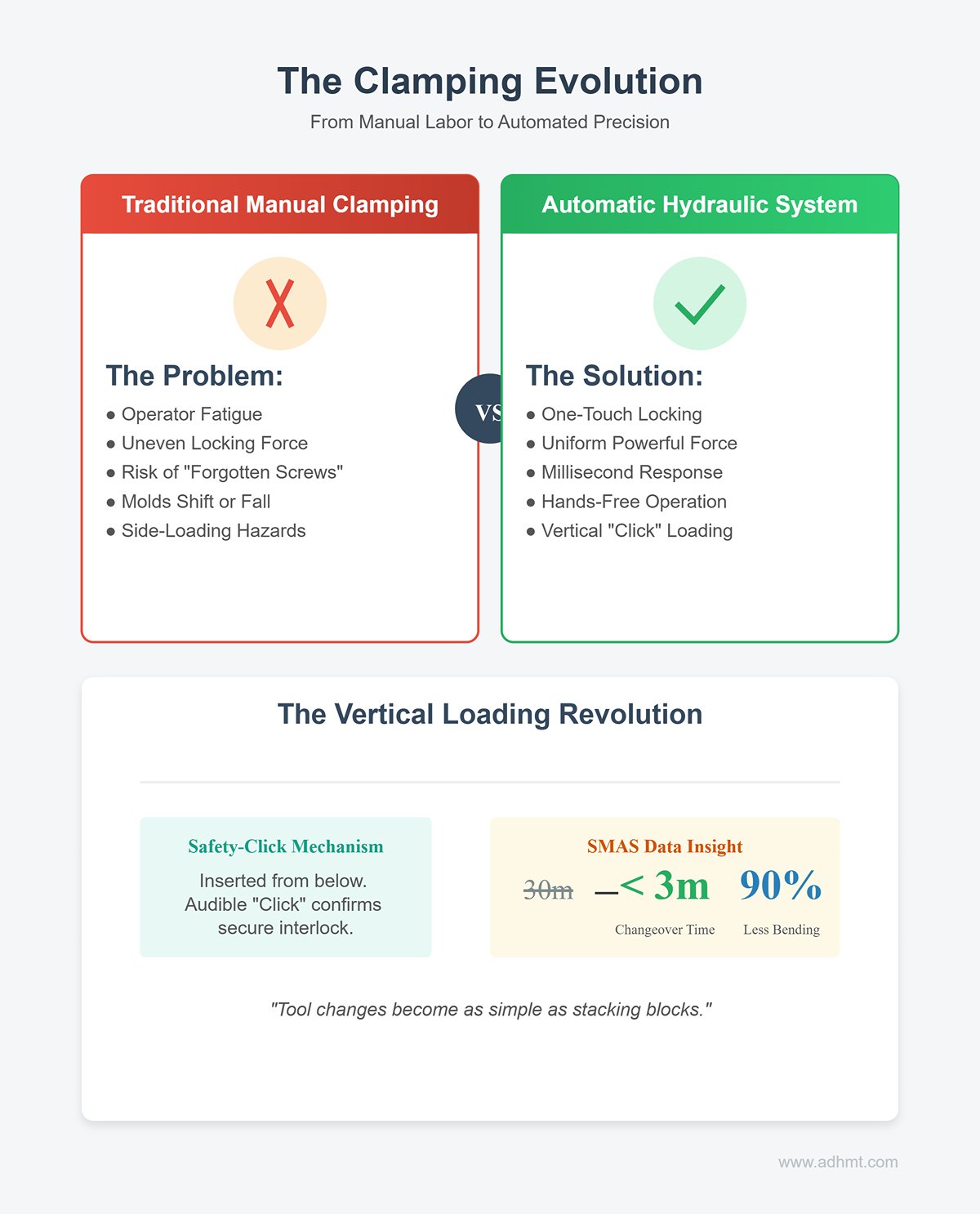
- From Muscle Work to One-Touch Locking: Traditional manual clamping can easily result in uneven locking force due to operator fatigue, causing molds to shift or fall under heavy load. Hydraulic or pneumatic automatic clamping systems apply uniform, powerful clamping force across the entire mold set at the push of a button—within milliseconds. This eliminates human error such as “forgotten screws” and frees the operator’s hands completely.
- The Vertical Loading Revolution: Paired with quick-clamp systems are new molds featuring Safety-Click mechanisms, allowing them to be vertically inserted from below into the clamping groove. The crisp “click” confirms that the mechanical interlock is fully engaged.
- Key Advantage: This design completely eliminates the hazards of side-loading. Operators no longer need to worry about molds slipping off from the slider side—tool changes become standardized, safe, and as simple as stacking blocks.
- Data Insight: According to SMAS (Sheet Metal Association) statistics, automatic clamping with vertical loading reduces average tool change time from 30 minutes to under 3 minutes, while cutting bending and lifting motions by 90%.
5.2 Intelligent Assist Devices
In press brake operations, there’s an awkward “weight gap” between 15kg and 40kg—too heavy for manual lifting, too light to justify an overhead crane. The solution lies in Intelligent Assist Devices (IADs).
- Zero-Gravity Arms: Introducing devices such as the Gorbel Easy Arm or similar servo-assisted arms represents the ultimate ergonomic upgrade. These systems feature built-in force sensors that detect subtle finger pressure and instantly provide proportional lifting assistance.
- Floating Experience: With IAD support, even a 50kg mold feels weightless—almost as if it’s floating in space. This allows operators to focus entirely on precise alignment rather than physical exertion, eliminating muscle tremors and associated safety risks.
- Height Strategy for Mobile Tool Carts: Never underestimate the value of this small cart. A well-designed tool cart must allow for height-level docking with the press brake table.
- Operational Details: Adjust the shelf height of the cart so it is perfectly level with the lower die table of the press brake. This way, the operator only needs to perform a horizontal sliding motion rather than a vertical lift. This simple adjustment can prevent up to 80% of lower back strain injuries.
- Magnetic Lifters and Vacuum Hoists: When handling large sheet materials, magnetic handles (such as Magswitch) or vacuum lifters are essential. They allow operators to control the flipping or positioning of sheets from a safe distance, preventing cuts from sharp edges or pinch injuries in the bending zone.
5.3 Team Coordination and Communication Standardization
In a workshop where noise levels exceed 80 decibels, shouting is both ineffective and hazardous. For multi-person lifting operations on large press brakes, it’s critical to establish a tactical hand signal system that eliminates the need for verbal communication.
- One Voice Policy — The Iron Rule: Every lifting operation must have one—and only one—designated signal person. The crane or forklift operator should take commands exclusively from this individual. Multiple voices giving orders is a recipe for disaster.
- Standard Rigging Signals: Spontaneous gestures are prohibited. All team members must be proficient in OSHA/ASME-compliant standard hand signals:
- Hoist Up: Point your index finger upward and move it in a circular motion.
- Lower Down: Extend your palm downward and move it up and down.
- Emergency Stop: Extend both arms horizontally to the sides and wave them rapidly.
Standardized signals cut through the noise barrier, ensuring that commands are instantly understood and executed—even in emergencies.
- The One-Second Eye Contact Rule: Before pressing the lift or move button, the rigger and operator must make direct eye contact or exchange a thumbs-up signal. This one-second pause confirms that both have moved to a safe zone and that no hands are on the load. It’s the final—and most effective—line of defense against crush injuries.
VI. Crisis Response and Case Warnings
In industrial safety, Heinrich’s Law looms large: behind every serious injury lie 29 minor injuries and 300 near misses. Waiting until disaster strikes to open the emergency manual is too late. This chapter goes beyond standard procedures, dissecting real-life incidents with forensic precision to build both psychological awareness and physical safeguards.
6.1 In-Depth Analysis of Typical Accidents
Let’s confront two real-life nightmares from sheet metal workshops. The aim isn’t to instill fear, but to expose the deadly oversights hidden beneath so-called “experience.”
Case 1: The 290-Pound “Flying Disc of Death” — Catapult Triggered by Improper Support
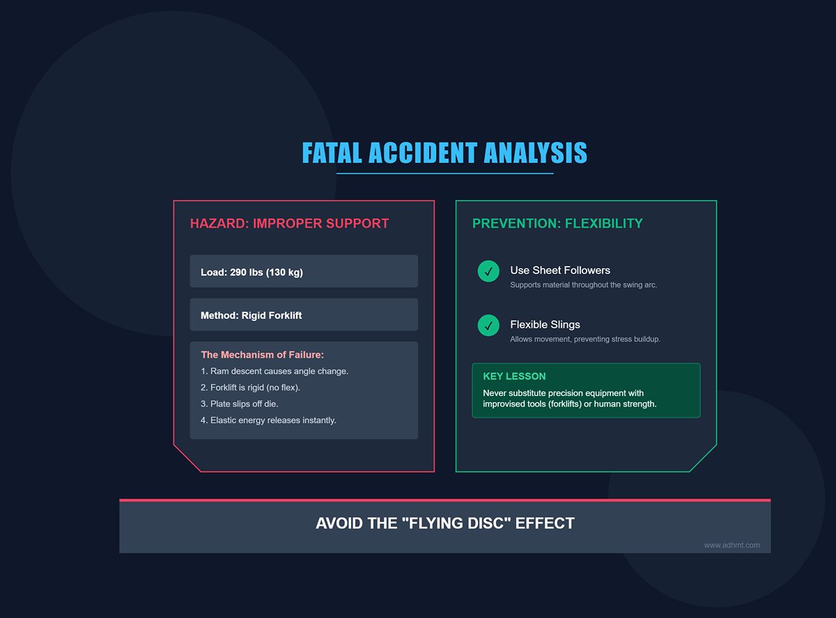
- Incident Replay: A 39-year-old experienced operator was bending a large steel plate weighing 290 pounds (about 130 kg). To save time, he skipped using a flexible sling or sheet-following arm, instead supporting the plate rigidly with a forklift while standing to the front side to make fine adjustments by hand. As the ram descended, the plate edge slipped off the lower die. The resulting lever effect and rebound force catapulted the plate upward like a flying disc, striking the operator’s chest and head, killing him instantly.
- Key Lessons:
- The Fatal “Human Support” Trap: Never use your body—or a forklift—as a precision support device. Forklifts have slight hydraulic drift and no adaptive flexibility to accommodate angle changes during bending.
- The Deadly “Whip Effect”: During large-sheet bending, the outer edge of the plate swings sharply upward as the ram descends. Without a sheet follower or a properly tensioned suspension system to release stress, the stored elastic energy can unleash with bone-shattering force.
Case 2: The “Shotgun Effect” of Die Fracture — Overload and Brittle Failure
- Incident Replay: During a high-strength steel (Hardox) bending operation, the operator violated safety protocols by using a punch with an excessively small radius to achieve a tighter bend. The press load was increased far beyond the die’s rated limit—from 60 tons/m to 100 tons/m. With a thunderous crack, the hardened die fractured brittlely, sending shards flying like shotgun pellets. One fragment pierced the operator’s polycarbonate goggles, causing permanent blindness.
- Key Lessons:
- Lifting Hazards Aren’t the Only Risk: Even with flawless die installation, incorrect parameter settings (overloading) can turn the press into a ticking time bomb.
- Fragment Protection and Positioning: Operators must strictly follow the “side stance” rule—never place your head directly in front of the die. Hardened steel is extremely hard but also brittle; when it fractures, fragments radiate outward, and the front zone becomes a lethal arc.
6.2 Emergency Response Protocols
When all preventive measures fail and disaster strikes, the first 10 minutes determine whether the outcome is survivable or irreversible. The following are survival protocols for three critical scenarios.
Scenario A: Equipment Tipping During Lifting (The Tipping Point)
This is the most terrifying moment during machine relocation—the press brake suddenly loses balance mid-air and begins to tilt.
- The Trap of Instinct: Most people’s first reaction is to rush forward and push the machine upright. This is absolutely forbidden and suicidal behavior! Human strength is insignificant against a 10-ton machine—it will only result in being crushed.
- Correct Evacuation and Damage Control:
- Trigger the “Clear the Zone” Command: The signal person must immediately issue the loudest possible evacuation warning, clearing everyone within 1.5 times the machine’s height.
- Down Only: If the machine is still suspended, the operator should slowly lower the hook to bring it to the ground—even if unevenly. Never attempt to pull up quickly to correct the tilt! Sudden lifting creates massive dynamic loads that can snap cables and cause total free-fall.
Scenario B: Crush Injury
If a hand or limb becomes trapped under a die or ram, survival often depends on a counterintuitive medical principle.
- The Golden 15-Minute Rule:
- < 15 minutes: If the limb has been trapped for less than 15 minutes, immediately operate the machine to lift the slider or remove the heavy object to release the limb. Then, stop the bleeding and apply proper bandaging.
- > 15 minutes (Red Alert): If the limb has been pinned for more than 15 minutes, non-medical personnel must never attempt to remove the heavy object!
- Underlying principle: This rule exists to prevent Crush Syndrome. Prolonged compression causes the damaged tissue to release large amounts of potassium ions and myoglobin, which are toxic to the body. If the object is suddenly removed and blood flow is restored, these toxins can surge into the heart and kidneys, potentially leading to cardiac arrest or acute renal failure. In such cases, maintain the current state and wait for professional rescuers equipped with tourniquets and alkalizing agents to handle the situation.
Scenario C: Tooling Stuck Mid-Air
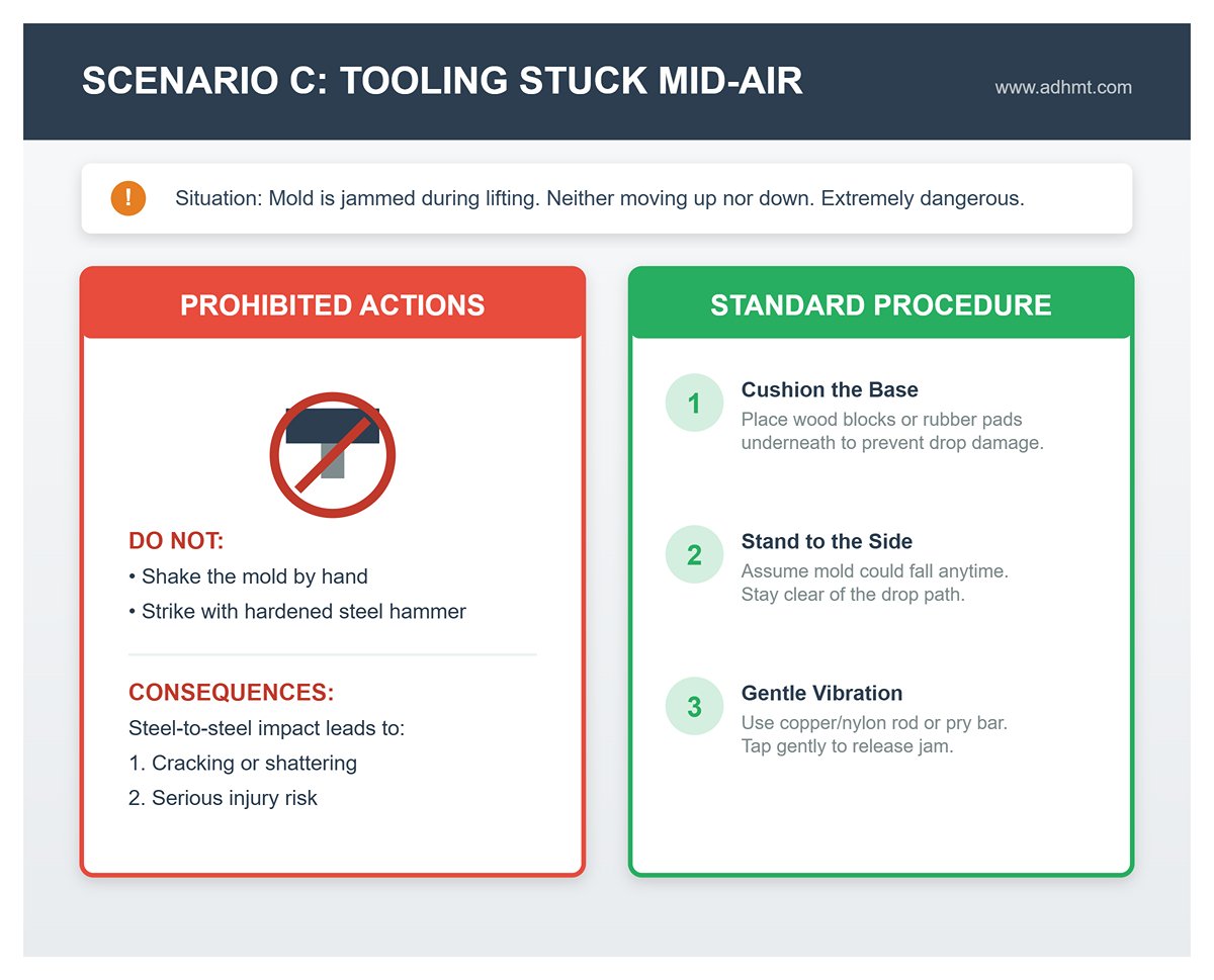
When a mold becomes jammed during lifting or disassembly—neither moving up nor down—it creates an extremely awkward and dangerous situation.
- Prohibited actions: Never try to shake it by hand or strike it forcefully with a hardened steel hammer. Steel-to-steel impact can cause the mold to crack or shatter, posing a serious injury risk.
- Standard release procedure:
- Stand to the side: Always assume the mold could fall at any moment. Position yourself to the side of its potential drop path.
- Gentle vibration: Use a copper or nylon rod as an intermediary tool to tap and vibrate the mold, or use the flat end of a pry bar.
- Cushion the base: Before any attempt to free the mold, place wooden blocks or thick rubber pads underneath to cushion against sudden drops and prevent damage or rebound injuries.
VII. Conclusion
How to lift a press brake or its tooling is not a test of strength, but a discipline of physics. By replacing manual guesswork with the "3C" Verification System (Calculation, Condition, Clearance) and adopting strict "Safety-Click" and "15-Minute Rule" protocols, you transform high-risk lifts into predictable science. Investing in dedicated spreaders, magnetic grippers, and quick-change systems does not just prevent crushed fingers—it builds a factory culture where speed is fueled by safety, not luck.
Stop relying on luck. Equip your shop with press brake solutions engineered for zero-accident efficiency. ADH Machine Tool, with 20+ years of expertise, offers CNC press brakes and tooling systems designed for ergonomic safety and rapid changeovers. To explore customized solutions for your production line or consult technical experts, contact us.


