How to make a press brake die is a skill rooted in precision engineering, material science, and hands-on manufacturing expertise. This process starts with detailed design considerations, ensuring the die matches the specific bending angles and radii required.
From selecting the right steel to rigorous machining, heat treatment, and quality control, every step is critical to creating durable and accurate press brake tooling. In this guide, we will walk through these essential stages, providing expert insight into producing a high-quality press brake die that meets both performance and longevity demands.
I. Strategic Decision-Making and Feasibility Assessment: Why Manufacture Instead of Buy?
Before any machining begins, the most critical step isn’t choosing a cutting tool—it’s conducting a cold, hard cost-benefit analysis. Manufacturing press brake dies isn’t just a technical challenge; it’s a business decision.
Many workshop managers and experienced machinists fall into the trap of thinking “as long as we have a milling machine, we can make it,” while overlooking hidden and opportunity costs. This chapter introduces quantitative metrics to help you determine when to fire up your CNC and when to place an order instead.
1.1 DIY vs. Buy Decision Matrix
Essentially, deciding whether to make your own dies is about balancing time assets against capital expenditure. Below is a decision matrix based on real workshop scenarios to help assess whether your project qualifies for the “DIY advantage.”
| Evaluation Dimension | Strongly Recommend DIY | Recommend Purchase | Core Decision Logic |
|---|---|---|---|
| Uniqueness | Custom or non-standard: specialized radii, offset goosenecks, or multi-bend forming dies unavailable as standard products. | Standard: common V-openings (88°/90°), straight punches, or sharp-angle tools. | Standard dies are mass-produced industrial items often priced lower than your combined material and labor cost. Only non-standard work truly delivers high DIY value. |
| Lead Time | Extremely urgent (24–48 hrs): production stops without the die. | Normal (1–2 weeks): the schedule has buffer time. | Supply chains can’t beat a workshop’s forklift. If your downtime costs run hundreds of dollars per hour, in-house manufacturing is the only way to stop the bleeding. |
| Material Hardness | Medium/low hardness or temporary use: suitable for aluminum or mild steel, unquenched 4140/P20 steel is adequate. | High hardness/long life: requires full hardening to HRC 50+ and precision grinding. | Most small to mid-sized shops lack large heat-treatment and long-bed grinders. DIY high-hardness long dies risk distortion and poor straightness, costing more in the end. |
| Length Limitation | Segmented or short dies (<500 mm): easily handled on standard CNC mills. | Full-length dies (>2000 mm): require large gantry mills or planers. | Machine travel is a hard limit. Force-fitting long dies through sectioned machining makes maintaining coaxiality and V-slot parallelism nearly impossible, hurting bend accuracy. |
| Cost Structure | Material on hand: leftover tool steel or scrap dies available for repurposing. | Full material purchase: must order expensive tool steel blanks. | Leveraging “sunk costs” (scrap stock) can significantly boost your DIY ROI. |
Expert Insight: Don’t just count material costs! Always include your machine hourly rate and programming/operator labor. If making a standard V8 die costs you $200 in total while the market price is $150, you’re burning profit—not saving it.
1.2 Choosing the Right Die Type for the Application
Once you decide to make your own die, the next step is to select the proper type for the material and operation. A poor choice can lead to cracked dies or scrapped workpieces.
A. Straight / T-Type Lower Dies
- Application: The easiest type to fabricate. Suitable for 90° bends and the pre-hem operation before flattening.
- Design Advantage: Simple structure—typically just a block milled with a V-groove.
- DIY Recommendation: Ideal as a first project. Its symmetrical design makes heat-treatment distortion relatively easy to control.
B. Gooseneck Punches
- Application: Used for bending U-channels, deep boxes, or parts with return flanges that interfere with standard punches.
- Manufacturing Difficulty: High.
- Risk: The gooseneck area experiences severe stress concentration. With improper material selection or insufficient tempering after heat treatment, the punch can snap at the neck under high load—posing serious safety hazards.
- Expert Warning: Unless you have finite element analysis (FEA) capability to validate strength, exercise caution when attempting to make deep-throat gooseneck punches yourself.
C. Urethane / Non-Marking Dies
- Application: For stainless mirror finishes, aluminum, or other materials where surface marring is unacceptable.
- DIY Benefit: Exceptionally high.
- Operation: This is the most cost-effective DIY category. You only need to machine a simple metal retainer and insert a high-durometer urethane rod (typically 80A–95A).
- Advantages: No heat treatment or precision grinding required. Extremely low cost with immediate, professional results.
D. Offset / Forming Dies
- Application: For Z-bends (joggle/offset), curling, or rib forming operations.
- Decision Logic: These dies often require multiple trials and fine-tuning. Buying custom dies is costly and slow to modify. DIY fabrication dramatically shortens R&D validation cycles, making it an excellent opportunity for engineers to demonstrate technical expertise.

II. Core Engineering Design: Parametric Modeling and Structural Verification
Designing a press brake die is far more than drawing a “V” in CAD. If you skip the mechanical analysis and rely solely on intuition, two outcomes are likely: either the die deforms permanently during first-use testing, or it fractures under load—potentially causing injury. This chapter builds a safe, efficient engineering model from both mathematical and physical perspectives.
2.1 Mathematical Models for Key Geometric Parameters
In air bending—the most common scenario for homemade dies—geometry determines forming accuracy and springback control. You can’t just design for the angle you want; you must design for the compensated angle.
Golden Rule and Adjustment for V-Opening Width (V):
The empirical rule V = 8t (t = sheet thickness) is only a starting point.
- Thin Sheets (t < 2.5 mm): Use V = 6t for a smaller bend radius, though this increases tonnage requirements.
- Medium to thick plates (t > 10 mm): Use a die opening of V = 10t or 12t to prevent the sheet from cracking.
- Natural bend radius (Ir) prediction model: This serves as a key reference for designing the punch radius. In air bending, the inner bend radius naturally formed in the sheet is roughly 16% of the V-die opening: Ir ≈ V/6.
Design insight: If you’ve made a lower die with a 50 mm V-opening, the sheet will naturally form an inner radius of about 8.3 mm, no matter how sharp your punch is. Forcing a punch with a 1 mm tip radius will only cut into the material, leaving indentations rather than producing a proper bend.
Springback compensation angle (Δα):
Never design a 90° V-groove to produce a 90° bend — metal has elastic memory.
- Mild steel: Expect about 1°–2° of springback. The V-groove should be designed at approximately 88°.
- Stainless steel (SS304/316): Springback ranges from 2°–5°. Recommended groove angle: 85°–86°.
- Aluminum alloy (Al 5052): Typical springback is around 1.5°.
- Geometric compensation strategy: When designing the die profile, always reserve space for over-bending. For general-purpose dies, 85° or 88° angles are smarter engineering choices than 90°, as they can accommodate bends from 90° to 160° simply by adjusting the pressing depth.
Minimum flange length (b_min) check:
To prevent the workpiece from slipping into the V-opening and being scrapped, always verify the minimum flange length: b_min = 0.7 × V. For instance, if your design calls for a 10 mm flange, your die opening must not exceed 14 mm.
2.2 Load Limits and Safe Tonnage Calculation (The Safety Core)
This is the most critical stage of the entire fabrication process. Homemade dies often lack official nameplate data, leading operators to apply force blindly. As the designer, you must determine the die’s physical threshold.
- Air bending force formula: First, calculate the reaction force exerted by the sheet on the die:
F = (1.42 × UTS × L × t²) / V.
- The dangerous square law: Note the $t^2$ term in the formula — doubling the sheet thickness increases the required force by a factor of four. This is the number one cause of die failure in homemade setups.
- Die compressive strength limit: Calculating the bending force isn’t enough; you must also confirm whether the die material can withstand it. The die’s capacity depends on the shoulder contact area and the yield strength of the steel.
- Typical 42CrMo (4140) pre-hardened steel limit: Safe load is roughly 100 tons per meter (Ton/m).
- Standard A3 / No.45 steel (non-heat-treated): Safe load is only about 30–40 tons per meter.
- Design red line: If your calculated bending force $F$ exceeds the die material’s load capacity per unit length, you have two options: widen the V-opening (reduces force) or switch to higher-grade tool steel with proper heat treatment (increases resistance).
- Safety factor (K): Because homemade dies may have uneven heat treatment or microcracks, never design at full capacity. Always satisfy F_design ≥ 1.5 × F_working. For example, if your process requires 60 tons of pressure, the die structure must be rated to at least 90 tons.
2.3 Interface and Tolerance Design
A die must not only be strong but also precise. This section determines whether the die can be mounted smoothly onto the press brake and whether the bent parts will come out perfectly straight.
- Tang standardization: Never machine the tang by eye or memory. Measure your press brake’s actual interface type (Amada/Promecam, American, or Wila style).
- Tolerance requirements: The tang’s thickness and height should be controlled within +0.00mm / -0.05mm. Too thick, and it won’t fit; too thin, and it will tilt under clamping pressure, causing uneven loading.
- Fail-safe design: For segmented dies, always include a safety tang or hook to prevent the die from falling if the clamp is released — your last line of defense against crushed fingers or damaged equipment.
- Parallelism: The core accuracy metric for a press brake die is the parallelism between the V-bottom line and the die base.
- Standard: Across the full length, parallelism error should be less than 0.02mm per meter.
- Consequence: If parallelism deviates by 0.1mm, a thin sheet bend may result in one end being 90° while the other is 92°. This kind of taper error becomes a nightmare during subsequent welding — nearly impossible to fix.
- Relief and interference check: When designing gooseneck punches or deep-channel dies, always simulate the full bending process in CAD.
- Springback clearance: The punch’s sidewalls shouldn’t be perfectly straight; they should include at least a 15° relief angle to prevent the workpiece from wrapping around the die after forming a U-shape.
- Root radius stress relief: Avoid designing a perfectly sharp corner at the bottom of the V-groove. Provide a fillet of $R0.5mm$–$R1.0mm$. This reduces stress concentration, prevents cracking, and gives space for scale or dust generated during bending, preventing surface damage to the workpiece.
III. The Material Science Behind Die Longevity
If CNC machining gives a die its form, material science gives it its soul. Under the immense tonnage of a press brake, the wrong material choice doesn’t just shorten tool life — it can trigger shrapnel-like accidents. For DIY die makers, understanding materials isn’t just about reading supplier data sheets; it’s about mastering the trade-off between cost, machinability, and safety margin.
3.1 In-depth Comparison of Die Steel Performance
Don’t get distracted by the dizzying array of steel grades. For press brake dies, only three properties truly matter: compressive yield strength (to prevent collapse), surface wear resistance (to prevent scratching), and core toughness (to prevent cracking).
Below are four mainstream material options for DIY die fabrication, each suited to a distinct “battlefield.”
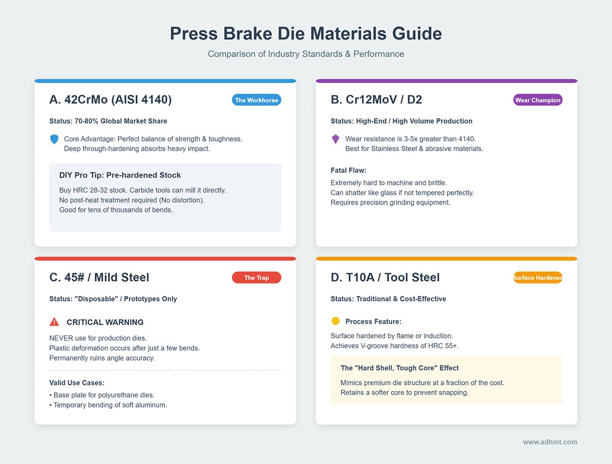
A. 42CrMo (AISI 4140) — The Industry Workhorse
- Status: The “Swiss Army knife” of press brake dies. Roughly 70–80% of standard dies worldwide are made from 42CrMo.
- Core Advantage: Exceptional balance of strength and toughness. Its high hardenability allows deep through-hardening while retaining enough toughness to absorb impact.
- DIY Shortcut (Pro Tip): Buy pre-hardened 4140 stock (HRC 28–32).
- Why: At this hardness, carbide tools can mill it directly, producing a ready-to-use part with no post heat treatment required. This eliminates the biggest barrier for DIYers—heat-treat distortion and outsourcing. Although it doesn’t last as long as fully hardened steel, it easily handles tens of thousands of bends.
B. Cr12MoV / D2 (AISI D2) — The Wear-Resistance Champion
- Status: A high-end choice for stainless steel, high-strength materials, or large-volume production.
- Core Advantage: A high-carbon, high-chromium cold-work tool steel with wear resistance 3–5 times greater than 4140.
- Fatal Flaw: Extremely difficult to machine and brittle. If your heat treatment isn’t perfectly tempered, D2 dies under heavy load can shatter like glass.
- Best For: Advanced fabricators with precision grinding equipment and professional heat-treatment capability.
C. 45# Steel / A3 Steel (Mild Steel) — The “Disposable” Temptation
- Status: Suitable only for prototypes or short-term emergency use.
- Critical Warning: Never use mild steel for production dies. Its yield strength is far too low—under pressure at the V-groove, plastic deformation occurs after just a few bends, permanently ruining angle accuracy.
- Only Use Case: As a base plate for polyurethane dies (retainer) or temporary dies for bending aluminum sheets.
D. T10A / Tool Steel — Ideal for Surface Hardening
- Status: Traditional yet effective.
- Process Feature: Can be surface-hardened by flame or high-frequency induction, achieving a V-groove hardness of HRC 55+ while retaining a softer core. This mimics the “hard shell, tough core” structure of premium dies at a fraction of the cost.
3.2 The Art of Balancing Hardness and Toughness
In mold failure analysis, we face a timeless paradox: the harder the material, the better its wear resistance, but the greater its brittleness; the tougher the material, the better it resists fracture, but the easier it deforms and wears.
For press brake dies, the logic of “better to crack than deform” is completely wrong. In reality, our goal is “better to wear than to explode.”
A. The Catastrophic Mistake of Full Hardening
Many beginners believe that harder is always better, quenching the entire die to HRC 58–60.
- Risk Scenario: When bending forces slightly exceed rated capacity or sheet thickness variations cause local overload, an over-hardened die won’t yield—it will suffer brittle fracture. Under tens of tons of pressure, fragments can eject like bullets.
- Safety Threshold: For fully heat-treated dies, HRC 47–52 is the universal upper safety limit. Beyond this, you must trade overall hardness for surface treatment techniques.
B. The Ideal Hardness Gradient Model
Top-tier die manufacturers (e.g., Wila, Trumpf) don’t use uniform hardness—they engineer hardness gradients:
Wear Zone:
- Location: The upper die tip and lower die shoulder radius.
- Target Hardness: HRC 52–56.
- Method: Laser or high-frequency induction hardening to a depth of 2–4 mm. This hard “skin” resists intense friction from sheet sliding.
Body Core:
- Location: The main body and clamping shank.
- Target Hardness: HRC 28–32 (tempered state).
- Purpose: Provides resilience against cyclical loads and ensures that in case of accidental impact (such as sheet overlap), the die deforms rather than fractures.
C. Practical Advice for DIY Fabricators
If complex gradient heat treatment isn’t an option, follow the “Safety First” golden rule:
- Use pre-hardened 4140 as the base material.
- After machining, apply simple flame surface hardening only to the upper die tip and lower die V-radius, followed by low-temperature tempering.
- Although this “low-tech” approach lacks the precision of laser hardening, it delivers about 80% of professional die performance at minimal cost while maintaining core toughness and preventing fracture.
IV. Manufacturing Guide: The Five-Step Path from Raw Stock to Precision Tool
If engineering design gives the die its "genes," then manufacturing is what nurtures it to maturity. Many DIY dies fail not because of design flaws, but due to overlooked process details. At this stage, every micron (μm) of dimensional error and every degree (°C) of temperature deviation ultimately affect the bending angle of the sheet metal. Below is the five-step fabrication method based on top-tier toolroom standards.
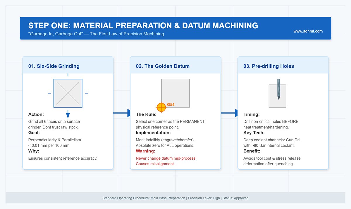
4.1 Step One: Material Preparation and Datum Machining
“Garbage In, Garbage Out.” This is the first law of precision machining. If your coordinate datum surface is misaligned, no amount of CNC compensation will fix it.
- Six-Side Grinding and Squaring: Don’t trust a supplier’s claim of “precision-milled plates.” Mount the raw block on a surface grinder and grind all six faces. Aim for perpendicularity and parallelism within <0.01 mm per 100 mm. This isn’t about appearance—it ensures consistent reference accuracy when flipping for subsequent operations.
- Establishing the Permanent Reference (The Golden Datum): Select one corner of the mold as the permanent physical reference point (G54) and mark it indelibly, for example with an engraving or chamfer. From rough machining and heat treatment to final finishing, every operation must reference this corner as the absolute zero point. Changing the datum mid-process is strictly prohibited, as accumulated errors will cause the upper and lower halves of the mold to misalign during assembly.
- Pre-drilling Process Holes (Drilling Before Hardening): All non-critical holes such as eyebolt threads or clearance slots should be completed before heat treatment. In particular, deep coolant channels (if included in the design) should be drilled using a gun drilling process with internal coolant pressure above 80 Bar to flush out chips and prevent deflection. Attempting to machine these holes after quenching is not only extremely costly in tooling but also risks releasing residual stress due to vibration, potentially causing deformation of precision cavities.
4.2 Step 2: Contour Formation (Rough Machining)
The guiding principle at this stage is “efficiency first, stress control second.” The goal is to remove excess material quickly while shaping the initial mold geometry.
- Dynamic Milling Strategy: Abandon traditional layer-by-layer cutting. Instead, adopt a high-feed, low-depth trochoidal milling strategy. This approach carries away most of the cutting heat with the chips, preventing localized annealing or thermal distortion of the workpiece.
- Scientific Stock Allowance: Determining finishing allowance is an art in itself.
- General Recommendation: Leave a single-side allowance of 0.3mm–0.5mm.
- For Deformation-Prone Materials (e.g., H13, 42CrMo): Increase allowance to 0.5mm–0.8mm. Too little, and post-heat-treatment oxidation scale or warping may prevent full cleanup; too much, and the extra grinding time and wheel wear will multiply.
- Stress Relief Grooves: For asymmetrical mold structures, pre-machine stress relief grooves on the back or non-working surfaces. This interrupts stress transmission paths during heat treatment and prevents the mold from warping like a potato chip.
4.3 Step 3: Heat Treatment and Stress Relief — The Soul of the Mold
This is the only true “black box” in mold manufacturing—and the defining factor of mold life. No matter how perfect your CNC work looks, a failed heat treatment turns that steel block into scrap metal.
- Vacuum Hardening: For bending dies, vacuum furnace heat treatment is mandatory. Compared with oil or salt quenching, vacuum processing eliminates surface oxidation and decarburization, ensuring uniform hardness and minimal deformation.
- The Indispensable Triple Tempering Process:
- First Tempering: Relieves the severe internal stress generated during quenching to prevent cracking.
- Second Tempering: Fine-tunes hardness to the target range (e.g., 42CrMo adjusted to HRC 48–52).
- Third Tempering: Often neglected by smaller shops, this step converts retained austenite, ensuring long-term dimensional stability and preventing subtle deformation over years of use.
- Cryogenic Treatment: If budget allows, insert a –196°C liquid nitrogen cryogenic cycle between tempering stages. This is not pseudoscience—physics confirms that deep cooling promotes fine carbide precipitation, enhancing wear resistance by over 200%, which is critical for molds cutting stainless or other hard sheet metals.
4.4 Step 4: Precision Grinding and Finishing
By this stage, the mold steel has hardened beyond HRC 50, making cutting extremely difficult. This is the realm of hard machining, where final precision is locked in.
- Grinding of Critical Areas: Focus on the V-groove angle, groove width, corner radius (R), and shoulder surfaces. For sectional molds, ensure mating ends are ground perfectly square so that segments join seamlessly. Maintain fitting clearances within 0.005mm–0.01mm.
- Hard Milling and Surface Finish: For complex contours unsuited to grinding, use CBN or high-hardness coated tools to mill hardened steel directly. Target surface roughness: Ra 0.4 or better.
- Removing the EDM Recast Layer: Electric discharge machining leaves behind a hard yet brittle “white layer” riddled with microcracks—a prime cause of chipping. This layer must be completely removed by hand stoning or sandblasting to ensure surface integrity.
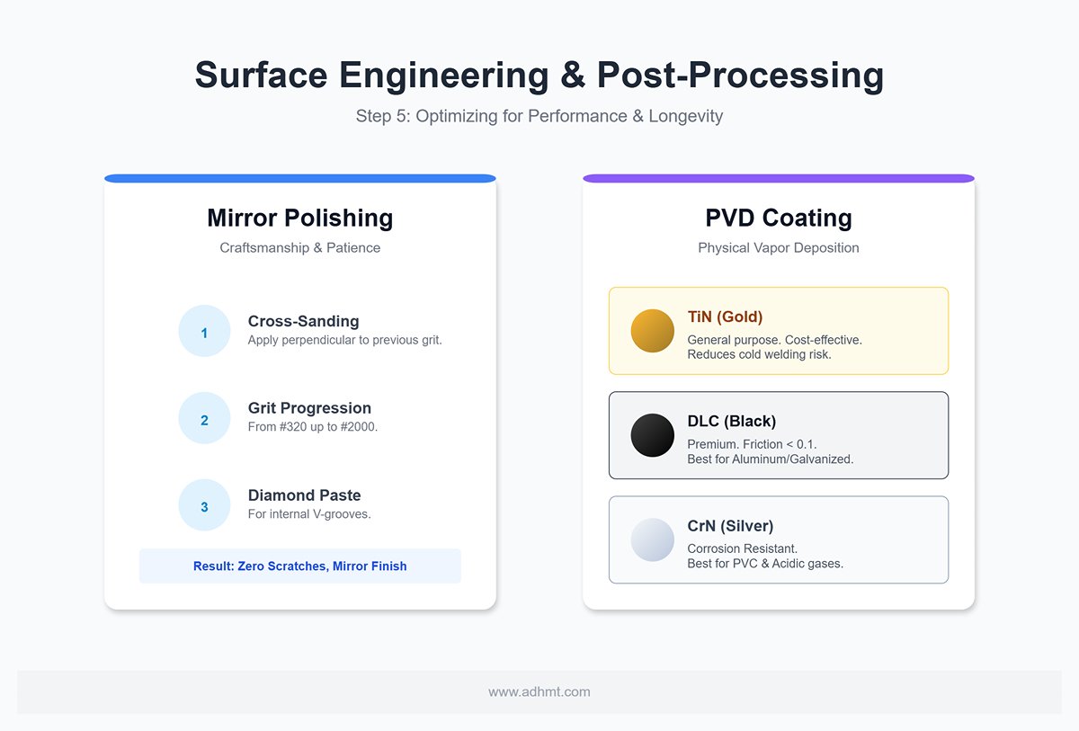
4.5 Step 5: Surface Engineering and Post-Processing
Many assume this step is merely aesthetic—it’s not. Proper surface finishing drastically reduces friction, prevents galling, and significantly extends mold life.
- Mirror Polishing: A test of patience and craftsmanship. Follow the “cross-sanding” method—each grit level (from #320 to #2000) must be applied perpendicular to the previous direction until all prior scratches disappear. For internal V-grooves, finish with diamond paste to achieve a mirror surface.
- PVD Coating (Physical Vapor Deposition): If your budget allows, PVD coating acts as a performance multiplier.
- TiN (Titanium Nitride / Gold): A cost-effective general-purpose coating that greatly reduces cold welding risk.
- DLC (Diamond-Like Carbon / Black): A premium option with an extremely low friction coefficient (< 0.1) and outstanding dry lubrication. Ideal for aluminum or galvanized sheet forming, it completely eliminates material buildup during bending.
- CrN (Chromium Nitride / Silver): Best for molds processing PVC or other materials that emit acidic gases—CrN provides superior corrosion resistance.
V. Verification, Debugging, and Quality Control
When a die is removed from the grinder or milling machine, the manufacturing process is only halfway complete. Many catastrophic failures of self-made dies don’t occur in the machining center—they happen at the very first press test.
A die that hasn’t undergone rigorous verification may not only produce scrap parts but also become a potential time bomb under dozens of tons of hydraulic pressure. This chapter establishes a set of acceptance standards ranging from “cold-state inspection” to “hot-state press testing.”
5.1 Static Inspection Criteria
Before mounting the die on the press brake, a thorough “cold-state inspection” must be carried out on the bench. Any micron-level deviation overlooked during static measurement can be amplified into angular errors on the press brake—or even result in die fracture.
- Height Consistency Check:
- Core Principle: For segmented or long dies, the most critical dimension isn’t the total height but the consistency of that height along the entire length.
- Procedure: Invert the die on a precision surface plate (with the V-groove facing downward) and run a dial indicator along the tang surface.
- Tolerance: The height variation along the full length should be within 0.02 mm. If one section is higher by 0.05 mm, it will bear most of the load first during bending, easily causing edge chipping or indentation on the workpiece.
- Non-Destructive Testing (NDT – Dye Penetrant Inspection):
- Rationale: Heat treatment—especially manual flame hardening—can easily cause microcracks at the V-groove root or other stress concentration areas that are invisible to the naked eye.
- Procedure: Apply a dye penetrant (PT) as follows: clean → spray red penetrant and wait 10 minutes → clean again → apply white developer.
- Acceptance Criteria: If any red lines or spots appear on the white background, the die must be immediately scrapped. Under high hydraulic pressure, such microcracks can rapidly propagate and cause the die to shatter and eject violently.
- V-Groove Symmetry:
- Importance: The V-groove centerline must align precisely with the centerline of the mounting tang.
- Testing Method: Use a universal protractor or optical projector. If the center offset exceeds 0.05 mm, the bent parts will show uneven leg lengths and asymmetric bend angles—issues that are difficult to correct even with CNC backgauge compensation.
- Hardness Validation:
- Common Pitfall: Never test only one point.
- Procedure: Use a portable Leeb hardness tester to measure the shoulder areas of the V-groove at both ends and in the middle.
- Tolerance: Hardness variation should be within ±2 HRC. A sudden drop in hardness at any section indicates over-tempering (a soft spot), which will quickly wear and indent during use.
5.2 Dynamic Test Procedure (SOP)
Never perform a full-tonnage bend directly. Follow the step-by-step test procedure below—this protects both the die and the operator’s safety.
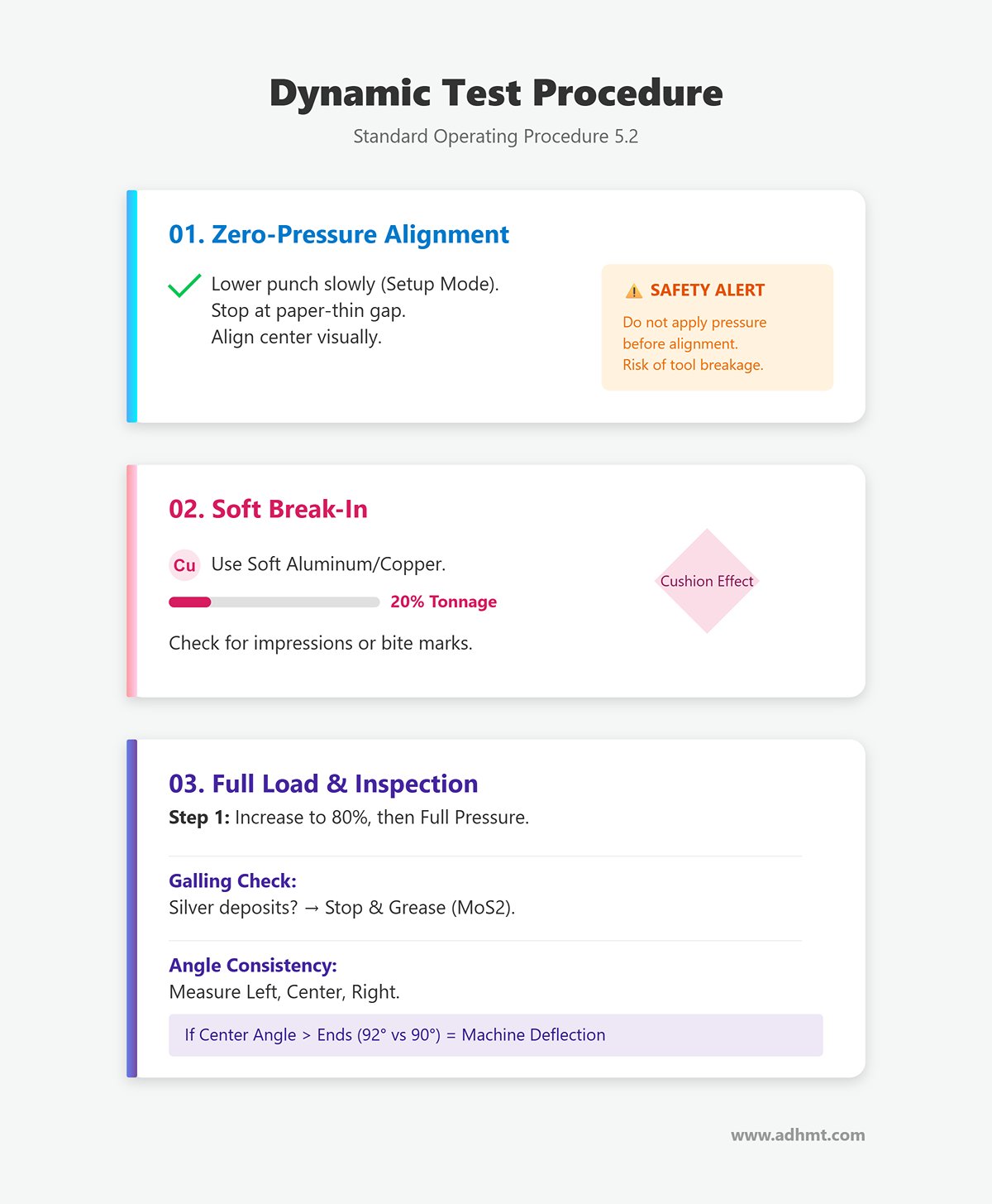
- Stage 1: Zero-Pressure Alignment
- Procedure: After installing the upper and lower dies, switch the press brake to “setup” or “slow down” mode. Lower the punch tip slowly into the V-groove, stopping just before contact (leaving a paper-thin gap).
- Visual Check: Ensure the punch tip aligns exactly with the center of the V-groove. For self-made dies, slight adjustment of the lower die seat screws may be needed to correct machining offset.
- Warning: Never apply pressure before alignment. Any side load can instantly snap the punch tip.
- Stage 2: Soft Break-In
- Materials: Prepare several strips of soft aluminum or copper equal in thickness to the design material.
- Purpose: Soft metals act as a cushion, preventing brittle contact damage if slight burrs or geometric errors exist in the die.
- Execution: Apply approximately 20% of the theoretical tonnage and perform a trial bend on the soft plates. Check for impressions or bite marks inside the V-groove.
- Stage 3: Full Load and First Article Inspection
- Procedure: Replace with the actual production material, set the tonnage to 80% of the calculated value, and gradually increase to full pressure.
- Galling Check: After the first bend, remove the part and inspect both the outer bend area and the V-groove shoulders under magnification.
- Observation: If silver-white metal deposits appear on the die shoulder, it indicates poor surface finish or insufficient lubrication.
- Countermeasure: Stop immediately, remove the buildup with a fine stone, and apply molybdenum disulfide lithium grease. Otherwise, severe galling will occur within a few dozen bends.
- Angle Consistency Verification: Measure bend angles at the left, center, and right positions of the part.
- If the center angle is larger than the ends (e.g., ends at 90°, center at 92°), it indicates elastic deformation of the die or machine deflection. Activate the press brake’s crowning compensation function. If unavailable, the die’s rigidity design has failed and it should be downgraded for lighter use.
🏁 Final Release Criteria: A self-made die qualifies for production only after passing the PT inspection and successfully bending 50 consecutive parts with no visible scratches on the V-groove surface and stable bend angle deviation within $\pm 0.5^\circ$. Remember: your signature as the maker is a personal guarantee of the die’s safety throughout its entire service life.
VI. Common Failures and Prevention Guide
Even the most experienced die makers cannot ensure flawless performance every time. Press brake dies operate under extreme stress and friction. This chapter exposes the hidden “time bombs” within the metal and provides field-tested repair and optimization techniques to help you evolve from a mere fabricator into a true problem-solving expert.
6.1 Typical Manufacturing Defects and Remedies (The “Hidden Factory” Issues)
Some defects are introduced during manufacturing but don’t reveal themselves until mass production—often with catastrophic results. Identifying and correcting these latent flaws is the final line of defense before delivery.
- Heat Treatment Deformation – The “Banana Bend” Effect
- Phenomenon: After quenching, long strip-shaped molds (especially segments over 500 mm) often exhibit noticeable bowing or twisting, preventing proper contact with the press brake bed during installation.
- Root Cause: Asymmetric release of residual internal stress and uneven volumetric expansion during the martensitic phase transformation.
- Correction and Prevention:
- Prevention Strategy: Apply the “Triple Stress-Relief Method.” Perform stress-relief annealing after rough and semi-finish machining. During quenching, the mold must be hung vertically in the furnace—horizontal positioning is strictly prohibited.
- Remedial Action (Localized Heat Straightening): For minor bends (< 1 mm/m), use an oxy-acetylene flame to quickly heat the back side of the convex area (non-working surface). The resulting thermal expansion and contraction generate counter-stress to straighten the mold. This requires high skill, and the part must undergo low-temperature tempering afterward to relieve newly introduced stresses.
- EDM Altered Layer (EDM White Layer) — A Breeding Ground for Microcracks
- Phenomenon: To achieve sharp accuracy at the bottom of the V-groove, many manufacturers use wire EDM. However, tiny cracks often appear at the groove bottom early in service life.
- Root Cause: The high temperature generated during EDM produces a remelted surface layer about 5–20 μm thick (the white layer). Although extremely hard (HRC 65+) this layer is brittle and filled with microscopic cracks.
- Prevention: Always perform “white layer removal.”
- Mechanical Method: Manually polish the bottom of the V-groove using an oilstone or diamond paste until the gray-white spark texture disappears and the metallic luster of the substrate is exposed.
- Chemical Method: For complex geometries, use acid pickling to remove the remelted layer. Skipping this step allows fatigue cracks to initiate from the white layer and rapidly propagate into the core, leading to mold failure.
- Machining Error Repair (Welding Restoration) — Pitfalls and Best Practices
- Scenario: Overcutting during CNC finish milling or edge chipping during service.
- Challenge: Tool steels (such as 42CrMo or H13) have poor weldability. Direct welding often causes cracking around the weld zone due to heat-affected zone embrittlement.
- Expert Solutions:
- Preheating Is Essential: The entire mold must be preheated to 250°C–300°C before welding.
- Material Matching: Never use standard stainless-steel filler wire. Use tool steel filler with matching chemical composition (e.g., for 4140 or H13) to ensure consistent hardness after repair.
- Laser Cladding: When available, laser welding is preferred. Its minimal heat input (HAZ < 0.2 mm) preserves the base material properties and leaves virtually no repair marks.
6.2 Troubleshooting During Use (Pain Point Solutions)
Once you put your custom-made mold into production, the real test begins. The following outlines logical solutions to the most common on-site issues.
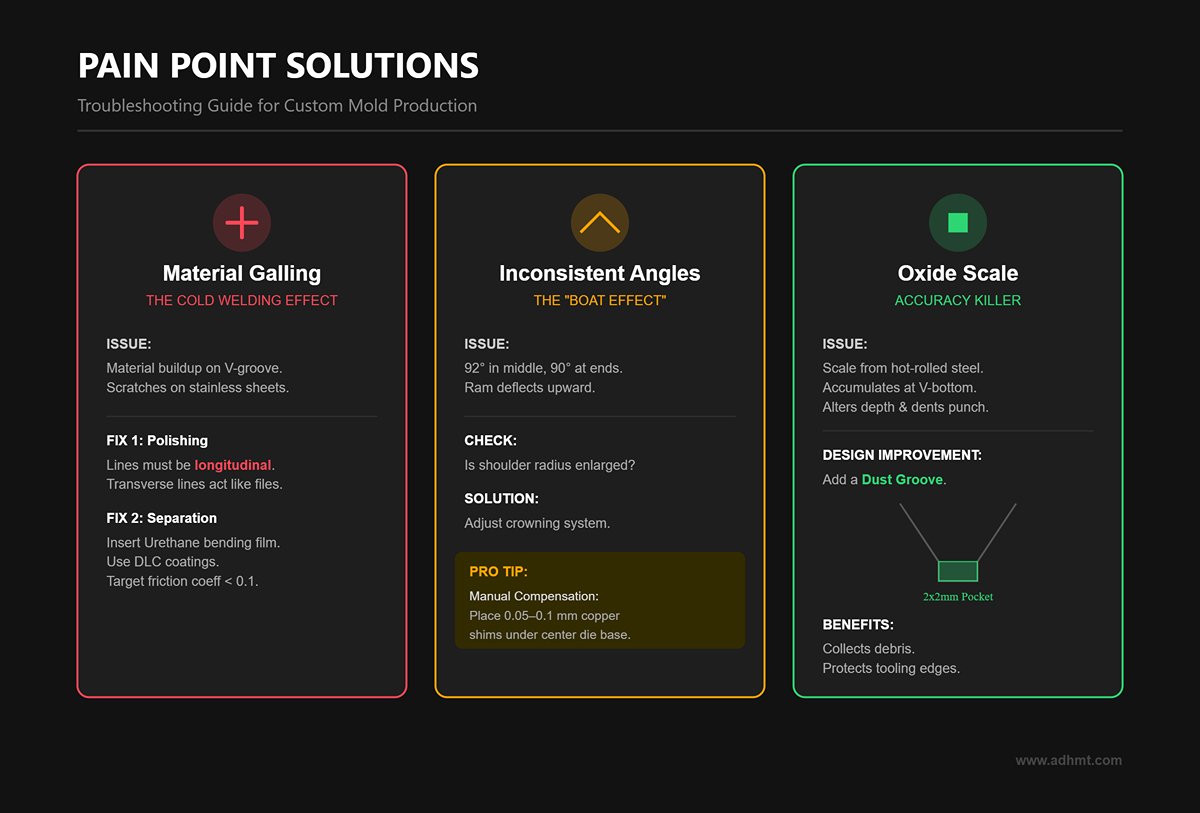
- Material Galling — The Destructive Cold Welding Effect
- Phenomenon: When bending stainless steel or galvanized sheets, material buildup appears on the shoulders of the V-groove, causing deep scratches or dents on the workpiece surface.
- Root Cause: Under high pressure, microscopic cold welding occurs between the workpiece and mold surfaces.
- Solutions:
- Optimize Polishing Direction: Check your polishing pattern. The final polishing lines on the V-groove shoulders must run longitudinally (along the mold length). Transverse polishing lines act like files that hinder material flow.
- Physical Separation: In severe galling cases, insert a urethane bending film between the workpiece and the lower die, or upgrade the mold surface with advanced coatings (e.g., DLC diamond-like coatings) to reduce the friction coefficient to below 0.1.
- Inconsistent Angles — It’s Not Always the Mold’s Fault
- Phenomenon: Within the same batch of sheet material, bend angles vary; or the mold produces 92° in the middle and 90° at both ends (the “boat effect”).
- Diagnostic Logic:
- Check Mold Wear: Measure whether the V-groove shoulder radius has enlarged. Worn shoulders let the sheet sink deeper, yielding smaller angles.
- Machine Deflection: If the center angle is larger and the ends smaller, the press brake ram likely deflects upward under load. This isn’t a mold issue—it requires adjusting the machine’s crowning compensation system.
- Pro Tip: If the machine lacks automatic crowning, compensate manually by inserting 0.05–0.1 mm copper shims under the center of the lower die base to create a counteracting bulge.
- Oxide Scale Build-up — The Hidden Accuracy Killer
- Phenomenon: When bending hot-rolled or mill scale steel sheets, angle deviations gradually appear, and the bottom of the V-groove becomes dirty and dented.
- Root Cause: Detached iron oxide particles accumulate at the sharp bottom of the V-groove, altering its actual depth. These hard particles can also dent the punch tip.
- Design Improvement:
- When designing a custom mold, always include a dust groove at the bottom of the V-slot. Mill a 2 mm × 2 mm square or round pocket at the groove base to collect debris and scale, preventing them from affecting forming forces. This significantly reduces cleaning frequency and protects the tooling edges.
VII. Conclusion
Creating a high-performance press brake die is an engineering feat balancing material science, design, and metallurgy. From choosing between "DIY" and "Buy" to mastering the critical heat treatment process, every step defines your tool's longevity and accuracy. By following this guide, you are building a production asset that ensures long-term efficiency. Success ultimately lies in the details: the right steel, precise engineering, and rigorous testing.
For guaranteed precision without the trial and error, partner with ADH Machine Tool. We deliver industry-leading press brake tooling designed for durability and performance. To learn more about customized tooling solutions or request a quote, feel free to contact us.


