How to make a small press brake isn't just about bolting steel together—it's about engineering precision into a compact footprint. Whether you're fabricating a DIY solution for your workshop or evaluating small-format industrial equipment, success demands more than basic metalworking skills.
This guide deconstructs the entire lifecycle: from calculating your true ROI and mastering the force equations behind deflection-free bends, to sourcing the right materials and integrating fail-safe hydraulics. Stop treating sheet metal bending as guesswork. Learn how master-level craftsmanship, strategic material selection, and future-proof automation can transform a small press brake from a "good enough" tool into a high-margin production asset.
I. Strategic Decision-Making and Feasibility Evaluation Framework
Before you pick up a welder or order steel, it’s essential to conduct a rigorous and honest “dry run.” Building a small press brake isn’t as simple as welding together a few pieces of metal—it’s a complex system project that touches on mechanical engineering, fluid dynamics, and precision fabrication.
This chapter provides a structured decision-making framework to ensure that your investment of time and money results in a functional machine tool rather than an expensive pile of scrap metal.
1.1 Comprehensive ROI (Return on Investment) Analysis
Many DIY enthusiasts fall into the trap of assuming that building something yourself is always cheaper than buying. In reality, the total cost is a combination of tangible material costs and intangible engineering costs.
- Tangible Cost Comparison (Hard Costs):
- Entry-Level Commercial Machine: A standard 20-ton manual or hydraulic press brake (for example, kits from brands like SWAG Offroad) typically sells for between $300 and $800 (jack not included), while fully assembled hydraulic models often start at $3,000 or more.
- DIY Build Cost: If you already have scrap steel on hand, material expenses can be as low as $150. However, if you need to purchase all new steel, high-strength bolts, hydraulic jacks, and spring assemblies, your total bill of materials (BOM) will usually fall between $300 and $500.
- Conclusion: On paper, DIY construction can save 50–80% compared to buying new—but only if you don’t assign a labor cost to your own time.
- Intangible Value:
- Customization Premium: The greatest advantage of a self-built press brake is the ability to tailor it precisely to your needs. You can design it to fit a specific corner of your workshop or to accommodate particular parts—such as deep throats or unusually wide U-channels—that off-the-shelf models cannot handle.
- Skill Capital: Completing the project means gaining valuable experience in heavy-plate welding, stress relief, and hydraulic integration—skills that serve as long-term technical investments.
1.2 Difficulty Levels and Build Pathways (Customized Roadmap)
To avoid overestimating your abilities, it’s important to match your available tools and skill level with an appropriate build plan.
| Difficulty Level | Level 1: Conversion Build | Level 2: Fabricator’s Standard | Level 3: Engineer’s Choice |
|---|---|---|---|
| Core Design | Modify an existing H-frame shop press with a press brake die kit. | Fully independent frame with inverted cylinder or bottom-lift configuration and guided slide system. | Includes CNC backgauge, precision linear rails, and synchronized or deflection-compensated hydraulics. |
| Best Use Case | Occasional bending of short brackets or tabs under 6 mm thick. | Regular production of structural parts under 600 mm in length and 10 mm thick. | High-precision fabrication requiring ±0.5° bend accuracy for large sheet-metal housings or precision parts. |
| Required Tools | Angle grinder, drill press, basic stick/MIG welder. | Metal bandsaw or cold saw, high-power MIG welder, magnetic drill. | Lathe/mill (for guide post machining), TIG welder, precision measuring instruments. |
| Estimated Labor | 1–2 weekends (10–20 hours). | 3–5 weekends (40–60 hours). | 3+ months (150+ hours). |
Strategic Recommendation: For roughly 90% of personal workshops and small startups, Level 2 strikes the ideal balance. It delivers professional functionality without the high machining costs associated with industrial-grade designs, while avoiding the precision limitations of simple conversion builds.
1.3 Capability Self-Assessment and Resource Audit
Engineering failures often stem from misjudging one’s own capabilities. Before starting, honestly evaluate yourself across these three dimensions:
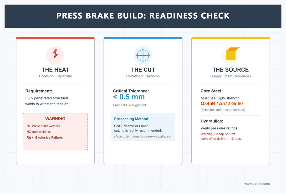
Hot-Work Capability (The Heat):
- The press brake frame must withstand enormous tensile forces. Can you perform fully penetrated structural welds?
- Warning: If your welder is a basic 110 V model or your technique is limited to tack welding, do not attempt load-bearing welds. A failed joint under pressure is not just a mechanical failure—it’s a potential explosive hazard.
Cold-Work Precision (The Cut):
- Bending accuracy depends on the parallel alignment between the punch and die. Can you cut steel plates with a tolerance better than 0.5 mm?
- Without access to CNC plasma or laser cutting, achieving this precision by hand will demand significant time and patience.
Supply Chain Resources (The Source):
- Core Steel: Can you source high-strength steel such as Q345B (or ASTM A572 Gr.50) locally? Ordinary mild steel tends to deform plastically under long-term high loads.
- Hydraulic Components: Do you have access to cylinders with verified pressure ratings? Cheap “20-ton” jacks often deliver less than 12 tons in reality, invalidating your design calculations.
Decision Point: If you answered “no” to two or more of the above, start with a Level 1 conversion kit or outsource critical machining tasks. Focus your effort on assembly and calibration instead. That’s not compromise—it’s engineering wisdom.
II. Core Engineering Principles and Design Parameters (The Engineering Core)
Before cutting your first piece of steel, you must first master the laws of physics. Designing a press brake is not a geometric puzzle—it’s a calculated balance between force, stress, and stiffness. This chapter provides the engineering logic necessary to build a machine that can both bend metal effectively and survive the process intact.
2.1 Fundamental Force Calculations (No Guesswork Allowed)
The most common and dangerous mistake in DIY press-brake projects is guessing the required tonnage. Too little pressure leads to jams and incomplete bends; too much pressure combined with weak structure can tear the frame apart or cause catastrophic failure. Always trust the math—not luck.
Air Bending Tonnage Formula — For most DIY projects, we’ll use the air bending method, where the sheet is not pressed fully into the bottom of the die but is instead formed while suspended. For mild steel with a tensile strength of roughly 420–450 MPa, the required tonnage F (tons per meter) can be estimated using the following empirical formula:
- S (plate thickness, mm): The maximum material thickness you plan to bend.
- V (die opening width, mm): This is the critical variable.
- F (required pressure per meter, tons): Be careful—the unit is tons per meter of bend length.
Essential Engineering Rules:
- Golden Ratio — V = 8S: To achieve optimal bending results and balanced force distribution, the die opening width V is typically set to eight times the plate thickness. For example, when bending a 6 mm steel plate, choose a 48–50 mm die opening.
- Leverage Effect: The formula shows that force increases with the square of the plate thickness but decreases as the die opening widens. If you want to bend thicker plates with less force, increase the die width—though this will produce a larger bend radius and less sharp corners.
- Safety Factor: After calculating the theoretical tonnage, always multiply it by a safety factor of 1.3 to 1.5. This accounts for variations in material hardness and compensates for possible efficiency losses in DIY hydraulic systems.
Example: Suppose you plan to bend a 500 mm-wide, 6 mm-thick Q235 steel plate using a 50 mm die opening.
The theoretical tonnage is F_theoretical = (65 × 6²) / 50 = 46.8 tons/m.
Actual required force = 46.8 × 0.5 m = 23.4 tons.
Conclusion: A 20-ton jack won’t be sufficient—you’ll need to design a power system rated at least 30 tons.
2.2 Structural Mechanics and Deflection Control
Many DIY press brakes can generate enough pressure, yet the bent parts turn out uneven—typically with a wider angle in the center than at the ends (e.g., 95° in the middle, 90° at both edges). This distortion is caused by deflection.
Stiffness Over Strength — In mechanical design, strength keeps the machine from breaking, while stiffness ensures accuracy. Even a heavy I-beam will flex like a bow under a 20-ton center load.
- Resisting the “Canoe Effect”: When the ram presses downward, the upper beam tends to arch upward, while the lower beam bends downward, reducing pressure at the center of the workpiece.
- Solution: Don’t rely on solid flat plates for load-bearing beams—they’re expensive and inefficient. Instead, leverage the moment of inertia principle. A 200 mm-high I-beam or rectangular tube has far greater bending resistance than a 50 mm-thick solid plate, despite being lighter. Design mantra: increase beam height, not just wall thickness.
- Stress Concentration and Corner Design: If you’re using a flat-plate tab-and-slot structure similar to SWAG Offroad’s design, remember: no internal corner should be perfectly sharp. In your laser-cut drawings, every load-bearing corner must include R3–R5 relief holes. Sharp internal corners are stress concentrators, and under repeated high-pressure cycles, cracks will start there.
- Guide System Parallelism: The ram must move strictly vertical, with no side play. Simple tube-in-tube DIY guides often introduce clearance issues.
- Advanced Solution: Use graphite bronze bushings paired with precision shafts, or clamp the main columns using skate bearings. This ensures the ram remains aligned even during off-center bending, preventing jamming or tilt.
2.3 Power System Selection Logic
The power source is the heart of your press brake—it defines how the machine feels in operation and its overall productivity.
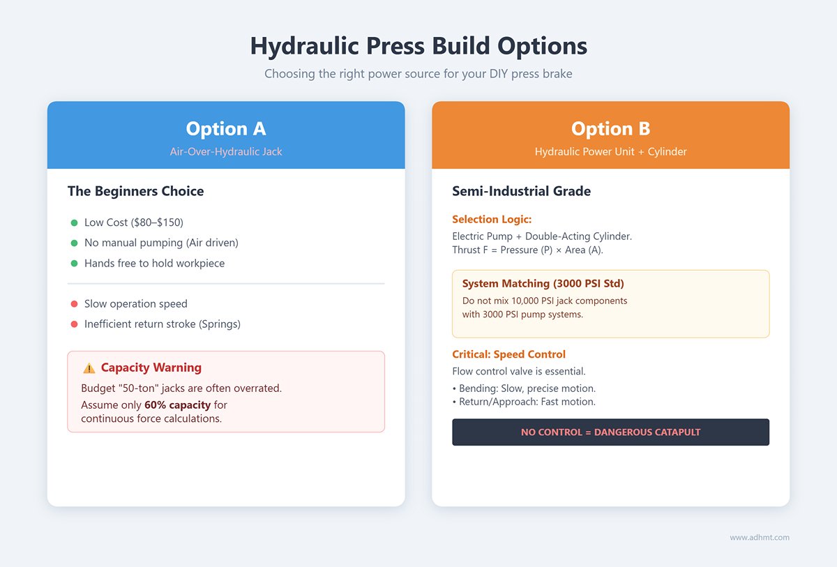
Option A: Air-Over-Hydraulic Jack — The Beginner’s Choice
This is the most cost-effective setup, using an air compressor to drive a hydraulic jack.
- Advantages: Low cost ($80–$150), no manual pumping, and both hands free to hold the workpiece.
- Limitations: Slow operation; return stroke typically relies on springs, making it inefficient for frequent production.
- Warning: Many budget jacks labeled “50 tons” are grossly overrated. Assume only about 60% of the stated capacity for continuous force calculations.
Option B: Standalone Hydraulic Power Unit + Double-Acting Cylinder — Semi-Industrial Grade
If efficiency is your goal, this is the logical next step.
- Selection Logic: Pair an electric hydraulic pump station with a double-acting cylinder. The hydraulic thrust F is calculated as F = P × A (pressure × piston area).
- System Matching: The industrial standard is 3000 PSI (≈ 21 MPa). Never mix components designed for 10,000 PSI jacks with 3000 PSI pump systems, and don’t attempt to drive high-pressure jacks using cheap gear pumps.
- Speed Control: A flow control valve is essential. The bending stroke requires slow, precise motion, while approach and return strokes should be fast. A press brake without speed control is a dangerous catapult.
Design Safety Rule: Regardless of the power system chosen, always include a pressure gauge. Applying pressure blindly can damage tooling and lead to severe accidents. You must know exactly when your system is approaching its limits.
III. Supply Chain Management: Material Selection and BOM Strategy
Between your design blueprints and the finished machine lies a minefield: the supply chain. Most DIY projects fail not because of poor design, but due to a “good enough” mindset during material procurement.
Remember—steel’s microstructure determines whether your press brake becomes a precision tool or scrap metal. This chapter will teach you to evaluate your BOM (Bill of Materials) like a professional sourcing manager.
3.1 Structural Steel Selection Guide
Stop writing just “mild steel” in your BOM. For a machine that must endure tens of tons of pressure, every downgrade in steel grade shortens its service life exponentially.
- S235JR (A36) vs. S355MC (A572 Gr.50): A Leap in Strength Class
- Beginner’s Pitfall: S235JR (ASTM A36) is the most common “commodity grade” steel on the market. While it welds reasonably well, its carbon and impurity levels vary widely. Under high stress, its relatively low yield strength (around 235 MPa) forces you to use thicker, heavier plates to maintain rigidity.
- Expert Recommendation: For the main frame (side plates) and load-bearing beams of a press brake, it’s strongly advised to upgrade to S355MC or ASTM A572 Grade 50. These are low-alloy, high-strength steels with roughly 50% greater yield strength (up to 355 MPa). In practice, that means your machine frame resists permanent deformation even at equal weight.
- Insider Insight: If you plan to outsource laser cutting, S355MC is the superior choice. Its finer grain structure and tighter silicon control result in smoother fiber‑laser cut surfaces, drastically reducing the tedious post‑grinding and deburring time.
- The Necessary “Flatness Premium”: Eliminating Residual Stress
- Say Goodbye to Mill Scale: The hard, brittle oxide layer on standard hot‑rolled plates can damage laser optics and contaminate weld pools. Specify HRPO (pickled and oiled) sheet in your BOM. The slight cost increase per ton saves countless grinding discs and labor hours.
- Fighting the Memory of Stress: Steel coils carry internal “memory.” When cut, they release stress and parts can warp like potato chips—known as oil canning. For critical components such as sliders and guide‑rail mounts, this distortion can be fatal to precision.
- Gold Standard: If your budget allows, source plates processed by Stretcher Leveling. This method completely erases residual stress memory, ensuring long, narrow parts stay straight after cutting and saving you costly precision milling.

3.2 Tooling Material Science
Press‑brake tooling is the machine’s “teeth”—the only components that directly contact the workpiece and endure extreme pressure. Treat your tooling as a core asset, not a consumable.
- Material Showdown: 42CrMo4 vs. C45
- Limitations of C45 (1045 Steel): Many DIY builders favor cold‑rolled 1045 steel for tooling because it’s inexpensive and easy to machine. But it’s suitable only for aluminum or occasional thin sheet steel. Under sustained high pressure, the V‑groove quickly wears and deforms, ruining bend accuracy.
- Industry Standard: 42CrMo4 (4140 Steel): This is the only correct choice for precision sheet‑metal tooling. Select pre‑hardened 4140 for outstanding toughness and strength. With laser surface hardening, it can reach HRC 55–60—able to bend stainless steel under tens of tons of force without chipping or collapsing.
- Coating Secrets: The Anti‑Stick Charm for Aluminum
- When frequently bending soft aluminum (e.g., 5052 series), you’ll encounter the dreaded galling phenomenon—aluminum particles weld themselves to the steel die under pressure, scratching every subsequent part.
- Solution: Beyond polishing, consider applying TiCN (Titanium Carbonitride) or DLC (Diamond‑Like Carbon) coatings to the upper die. This micron‑thin armor lets aluminum glide through the V‑groove as if on ice, eliminating surface marks. For DIY builders without access to coatings, a urethane film placed on the lower die is a highly cost‑effective alternative.
3.3 Procurement Strategy and Pitfall Avoidance
The steel and hardware market is full of hidden traps and misinformation. The following strategies will help you protect both your budget and your safety.
- Thickness Trap: Nominal vs. Minimum Thickness
- Under ASTM A568, mills are permitted to supply plates below nominal thickness. When you order “2.0 mm” sheet, unscrupulous suppliers might deliver material measuring only 1.85 mm, still within theoretical weight tolerance.
- Engineering Consequences: In precision bending assemblies, that 0.15 mm cumulative deviation can cause excessive clearance in slider guides or invalid strength calculations.
- Countermeasure: Your purchase order or notes must specify “Minimum Thickness” (actual delivered thickness). If collecting material in person, bring a micrometer and inspect on site—never pay for air.
- Fastener Grade Red Line
- Never use ordinary hardware‑store bolts (typically Grade 2 or 4.8) in the main load‑bearing structure of a press brake.
- Mandatory Standard: All tensile or shear joints must use Grade 12.9 (metric) or Grade 8 (imperial) high‑strength alloy‑steel bolts, usually with a black oxide finish. A single inferior bolt fracture can turn into a bullet when hydraulic pressure is released.
- The Truth About MTRs (Material Test Reports)
- When purchasing critical shaft materials such as guide posts or pins, never rely on verbal assurances. From legitimate steel suppliers, requesting an MTR (Mill Test Report) is your right. While handheld XRF analyzers are impractical for individuals, learning to read the MTR’s chemical composition—carbon, manganese, chromium content—helps confirm you’re buying genuine 4140, not overpriced A36 disguised as alloy steel.
IV. Master-Level Manufacturing Process: From Steel to Machine
Building a press brake capable of maintaining long-term precision is far more than a contest of welding skills—it’s an engineering campaign centered on stress management and precision referencing. At this stage, we transform the lines of a blueprint into cold, tangible reality. Any compromise in process discipline will eventually punish you in the form of angular deviations in your workpieces.
4.1 Stage One: High-Precision Frame Fabrication (The Skeleton)
Most DIY enthusiasts assume that frame fabrication is just about “cutting, aligning, and welding.” In the professional world, however, welding marks only the beginning of the process. The real secret lies in the post-weld ritual known as stress relief.
- The Invisible Enemy: Residual Welding Stress When high-intensity arcs melt steel plates, the extreme thermal expansion and contraction lock immense tensile forces inside the structure. If you proceed to machining immediately after welding, months later—when these stresses begin to release naturally—your frame will warp like a twisted branch, destroying the parallelism of the guideways.
- Industrial-Grade Solutions: Heat Treatment vs. Vibratory Stress Relief
- Thermal Annealing (The Gold Standard): This is the most thorough approach. The multi-ton frame is placed inside a massive annealing furnace, heated to around 600°C, held at temperature, and then cooled slowly with the furnace. This process eliminates over 90% of internal stress and refines the metal’s microstructure. Though costly and often outsourced, it’s the only path to crafting a truly “heirloom-grade” machine.
- Vibratory Stress Relief (VSR): A cost-effective alternative. Vibrators are mounted at specific points on the frame and run for several hours to induce resonant vibration, dissipating 30–50% of surface-level peak stress. For small workshops with limited budgets, this is a practical compromise.
- The Iron Rule of Single Setup: Floor Boring After stress relief, the frame enters the machining phase. Remember one absolute rule: a unified reference system. All critical holes (cylinder mounts, guide surfaces, and worktable planes) must be machined in a single setup on a large floor-type boring and milling machine. Never reposition the frame for multiple passes—manual alignment will never achieve the 0.02 mm/m parallelism that only heavy industrial mother machines can deliver.
4.2 Stage Two: The Ram and Guiding Mechanisms

The ram is the heart of a press brake. It must endure hundreds of tons of lateral tearing force while maintaining micron-level vertical precision.
- Abandon the Torsion Bar, Embrace Dual Closed-Loop (Y1/Y2 Axis) Traditional torsion-bar synchronization is bulky and difficult to calibrate. Modern master-level designs adopt independent electro-hydraulic synchronization on Y1 and Y2 axes, meaning each cylinder is decoupled and controlled independently by the CNC system.
- The Truth About Linear Encoders Real precision comes from closed-loop feedback. Never rely on piston travel calculations—under high pressure, the frame elastically stretches. Instead, install micron-accurate linear encoders on both sides of the ram (brands such as Heidenhain or Givi are industry benchmarks).
- Critical Design Detail: Mount the encoders on the C-frame to measure the actual distance between the ram and the worktable, not the cylinder position. This ensures that even if the frame deforms under load, the encoders can direct the hydraulic system to compensate in real time, keeping the bending angle consistent.
4.3 Stage Three: Tooling System and Quick-Change Mechanism
In an era of high-mix, low-volume production, setup time equals profit. If you’re still tightening bolts one by one with a hex wrench, you’ve already lost the race.
- Hydraulic Clamping and Self-Seating Alignment Integrating an industrial-grade hydraulic clamping system (modeled after WILA New Standard or Promecam quick-change interfaces) marks a qualitative leap forward.
- Operational Revolution: With a single button press, hydraulic pins retract, and the tooling pops into place with self-seating precision. The entire setup process drops from 30 minutes to just 2. For a busy job shop, that time savings alone can pay for another machine each year.
- Top-Level Error Prevention Design For those pursuing perfection, embed RFID reading points within the tool holders. If an operator mistakenly attempts to bend 6 mm plate using a V10 die, the CNC system detects the mismatch and locks the machine. This poka-yoke (error-proofing) design prevents costly tooling damage and protects your investment.
4.4 Stage Four: Backgauge and Positioning System
The backgauge is far more than a simple stop block—it’s the final line of defense for accuracy and the key to handling complex geometries.
- From 2 Axes to 6 Axes
- The Necessity of the R Axis (Vertical Lift): Many DIY designs overlook this feature. When bending parts with Z-shapes or reverse flanges, the stop fingers must lift automatically to avoid interference. The presence of an R axis often separates amateur builds from professional-grade machines.
- Z1/Z2 Axes (Left and Right Movement): For workshops frequently changing workpiece widths, automated Z-axis adjustment between stop fingers saves labor and eliminates the need for operators to manually adjust from the back of the machine.
- Material Science of Stop Fingers The stop fingers directly contact the sheet edge and must be both wear-resistant and electrically insulated.
- Material Standards: The contact surfaces must be made from hardened steel or carbide. Otherwise, within three months, sharp sheet edges will gouge the surface, degrading positioning accuracy from 0.05 mm to 0.5 mm.
- Electrical Isolation: If your system supports touch-sensing feedback, the stop fingers must be electrically insulated from the frame to ensure the sensing current remains stable and interference-free.
V. System Integration, Safety Certification, and Commissioning
Fabricating the physical structure of a press brake is only half the journey—the soul lies in giving it a nervous system and muscle memory. At this stage, cold steel, intricate hydraulic lines, and precise electronics must merge into one coherent entity.
Remember, this isn’t just about powering it on—it’s the defining moment that determines whether your machine becomes a high-performance production tool or a ticking time bomb in your workshop.
5.1 Hydraulic and Electrical System Integration
A press brake is essentially a precision marriage between electrical control and hydraulics. The biggest misconception among DIY builders is believing components are “plug-and-play.” In reality, every valve block and every relay must be reintegrated and finely tuned to your specific environment.
Hydraulic Valve Response Race: Eliminate Lag The core of any hydraulic system lies in its control accuracy and response speed. When selecting your main control valve assembly, you are faced with two distinct technological paths:
- Valve-controlled system (represented by Rexroth): This is the traditional industrial standard. It relies on proportional valves to throttle hydraulic oil flow. While the technology is highly mature, its millisecond-level response can be sluggish when micron-level positioning is required. Moreover, because speed regulation is achieved through throttling, energy losses are converted into heat, raising oil temperature. For low-cost retrofits, however, it remains the safest choice.
- Pump-controlled servo system (benchmarked by Hoerbiger ePrAX): This represents the cutting edge—the “crown jewel” of modern precision press brakes. Here, a servo motor is directly coupled to the hydraulic pump, allowing flow and pressure to be controlled by adjusting motor speed and direction, eliminating the need for numerous throttling valves.
- Real-world advantages: During the fast descent, the ram moves primarily under gravity, consuming almost no electricity; during pressure holding, the motor runs at low speed. As a result, oil temperature typically stays more than 20°C lower than in valve-controlled systems, and seal life can double. If your goal is industrial-grade energy efficiency and near-silent operation, a servo pump control setup is strongly recommended.
Managing the risk of electrical cabinet “thermal death” Ninety percent of DIY CNC system crashes are not caused by software bugs but by overheating or short circuits inside the electrical cabinet. Workshop air is often saturated with oil mist and conductive metal dust.
- Fatal mistake: Using a standard exhaust fan. Such fans draw in air laden with iron particles, which then settle on circuit boards and inverters. Once moisture is introduced, a short circuit can literally blow up the system.
- Master-level protection: Maintain positive pressure and internal cleanliness inside the electrical cabinet at all times.
- Option A: Install an industrial-grade cabinet air conditioner to ensure constant temperature and humidity.
- Option B (cost-effective): Use a Vortex Cooler. Simply connect compressed air, and it will generate cold airflow while keeping the cabinet’s internal pressure slightly above ambient, physically blocking dust intrusion.
5.2 Mandatory Safety Protocols

In press brake manufacturing, safety is not a suggestion—it’s a survival rule. A press brake is essentially a giant guillotine. Under European and American standards, operating one without certified safety devices is illegal. In China, this remains one of the most common causes of finger injuries.
Generational leap in laser safety systems Abandon outdated light curtains. They merely detect human entry into danger zones and cannot distinguish between a finger and a workpiece. Since press brake operations often require manual support of the sheet, light curtains cause constant emergency stops, making normal operation impossible. What you need is a dynamic laser protection system:
- Lazersafe (IRIS) – Industry gold standard: Developed in Australia. Its key innovation is Block Laser technology, where the laser beam moves parallel just beneath the punch tip.
- Bend Speed Management: The system monitors ram speed, allowing rapid descent until the punch tip is only 2 mm from the sheet, then shifting to slow approach. If it detects a finger obstruction, the machine executes a physical emergency stop within milliseconds. This ensures full safety with virtually no loss in productivity.
- DSP (Nuova Elettronica) – Budget alternative: An Italian solution offering good cost performance. However, when handling complex bends (like deep box profiles), its side-wall interference algorithm is less sophisticated than Lazersafe’s. Operators sometimes disable protection manually, creating serious safety risks.
Three-position foot pedal control logic Never use a simple on/off foot pedal. You must purchase a three-position foot switch that complies with press brake safety standards:
- Neutral position: Ram stops.
- Pressed position: Ram descends.
- Emergency position (fully depressed): When the operator instinctively stomps down in panic, the machine must immediately execute an emergency stop and reverse motion—this is the final line of defense against human error.
5.3 Precision Calibration and “Flight Test”
The first power-up after assembly is not success—it’s merely the beginning of the acceptance test. Calibration must follow a strict scientific protocol; otherwise, you’ll end up with a press machine capable of crushing steel, not a precision bending tool.
Warm-up protocol Never perform calibration on a cold machine. Hydraulic oil viscosity and bulk modulus vary significantly with temperature, and the frame itself experiences micron-level deformation due to thermal expansion and contraction.
- Standard procedure: Run the machine at full speed without load for at least one hour, raising oil temperature to around 45°C and achieving thermal equilibrium. Only then will calibration data be accurate and reliable.
Laser interferometer verification If you don’t have access to a laser interferometer, use a high-precision dial gauge together with gauge blocks.
- Repeat positioning accuracy: The deviation when the ram repeatedly returns to the same point. Industrial-grade standard is ±0.01 mm; achieving ±0.005 mm on a high-performance DIY machine means your hydraulic closed-loop control is already exceptional.
Flight test items: full-length bending and closed-part verification Impressive data doesn’t guarantee perfect parts—real-world destructive testing is essential:
- Full-length consistency test: Cut a full-length sheet (e.g., 3 meters) and bend it to 90°. Measure left, center, and right angles with a protractor.
- Diagnosis: If both ends show 90° but the center reads 91° (too large), the middle section lacks sufficient pressure—the frame is exhibiting a “canoe effect.” Adjust the crowning system on the lower die holder until all three points show identical angles.
- Square-tube closure test: Bend a piece into a four-sided closed box.
- Diagnosis: If the final edge fails to close perfectly or the diagonals differ, the backgauge’s Z1/Z2 axis parallelism is off, or the fingers are misaligned to the base reference. This serves as the ultimate benchmark for machine geometric accuracy.
VI. Practical Operation, Maintenance, and Functional Expansion
Completing assembly doesn’t mean the engineering journey is over—it marks your transformation from a “builder” into an “operator-expert.” A high-performance press brake without proper operation logic and maintenance will quickly turn into an expensive scrap maker.
This chapter unveils the industry’s closely guarded operational principles and shows how to sustain peak performance through data-driven automation for the next decade.

6.1 Operating Like an Expert
Novice operators rely on intuition; experts rely on data and process. To achieve industrial-grade bending precision, you must develop a standardized operating procedure (SOP) that transforms each bend from an “artistic act” into a “scientific repeat.”
- Build a Springback Compensation Database: Metals have elastic memory. When you bend to 90°, mild steel (Q235) may spring back to 92°, while stainless steel may rebound to 95°. Don’t rely on guesswork.
- Action Guide: For every commonly used material (e.g., 3 mm mild steel, 2 mm stainless), create a compensation chart. Record the actual ram depth or die closure angle required to achieve a target angle (like 90°). Next time, simply recall the parameters—precision on the first try.
- The First-Part Ritual: The golden rule of manufacturing—never bend the final part first.
- Execution Steps: Prepare a scrap strip with the same material and thickness as the part. Perform a “test bend–measure–adjust” cycle. Use a digital inclinometer or precision square to measure angles at the left, center, and right. If the center reads larger (e.g., 92° center, 90° ends), the frame deflection compensation is insufficient—shim the center of the lower die seat. Only after the test piece bends perfectly should you proceed with production material.
- Standardize Process Templates: Eliminate randomness. Establish consistent process rules and parameters for every job.
- V-Groove Selection: Strictly follow the principle of V = 8 × T (eight times the material thickness), unless a special small-radius requirement applies.
- Bending Sequence: Adhere to the topological logic of “from inside to outside, from small to large.” Bend the complex internal details first, then form the outer contours to avoid interference between the workpiece and the machine frame during bending.
6.2 Maintenance and Service Life Extension
For a DIY press brake, the real enemies are not heavy loads but dust and looseness. A long-lasting machine relies on consistent preventive maintenance—not on frantic repairs after a breakdown.
- Hydraulic System “Dialysis”: Hydraulic oil is the lifeblood of a press brake. Many DIY users overlook oil cleanliness, allowing tiny metal particles to jam valve spools or scratch cylinder walls.
- Maintenance Strategy: After the initial 50-hour break-in period, replace the hydraulic oil. Thereafter, change it annually or every 500 operating hours. If your system lacks a return-line filter, install one immediately. The clarity of the oil directly determines the lifespan of the power system.
- Visual Management of Fasteners: Under repeated high-tonnage impacts, even bolts fitted with locknuts can loosen over time.
- Expert Tip: Use torque seal paint (also known as paint marker). After tightening all critical load-bearing bolts—especially those on the cylinder mounts and guide rail clamps—draw a paint line across the nut and base. Before each startup, a quick glance will reveal any misalignment of the line, warning you to retighten before structural failure occurs.
- Anti-Wear Care for Guide Surfaces: The sliding surfaces between the ram and the guide rails are major wear zones. Never use ordinary grease—it attracts metallic dust from the workshop and turns into an abrasive paste.
- Recommended Solution: Use specialized way oil, known for its excellent adhesion and extreme-pressure resistance. Regularly remove old oil and keep the guide surfaces clean and glossy.
6.3 Advanced Automation Upgrades (Future Proofing)
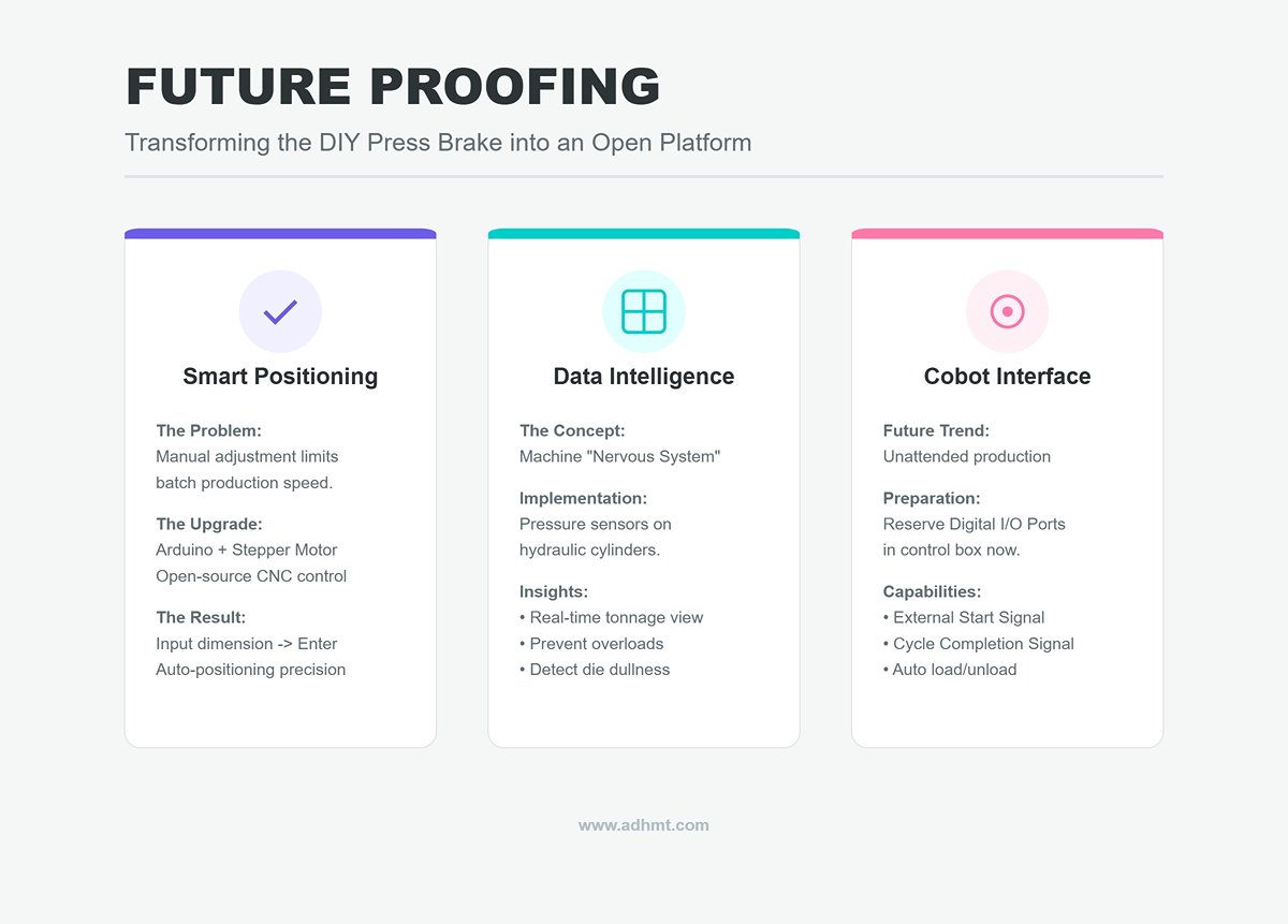
This machine should not be a closed end product but an open platform. As your business grows, it should be ready to integrate with modern industrial automation.
- Transition from Manual to CNC Backgauge: When your production shifts from single pieces to small batches (10–100 units), manual backgauge adjustment will become a bottleneck.
- Upgrade Path: Use an Arduino or Raspberry Pi to control a stepper motor driving a ball screw, replacing the manual screw adjustment. Combined with open-source CNC control software, you can achieve a semi-automated process where you simply input the dimension, press Enter, and the backgauge positions itself automatically. This brings not just an efficiency boost but a leap in precision.
- Digital Interface Provision: The factory of the future is data-driven. Even now, you can equip your machine with “nervous system endpoints.”
- Implementation Plan: Install a pressure sensor on the hydraulic cylinder and connect it to a digital display. This allows real-time tonnage monitoring to prevent overloads. Over time, the accumulated data can also help analyze tooling wear—if the required pressure for the same material suddenly increases, it likely indicates die dullness.
- Collaborative Robot (Cobot) Interface Preparation: While it may sound futuristic, integrating a cobot for automatic loading and unloading is already becoming an industry trend.
- Forward-Thinking Design: When designing the electrical control box, reserve a set of digital I/O ports (e.g., external start, cycle completion signal). In the future, when you decide to introduce a robotic arm for fully unattended production, your DIY press brake can integrate seamlessly into an automated cell—evolving from a standalone machine into a flexible manufacturing unit.
VII. Conclusion
How to make a small press brake is far more than a mechanical assembly task; it is a systematic engineering challenge that demands precision, craftsmanship, and strategic foresight. From the panoramic analysis of ROI to the rigorous control of core mechanics, and from the material wisdom of selecting S355MC high-strength steel to the micron-level precision of fiber laser cutting, every step determines the final outcome.
We have unveiled the "invisible barriers" often overlooked—the physical truths of crowning compensation, the necessary rituals of stress relief, and the future-proof layout for automation interfaces. Whether you are a DIY enthusiast pursuing ultimate cost-performance or a precision sheet metal expert seeking high-margin returns, this guide provides a clear roadmap to transition from "rough growth" to "master-level smart manufacturing."
For those seeking deeper industrial insights and professional-grade solutions, exploring ADH Machine Tool can offer valuable technical resources and real-world applications. True industrial-grade precision should not remain on paper.
If you are ready to transform these "master-level" techniques into actual productivity on your shop floor, or if you are looking for a finished machine that perfectly integrates all the engineering wisdom discussed above, do not hesitate to contact us and start your journey toward smarter manufacturing.


