I. Introduction
A press brake is a machine tool used in metal forming to bend and shape metal sheets. These machines are widely utilized in industries such as construction, automobile, aerospace, and others involved in sheet metal processing and manufacturing. To achieve optimal performance in these sectors, many manufacturers now adopt advanced CNC Press Brake systems that ensure higher precision and flexibility.
However, the key to achieving high-quality and efficient bending lies not only in the machine's performance but also in the tools it uses—press brake tools. These tools are the heart of precise bending, directly impacting the accuracy of the formed workpieces, processing flexibility, and overall productivity. To further enhance performance, operators can explore Mastering Press Brake Accessories to understand how complementary components improve efficiency and precision.
The press brake tool is comprised of two parts: the upper die (punch) and the lower die. The combination of these two dies, with their different shapes, acts upon the plate to form workpieces of various shapes.
Ⅱ. Cognitive Reconstruction: Building a Systematic Understanding of Bending Dies
Within the sheet metal industry, a dangerous misconception is widespread: managers are often willing to invest millions in top-tier press brakes, yet hesitate to allocate a fraction of that budget to high-quality tooling. This entrenched mindset—valuing machines over dies—is the root cause of many factories’ capacity bottlenecks and quality instability. Before diving into technical details, we must first reconstruct our perception.
2.1 Redefining the Value of Dies: The Logic Behind the “Tooling First” Philosophy
Machines determine the ceiling of production capacity; dies define the floor of product quality and profitability.
If the press brake is a pistol, the die is the bullet. The gun’s performance determines range and stability, but the bullet’s precision and power decide whether the target is hit effectively. On the production floor, this analogy becomes brutally real:
- Machine parameters (such as number of axes, tonnage, and open height) define the physical boundaries of what jobs you can take;
- Die performance (accuracy, interchangeability, wear resistance) determines how much profit you can actually retain from those jobs.
Why should high-quality dies be viewed as assets rather than consumables? Traditionally, dies were considered expendable—use them until they wear out, then replace them. In modern lean manufacturing, however, high-precision tooling should be treated as fixed assets. Let’s break down the hidden economics: a low-cost die might save you 30% upfront, but with a loose tolerance band (say ±0.05mm), operators spend up to 30 minutes shimming and leveling during every die change. Each batch may also require 3–5 trial bends to achieve the correct angle. In contrast, a precision-ground die with ±0.01mm tolerance can be installed and used immediately, delivering a first-piece pass rate from the start.
- Time savings: Over the course of a year, reduced setup and adjustment time alone can free up the equivalent capacity of an entire additional machine.
- Scrap reduction: Precision dies ensure bending consistency, dramatically lowering the risk of wasting expensive sheet material.
This defines the “Tooling First” investment philosophy: by investing in high-precision dies, you shift dependency from human skill (manual adjustment) to system precision (standardized accuracy).
If you wish to explore how to select suitable dies for your bending projects, refer to this comprehensive guide on Select Toolings for Press Brake.
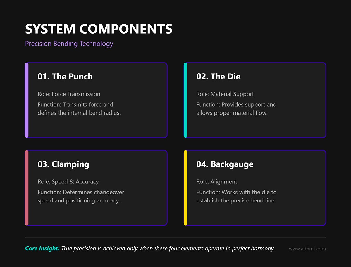
System Composition: More Than Just Punch and Die A die is not an isolated block of steel—it’s a precision system comprising four interdependent elements: the punch, which transmits force and defines the internal bend radius; the die, which provides support and allows material flow; the clamping system, which determines changeover speed and repeatable positioning accuracy; and the backgauge, which works with the die to establish the bend line. Only when these four elements operate in perfect harmony can true precision bending be achieved.
2.2 Mainstream Tang Systems and Compatibility Overview
When you walk into a workshop and face a wall of assorted dies, how can you instantly identify their system type and potential? Globally, three dominant systems prevail:
1. American Style (Traditional System)
- Identification features: Wide, flat tangs usually without locating grooves, clamped simply with plates and bolts.
- Characteristics: A design with a strong sense of history. Its key advantage is reversibility—the die can be mounted upside down. While robust and low-cost, suited for less demanding operations, it suffers from poor accuracy retention and very slow changeovers. Without an automatic centering mechanism, alignment depends heavily on the operator’s skill.
- Legacy asset management: For factories holding large inventories of American-style dies, this becomes a significant “negative asset” during automation upgrades, often the biggest obstacle to implementing automatic tool change systems.
2. European Style (Promecam System)
- Identification features: Narrow tangs with standardized locating grooves (Safety Tang), typically used with intermediate holders.
- Characteristics: Currently the most widely used system worldwide. Its core strengths are standardization and modularity. The segmented design (10mm, 15mm, 20mm… up to 100mm combinations) allows operators to assemble required lengths like building blocks. It offers far better positioning accuracy than the American style and benefits from a large ecosystem of third-party suppliers, delivering excellent cost performance.
3. Wila/Trumpf New Standard System
- Identification features: Standard 20mm-wide tang with complex dual-slot geometry; punches usually include Safety Click buttons or pins.
- Characteristics: The crown jewel of press brake tooling. It introduced the hydraulic quick-clamping revolution, combined with patented self-seating technology. A single button press automatically aligns and locks the entire tool row with micron-level precision.
- Application scenarios: For factories pursuing ultimate efficiency, frequent changeovers, or robotic bending cells, this is the uncompromising choice. The Safety Click feature enables vertical tool installation and removal, significantly improving both safety and productivity.
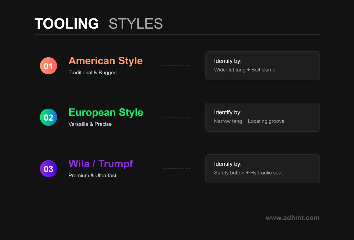
Quick Identification Guide:
- Wide flat tang + bolt clamp → American Style (traditional, rugged)
- Narrow tang + locating groove + segmented design → European Style (versatile, precise)
- Safety button + hydraulic seat → Wila/Trumpf (premium, ultra-fast)
If you’re considering upgrading to automated systems, explore the CNC Press Brake options that integrate seamlessly with modern tooling systems.
2.3 Material Science: The Metallurgical Code That Determines Die Longevity
Dies may look identical on the outside, but their internal crystalline structure determines whether they’re heirloom-grade tools or disposable components.
Material Showdown: 42CrMo4 vs. C45
- C45 (Standard Carbon Steel): The entry-level choice for dies. After quenching and tempering, it meets general requirements, but under high tonnage (e.g., stainless steel bending), it lacks compressive strength and is prone to plastic deformation.
- 42CrMo4 (Chromium-Molybdenum Alloy Steel): The gold standard for professional dies. Chromium (Cr) enhances hardness and corrosion resistance, while molybdenum (Mo) greatly improves toughness and through-hardening depth. Compared with C45, 42CrMo4 has a higher yield strength (around 700–900 MPa), meaning that under extreme pressure, C45 may deform permanently, whereas 42CrMo4 springs back to its original shape.
Hardening Process Insights: The Key to Regrindability A die must not only be hard—it must be hardened scientifically.
- Induction Hardening: Similar to boiling an egg—heated from the outside inward. Its advantages include a deep hardened layer (up to 3–4mm) and excellent toughness, enabling multiple deep regrinds over its lifetime. The trade-off is greater thermal distortion, requiring significant post-grinding correction.
- Laser Hardening: Precision Like a Scalpel
This method uses a high-energy laser beam to heat only an extremely thin surface layer (about 1 mm). The result is exceptional surface hardness (often exceeding 60 HRC) with virtually no thermal distortion, ensuring outstanding geometric accuracy. However, because the hardened layer is so thin, regrinding must be performed with extreme care—once this layer is ground through, the die is irreparably damaged.
Evolution of Coating Technologies: The Last Defense Against Adhesion
When processing galvanized or aluminum sheets, fine material particles can cold-weld under pressure to the die’s V-groove, forming built-up deposits that scratch subsequent workpieces.
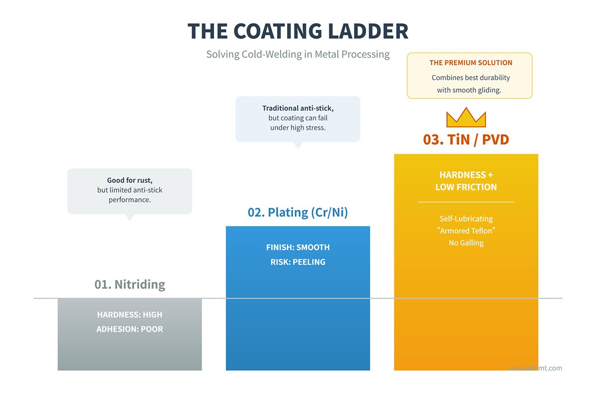
- Conventional Nitriding: Enhances surface hardness and provides moderate rust resistance, but its anti-adhesion performance is limited.
- Chrome/Nickel Plating: A traditional anti-sticking approach that offers a smooth finish, though the coating is prone to peeling under stress.
- TiN (Titanium Nitride) / PVD Coatings: A premium solution. These golden coatings combine exceptional hardness with an ultra-low friction coefficient, providing a self-lubricating surface. It’s as if the die were armored in a Teflon-like layer—allowing sheet metal to glide smoothly during bending and virtually eliminating galling and material buildup.
Ⅲ. Overview of Press Brake Tools and Accessories
3.1 Different Types of Press Brake Tools and Their Functions
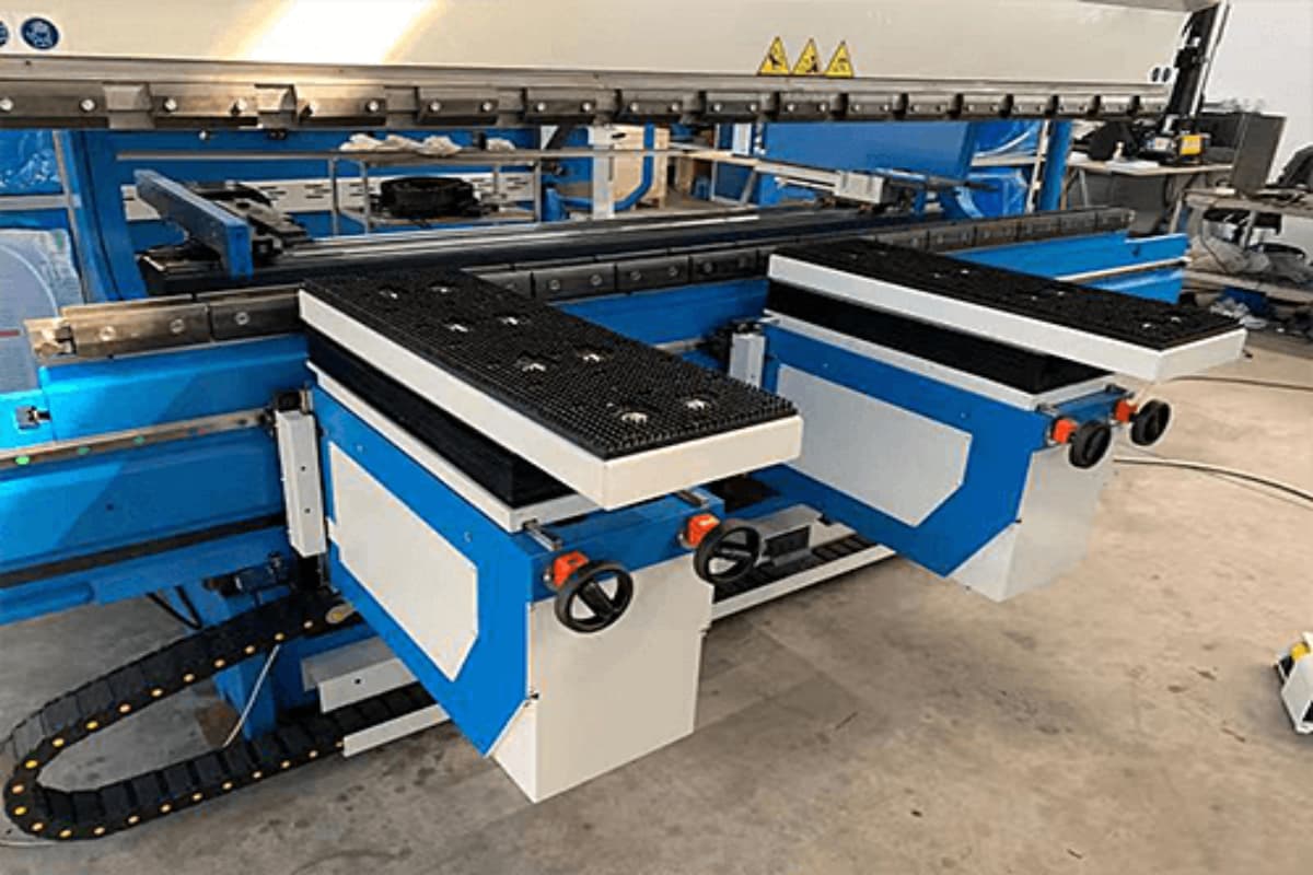
The components of a press brake include a conventional die assembly, an upper die (punch), and a V-shaped die. It is important to choose different press brake dies based on the type of metal sheet being used.
For instance, when working with metal plates that have high tensile strength, the die must also have a matching hardness to prevent damage to the die or incorrect bending of the metal sheet.
The conventional tooling group consists of an upper die and a lower die, which work together to bend the metal sheet. The punch is usually made of materials with high hardness to effectively extrude or cut the metal plates.
Similarly, the lower die requires a material of equal hardness since the punch will press the metal sheet into it. The upper die (punch) of the press brake can have special shapes and angles to produce workpieces with specific shapes.
These special punches include standard punches, gooseneck punches, sash punches, arrow punches, acute punches, and others.
Press brake dies are commonly made from hardened steel, such as chromium-molybdenum steel, to prevent punch cracking caused by excessive pressure or plate hardness. The use of materials with high hardness also helps ensure the durability of the punch.
The lower die of a press brake can be classified into four types: the V-shaped die, the U-shaped die, the single die, and the double die. The V-shaped and U-shaped dies are made of the same material as the punch and are known for their durability and high hardness.
The size of the opening in the V-shaped die affects the choice of bending radius for the workpiece and the method of bending. The lower die's groove is designed to fit the upper die, allowing the sheet to be securely fixed and molded into the final shape of the workpiece.
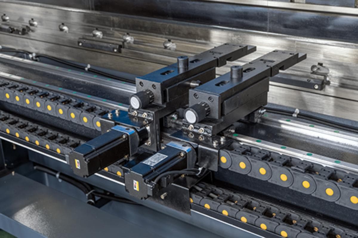
Punches and dies are the primary tools for press brake. In addition to these, the universal press brake also has other essential special press brake tools such as the back gauge, clamping tool, and support rack.
The proper calibration of these components is vital for precision; learning How to Adjust the Backgauge Deviation on a Press Brake is a great starting point for operators seeking to improve their skills.
Other components of the press brake work together to ensure accurate bending position, angle, and speed, resulting in improved accuracy and quality of the final workpiece, increased productivity, and reduces operator fatigue.
3.2 Using High Quality Press Brakes Bending Tools and Accessories
The significance of using high-quality press brake punches dies, and accessories are obvious. These components can improve the precision of parts by providing precise press brake dies and other accessories.
The punch and die material should be sturdy enough to withstand wear and breakage. Quality tooling materials can also extend the lifespan of the tool and prevent deformation.
High-quality tooling ensures the quality of the bent workpiece, reducing errors in the final product. This, in turn, improves press brake production efficiency and reduces production costs.
Dies with a high level of matching and quality are highly effective in sheet bending. Advanced and high-quality accessories can enhance bending speed, accuracy, and final product quality.
For instance, accurate positioning of the backgauge and each axis can enhance the accuracy of the flange length and size of the workpiece. Quality hydraulic devices can provide consistent stroke and eliminate bending angles caused by inconsistent speed.
By using high-quality tooling and accessories, the bending quality of the press brake is ensured and the machine's lifespan is extended. This results in guaranteed product quality, improved production efficiency, and reduced production costs.
Ⅳ. Common Press Brake Tools and Accessories
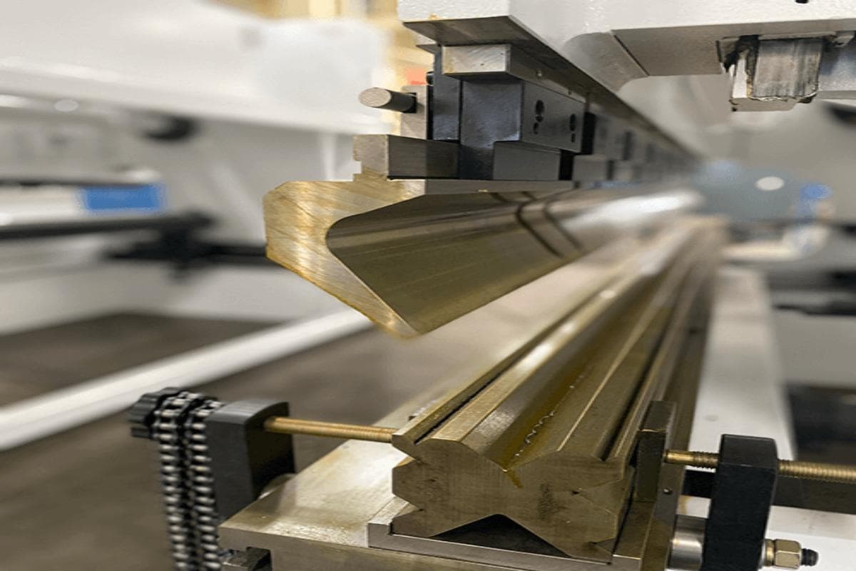
4.1 Press Brake Dies and Punches
The press brake die is divided into two parts, the upper die and the lower die, which work together to bend the sheet metal. The upper die can be further divided into various types of bending dies such as right angle, acute angle, obtuse angle, gooseneck die, standard die, and others.
The lower die, on the other hand, consists of different types such as the V-shaped die, U-shaped dies, single groove die, and double groove die. The upper die, powered by the ram, presses the metal sheet into the lower die, shaping it into the desired form. The die is typically made of high-hardness steel to prevent breakage.
Here is the detailed information on the specifications of different types of punch tools and die tools used in press brake operations:
Punches
| Type | Dimensions (mm) | Material | Hardness (HRC) | Suitable Metal Thickness (mm) | Remarks |
| Standard Punch | 835x130x26 | 42CrMo4 | 52-58 | 0.5-6 | Commonly used for 90°bending, weight 12kg |
| Acute Angle Punch | 835x97x26 | 42CrMo4 | 47±3 | 0.5-6 | Suitable for acute angle bending, weight 10.5kg |
| Gooseneck Punch | 835x120x56 | 42CrMo4 | 47±3 | 6-12 | Avoids workpiece interference, weight 13kg |
| Radius Punch | 835x145x32 | 42CrMo4 | 47±3 | 6-12 | Used for radius bending, weight 13.3kg |
| Z-Shape Punch | 835x197x92 | 42CrMo4 | 47±3 | 12-20 | Used for Z-shape bending, weight 15kg |
Dies
| Type | Dimensions (mm) | Material | Hardness (HRC) | Suitable Metal Thickness (mm) | Remarks |
| Single V Die | 835x116x26 | 42CrMo4 | 47±3 | 0.5-6 | Commonly used for right-angle bending, weight 13kg |
| Double V Die | 835x97x26 | 42CrMo4 | 47±3 | 0.5-6 | Suitable for multi-angle bending, weight 10.5kg |
| Multi V Die | 835x120x56 | 42CrMo4 | 47±3 | 6-12 | Multiple V-groove sizes, weight 13kg |
| U-Shape Die | 835x145x32 | 42CrMo4 | 47±3 | 6-12 | Used for U-shape bending, weight 13.3kg |
| Four-Way Die | 835x197x92 | 42CrMo4 | 47±3 | 12-20 | Four different groove sizes, weight 15kg |
- Material: 42CrMo4 is a high-strength alloy steel known for its excellent mechanical properties and wear resistance.
- Hardness: The hardness of 42CrMo4 typically ranges from 47 to 58 HRC, depending on the heat treatment process.
- Suitable Metal Thickness: The design of punches and dies is suitable for different thicknesses of metal sheets, typically ranging from 0.5mm to 20mm.
- Dimensions: Standard lengths are 835mm, with segmented lengths of 415mm available to fit different workbench sizes.
- Weight: The weight of different types of tools ranges from 10.5kg to 15kg, depending on the size and design of the tool.
4.2 Angle Gauges and Protractors for Measuring Bend Angles
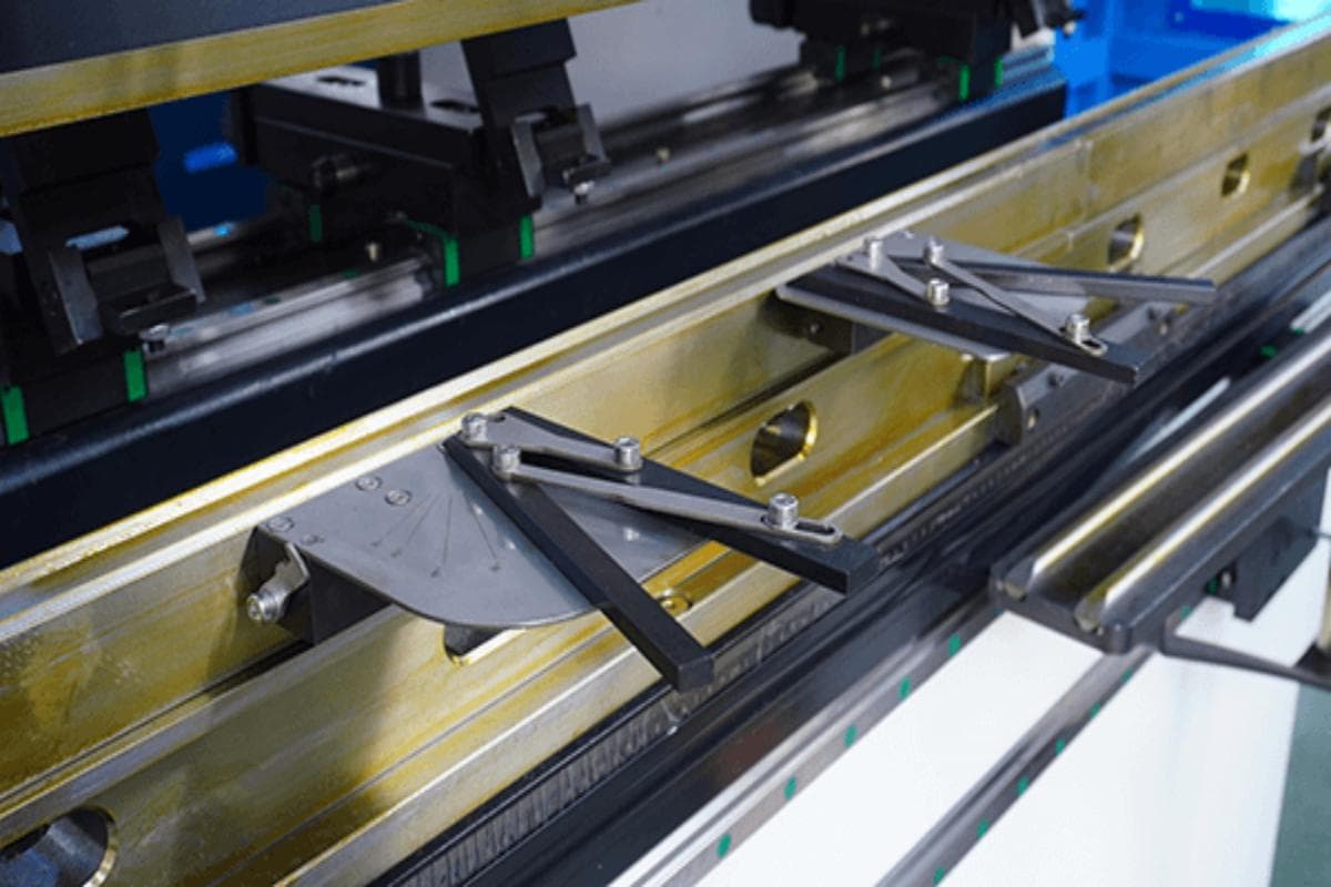
When bending metal plates, the tools used to measure the bending angle are referred to as angle gauges and protractor. Press brake punches and dies are used to shape the metal sheets into various angles and forms.
To guarantee the precision of the bending angle, angle gauges, and protractors can be employed. Correct the bending angle and verify its accuracy by using the angle gauges and protractor. There are various kinds of angle gauges and protractors, typically made of steel for support.
4.3 Press Brake Tools Lubrication
The utilization of lubricants can reduce wear and tear caused by long-term use of the press brake dies and components. The lubricants used for the press brake consist of cutting oil, grease, and wax. Lubricants can enhance the bending efficiency and prolong the lifespan of the press brake.
4.4 Safety Protection Devices
To protect the operator from any harm during bending, the press brake must be equipped with safety and protective devices. Such safety protection devices include protective fences, gloves, and other personal protective equipment.
Additionally, there are specialized protective devices installed on the press brake's operating parts. The press brake's brake caliper is fitted with a guard plate, which acts as a thermal braking component. Contact with this component may result in injury to the operator.
Ⅴ. In-Depth Principles: Mechanics Behind Bending Processes and Geometries
If the first chapter was about “choosing your weapon,” this one focuses on mastering the “inner technique.” Experienced operators know that bending isn’t just about brute force—it’s a delicate contest between internal stress release and the controlled plastic flow of metal. Understanding this physical interplay is the key to preventing defects and accidents at their root.
5.1 The Logic and Tool Matching of the Three Primary Bending Methods
Bending a sheet is not merely about applying pressure; it’s about selecting among three distinct mechanical modes depending on the required precision, tonnage, and workpiece characteristics.
- Air Bending: The Flexibility of Controlled Force
This is the dominant mode in modern CNC press brakes (over 90% of applications). Its core principle is three-point loading: the sheet contacts only the punch tip and the two shoulders of the die, without touching the die bottom.- Process Advantages: Extremely high flexibility. A single 85° or 88° tool set can produce angles anywhere between 90° and 180° simply by adjusting the punch stroke (Y-axis depth).
- Mechanical Trade-Off: Because the sheet is unsupported in the middle, elastic recovery (springback) is significant—typically 3°–5° for mild steel and even more for high-strength materials. This demands precise springback compensation algorithms in the CNC system.
- Tool Matching: The punch angle need not perfectly match the final workpiece angle, but it must be equal to or smaller than the target angle minus expected springback.
- Bottoming: Precision Through Physical Constraint
Here, the punch forces the sheet to conform fully to the V-die’s flanks until it makes complete contact. Required tonnage is typically 2–3 times that of air bending.- Core Principle: Forced contact minimizes springback uncertainty. While the neutral axis retains some elasticity, dimensional consistency improves dramatically.
- Best Suited For: Medium production runs demanding high angular consistency but without the extreme tonnage of coining.
- Tool Matching: The die angle must closely match the final bend angle (typically 88° or 90°), and the V-opening width must be precisely calculated.
- Coining: Destructive Precision
This is the “nuclear option” of bending, requiring 5–30 times the tonnage of air bending. It uses immense pressure to crush the neutral axis, forcing metal crystals to slip and fill microscopic gaps at the die bottom.- Process Characteristics: Virtually zero springback, extremely sharp internal radii (approaching the punch tip radius), and over 10% thickness reduction at the bend line.
- Current Status: Due to its severe impact on both machine and die life, coining is now rare—reserved mainly for aerospace, medical, and other zero-tolerance applications.
- Caution: Never attempt coining without verifying the die’s rated load capacity (typically requiring D2/M4 hardened steel with TiCN coating). Exceeding limits can easily shatter the die.
5.2 Functional Interpretation of Upper Die Geometries
Choosing an upper die shape is essentially a trade-off between strength and clearance. Every groove and cutout is engineered to solve a specific geometric interference challenge.
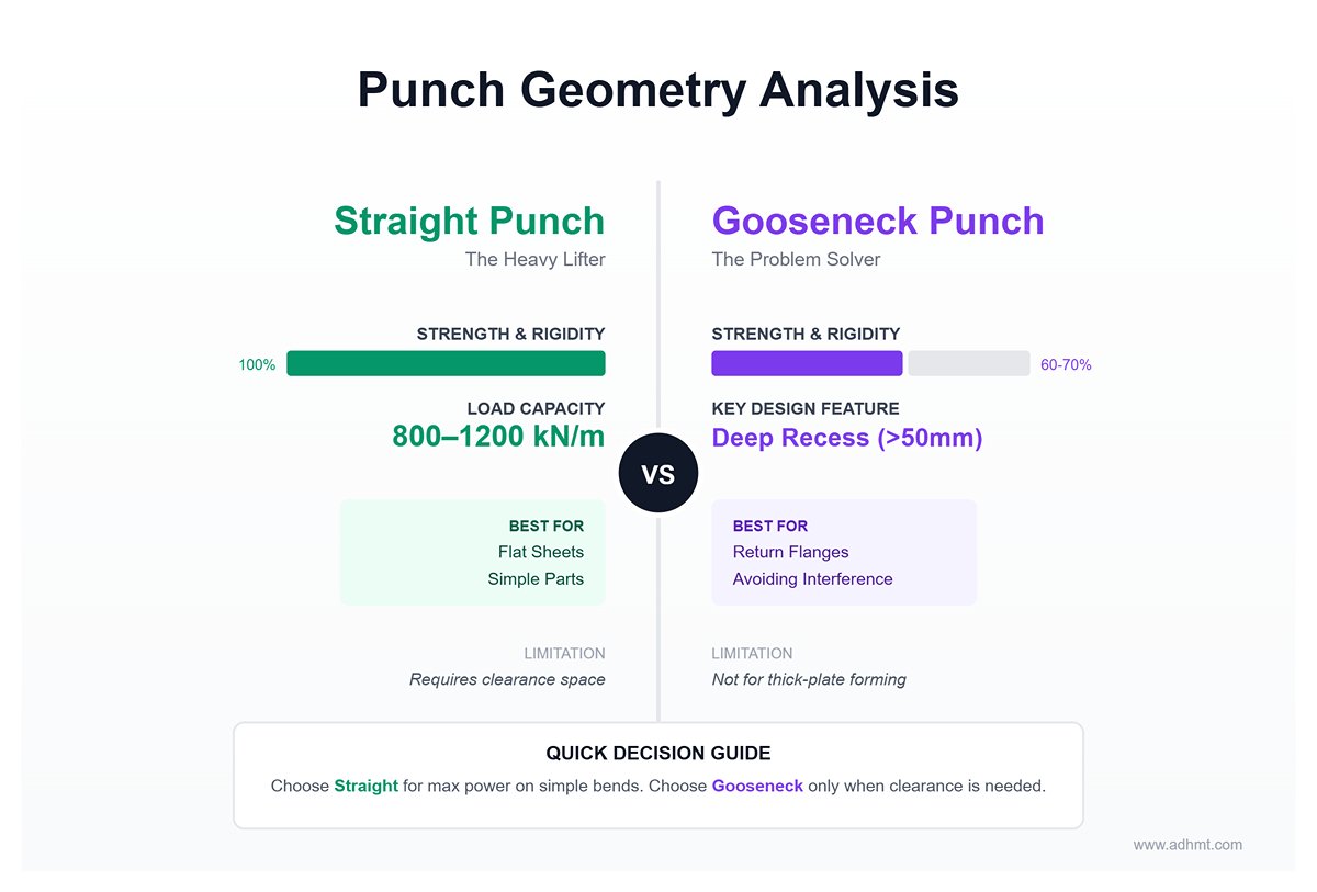
- Straight Punch vs. Gooseneck Punch
- Straight Punch: Features a solid cross-section and maximum rigidity, with load capacities typically between 800–1200 kN/m. Ideal for flat sheets and simple parts, but unsuitable for deep-channel or return-flange geometries where clearance is required.
- Gooseneck Punch: Designed specifically to avoid interference with return flanges. Its deeply recessed profile (neck curvature radius > 50 mm) allows the flange to swing past the punch body. The trade-off is reduced strength, with load capacity about 60–70% that of a straight punch—hence, it must not be used for thick-plate forming.
- Acute vs. Standard Punches: Managing Springback
- Acute Punch (30°–60°): Not just for sharp angles—when working with high-springback materials like stainless or spring steel, achieving a 90° result may require pressing to 80° or less. Only an acute punch provides enough clearance for such over-bending.
- Risk Factor: The acute punch tip is extremely fragile (often with R < 0.5 mm) and can chip easily when bending thick plates.
- Window Calculation: Precision Over Guesswork
How can you tell whether a complex workpiece will collide with the machine or tooling? Don’t rely on intuition—calculate it. Empirical Formula: Window Height ≈ Flange Depth × 1.7 + Punch Tip Offset.
This ensures that as the part lifts during bending, it clears the ram and backgauge safely throughout the sequence.
5.3 The Science of the Lower Die V-Groove
The V-groove does more than support the sheet—it governs bending force, internal radius (IR), and surface quality.
- The Relationship Between V-Width and Sheet Thickness (t)
- The Classic “8× Rule”: V = 8t. This golden ratio, ideal for mild steel under 12 mm thick, balances bending force and precision.
- Contextual Adjustments:
- High-Strength Steel / Thick Plates: Recommended V = 10t – 12t. Though this increases the internal radius, it significantly reduces tonnage demand and prevents outer cracking or die failure.
- Thin sheet / short edge: Adjust to V = 6t. This yields a smaller inner radius, but significantly increases the required tonnage and deepens surface impressions on the material.
- R-radius impact: the overlooked detail The shoulder radius of the lower die serves as the “entry point” for the sheet metal as it flows into the V-opening.
- Small R-radius: Provides strong grip but creates high frictional resistance, demanding greater tonnage and often leaving deep drag marks on aluminum or polished stainless-steel surfaces.
- Large R-radius: Reduces friction and surface scratches, but if excessively large, the sheet may slip during the initial bending stage, resulting in inconsistent dimensions.
- Special solution: Wing bending die For high-end applications such as home appliances or curtain wall panels where flawless appearance is critical, the sliding friction of a conventional V-die is a major cause of scratches. The wing-style die replaces fixed V shoulders with a pair of rotating rollers. During bending, the contact between sheet and die becomes “rolling friction”, similar to the principle of bearings.
- Value: Reduces friction by more than 70%, completely prevents surface scratches, and eliminates the need for costly polyurethane protection films. Although the die costs over three times that of a standard V-die, the savings in polishing labor typically offset the investment within six months.
Ⅵ. Practical Selection: Building a Zero-Error Decision Model
On the shop floor, relying on intuition is often the root cause of accidents and scrap. Many operators depend on past experience for die selection—a habit that might have worked in low-end processing but becomes pure guesswork when dealing with high-strength steels, tight tolerances, or complex geometries. This chapter aims to replace such uncertainty with quantifiable science through precise mathematical calculations and clearly defined boundaries, establishing a standardized model for tool selection and risk control.
6.1 Core Parameter Calculation and Safety Margin Definition
The first step toward a zero-error model is making every decision data-driven—particularly through accurate control of tonnage and springback.
Tonnage calculation formula (with tensile strength correction) The textbook formula applies mainly to mild carbon steel. In practice, a correction factor K must be introduced to account for different material tensile strengths—this is the first iron rule of bending calculations:
- P: Bending force (kN)
- S: Material thickness (mm)
- L: Bending length (m)
- V: Die opening width (mm) (standard recommendation: V = 8S–10S)
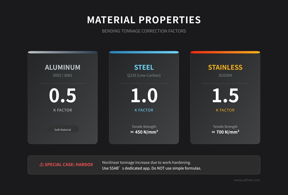
- K (Material correction factor):
- Aluminum (5052/6061): K ≈ 0.5
- Low-carbon steel (Q235): K = 1.0 (sigmab ≈ 450 N/mm2)
- Stainless steel (SUS304): K = 1.5 (sigmab ≈ 700 N/mm2)
- Expert tip: For wear-resistant steels such as Hardox, the work-hardening effect causes a nonlinear increase in tonnage. Never rely on simple formulas—always refer to SSAB’s dedicated calculation app for accurate data.
Load limit evaluation: differentiating between “indentation” and “catastrophic fracture” Two safety thresholds must be clearly defined. The commonly cited 1.5× safety factor of a die does not justify overload—it merely indicates the physical fracture limit.
- Safe zone: Working tonnage ≤ rated capacity × 0.8. Continuous operation within this range ensures no fatigue deformation.
- Damage zone: Working tonnage > rated capacity. The die shoulders will experience permanent plastic deformation (indentation), leading to irreversible accuracy loss.
- Rupture zone: Working tonnage ≥ rated capacity × 1.5. This is a critical red line—the die may shatter instantly, sending fragments flying and posing severe safety hazards.
Springback compensation strategy: the 88° vs 85° decision tree The harder the material, the greater the springback. Always reserve enough “overbend” allowance during tool selection.
- Low-carbon steel / Aluminum: Minor springback (≈1–2°). Use 88° punches and dies; fine-tune via bottoming if needed.
- Stainless steel / High-strength steel: Significant springback (3–5° or more). Use 85° or even 80° dies. Apply air bending and adjust the ram depth (Y-axis) to compensate, rather than relying solely on die angle contact.
6.2 Precision Tool Selection Matrix by Working Condition
Different working conditions require specific die configurations—there is no one-die-fits-all solution. The following matrix outlines optimal options for four representative scenarios:
| Operating Scenario | Recommended Die Solution | Key Technical Points (Key Tech) |
|---|---|---|
| Thin Sheets & Appearance Parts (SUS Mirror Panels / Aluminum Sheets) | Mark-Free Bending Solution | 1. Urethane Film: Placed over the V-groove to prevent direct metal contact, completely eliminating scratches. 2. Roller V-Die (Wing Bending): The shoulders of the lower die are equipped with rotatable rollers that convert sliding friction into rolling friction, removing surface drag marks. |
| Thick Plates & High-Strength Steel (>6mm Hardox) | Heavy-Duty Die | 1. Large R Radius Upper Die: The tip radius R must be ≥ sheet thickness to prevent the upper die from cutting into the material and causing fractures. 2. High Toughness Material: Use dies made of 42CrMo steel with cryogenic treatment (HRC 50+), effectively preventing edge chipping. |
| Complex Profiles / Deep Boxes | Gooseneck Die | Specially designed for “return-type” bends. The recessed notch allows clearance for previously formed flanges. During selection, ensure the die’s throat depth exceeds the flange height of the workpiece. |
| Hemming (Edge Flattening) | Sharp-Angle + Flattening Combination | Modern high-efficiency solutions recommend pneumatic hemming dies or spring-assisted dies, enabling 30° pre-bending and flattening in a single setup—boosting productivity by over 50%. |
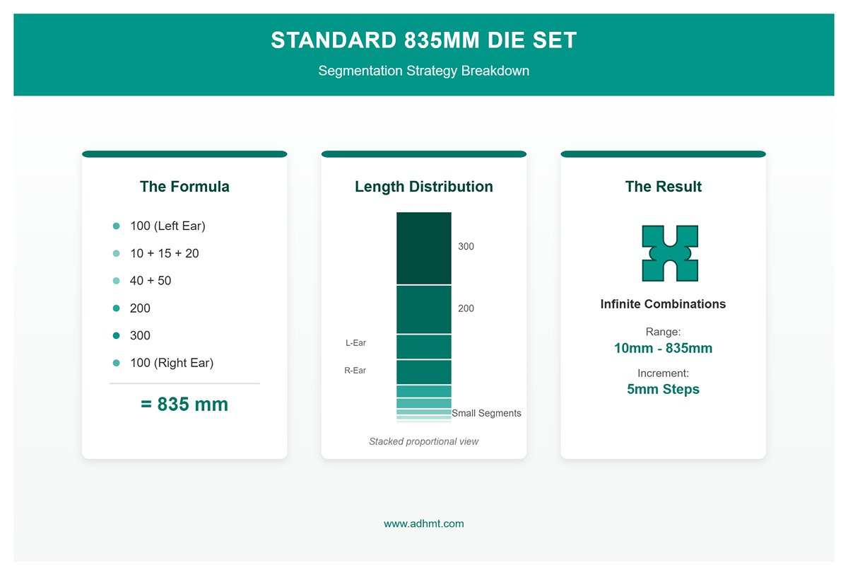
Segmented Die Configuration: The Optimal Combination
To accommodate workpieces of any length, a standard 835 mm die set should adopt a “golden ratio” segmentation strategy. Recommended standard combination:
100(left ear) + 10 + 15 + 20 + 40 + 50 + 200 + 300 + 100(right ear) = 835 mm.
With this modular setup, you can assemble any length from 10 mm to 835 mm in 5 mm increments—just like building with LEGO bricks.
Practical tip: Always keep two complete segmented sets on hand, so you can handle “U‑shaped” bends where both ends require clearance simultaneously.
6.3 Five Critical Checkpoints to Avoid Selection Pitfalls
Right before pressing the start button, make sure to go through the following five checkpoints. They are your last line of defense against tool collisions and die breakage.
- Clearance Verification (Collision Check)
Bending is not a static process. For deep box parts, you must calculate the swing height of the workpiece. Confirm that during upward movement, the part will not collide with the punch holder, beam, or backgauge. If clearance is insufficient, switch to a straight punch or use a taller die. - Tonnage Limit Verification
This is a commonly overlooked blind spot. Never apply full machine tonnage on a short die section.
Formula: Die load capacity (T/m)×current die length (m)>current set pressure.
Example: If a die is rated for 100 T/m and you’re only using a 0.1 m segment, the maximum allowable pressure is 10 T. If the press is set to 20 T, the die will inevitably fail. - Minimum Flange Length
If the flange is too short, the sheet may slip into the V‑groove, ruining the part or even ejecting it dangerously.
Quick rule of thumb: for a 90° bend, the minimum flange length $b_{min} \approx 0.7 \times V$. If the design length is smaller, switch to a narrower V‑groove (which increases tonnage) or add shims to the backgauge for support. - Origin Calibration Trap
Never use short die segments (10 mm or 20 mm) to calibrate the machine origin. Doing so concentrates pressure locally and can permanently dent the table surface.
Rule: Always use upper and lower dies at least 300 mm long for alignment, and limit pressure to 10–15% of the machine’s maximum tonnage. - R‑Radius vs. Material Thickness Interference
When selecting a larger V‑groove to reduce tonnage, the internal bend radius naturally increases (R≈V/6). Check whether this radius interferes with nearby holes or slots. If interference occurs, consider using a smaller V‑groove (with higher tonnage) or adjust the machining sequence.
Ⅶ. Operational Excellence: From Setup to Process Optimization
If die selection is the strategic planning stage, then operation is the front‑line battlefield. At this stage, even micrometer‑level installation errors or tiny process oversights can be magnified by hundreds of tons of pressure—leading to scrapped parts or even equipment damage. This chapter shifts the focus from the design office to the workshop floor, revealing the operational details that separate skilled operators from true process masters.
7.1 Quick Die Change (SMED) and Precision Calibration
In modern sheet‑metal production, downtime for die changes is the greatest efficiency killer. Studies show that up to 80% of workshop time is spent on changeovers and adjustments, with only 20% on actual production. Achieving SMED (Single‑Minute Exchange of Die) is not just about speed—it’s about establishing a standardized Zero‑Setup workflow.
- Standardized Installation SOP: Cleanliness Is the Foundation of Accuracy
This step is often overlooked but absolutely critical. Even a 0.05 mm metal chip or a spot of hardened grease can embed itself into the table surface under tons of pressure, permanently compromising accuracy.- Deep Cleaning: Before installation, thoroughly wipe the punch holder, ram underside, and die seat using non‑woven cloth.
- Pre‑Alignment: Never tighten the dies immediately. Mount them loosely, then lower the ram slowly until the punch tip just enters the V‑groove (without touching the bottom). This allows the V‑groove geometry to self‑center the die before final tightening.
- Origin Calibration Danger Zone: Never calibrate the machine origin using segmented dies shorter than 300 mm. Short dies under high pressure act like chisels, causing local dents. Always calibrate using full‑length dies, with pressure limited to 10–15% of maximum tonnage.
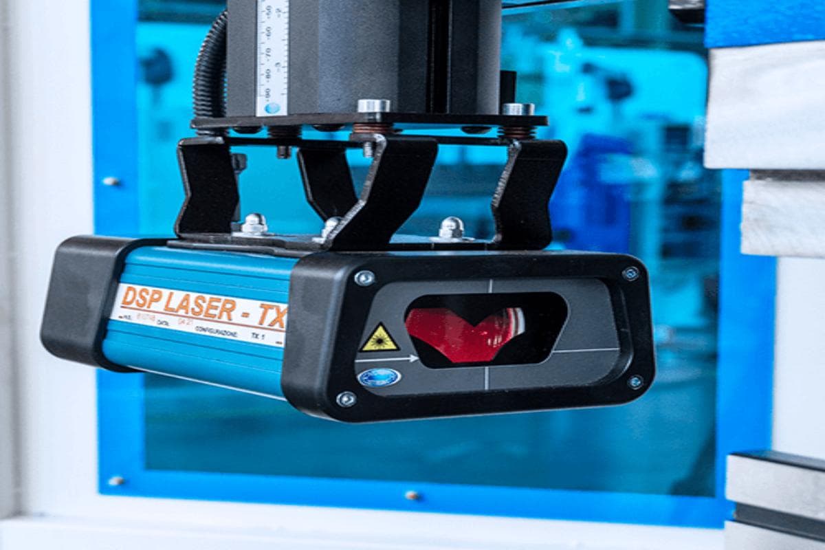
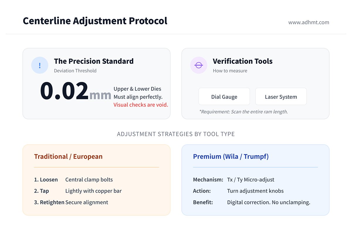
- Centerline Adjustment: The 0.02 mm Threshold
“Looks straight” is not good enough. The alignment deviation between upper and lower dies must be within 0.02 mm.- Verification Method: Skip visual checks—use a dial gauge or laser alignment system to scan the entire ram length.
- Adjustment Strategy: For traditional European‑style dies, loosen the central clamp bolts and tap lightly with a copper bar for fine tuning. For premium systems such as Wila or Trumpf with Tx/Ty micro‑adjust mechanisms, alignment can be corrected digitally via adjustment knobs—no unclamping required. This precision is what justifies the higher cost of advanced tooling.
- Error‑Proofing Innovation: The “Safety Click” Revolution
Modern precision dies (e.g., New Standard series) incorporate a mechanical spring‑lock mechanism called Safety Click at the tang. When inserted vertically into the clamp, the lock automatically snaps into place. This design enhances both safety and efficiency: it enables vertical loading and unloading, eliminating the need to slide dies in from the side. The result is a 90% reduction in changeover distance and the complete elimination of hand‑crushing hazards from falling dies.
7.2 Diagnosing and Eliminating Common Bending Defects
Defects never occur without cause—each has a physical explanation. Mastering diagnostic logic is the key to precise and effective troubleshooting.
Inconsistent Angles: Combating the Canoe Effect
- Symptom: After bending a long workpiece, both ends measure correctly (e.g., 90°), but the center is under‑bent (e.g., 92°). The piece appears wider in the middle and narrower at the ends—resembling a canoe.
- Root Cause: This is a matter of physics. Under load, the ram and lower table elastically deflect like a beam, increasing the die gap at the center compared with the ends.
Solution — Crowning Compensation:
- Mechanical Compensation: By adjusting the movement of wedge blocks inside the press bed, the center section is intentionally raised to counteract the elastic deflection caused by load.
- Diagnostic Technique: Excessive compensation results in a reverse camber—an overbend of around 88° in the center while both ends remain at 90°. If the press lacks automatic crowning, one may temporarily insert paper shims under the die seat as an emergency fix. However, this is an uncontrolled and unreliable workaround, not suitable for routine use.
Surface Indentation: The Invisible Micron-Level Killer
- Root Cause Analysis: What’s often mistaken for “tool roughness” is actually metal galling (cold welding). When processing galvanized sheets, zinc particles can detach under high pressure and cold-weld onto the shoulders of the V-die. These microscopic deposits, barely visible to the naked eye, act like sandpaper and scratch subsequent stainless-steel parts.
- Elimination Strategy:
- Physical Isolation: For mirror-finish stainless steel, always use a 0.5 mm urethane protective film on top of the V-die to prevent direct contact.
- Process Upgrade: Switch to a roller-type V-die (Wing Bending), converting sliding friction into rolling friction and fundamentally removing the conditions that cause surface scratches.
Hole Distortion: The Threefold Stress Flow Principle
- Mechanism: The metal near the bend line undergoes plastic flow and stretching. If a hole lies within this deformation zone, it will inevitably stretch into an oval shape.
- Critical Formula: The minimum distance from the hole edge to the bend line must satisfy Lmin ≥ 3 × T + R (where T is the sheet thickness and R is the inner bend radius).
- Remedial Measures: If design constraints prevent relocation, add relief slots or process holes along the bend line to interrupt stress transmission, or rearrange operations to perform bending first and hole expansion afterward.
7.3 Full Lifecycle Management of Tooling
A die is not just a block of steel—it’s a precision instrument. Its accuracy and service life depend entirely on how well it is managed.
Wear Identification: “Saddle Wear” Syndrome – This is the classic result of habitual operation. Many operators prefer bending short parts at the center of the press. Over time, the central section wears down (sometimes by 0.05 mm), while both ends remain pristine.
Consequence: When bending long parts later, the ends make contact first, leaving the center under-bent and impossible to correct.
Countermeasure: Implement a mandatory segmented usage strategy—divide the press into left, center, and right stations, and rotate short-part production among them according to a fixed schedule.
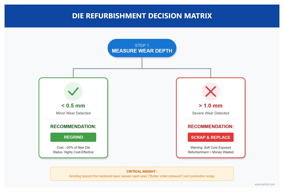
Refurbishment Economics: The “Death Line” of Laser-Hardened Layers – Not every die is worth regrinding. Precision dies, such as those made from laser-hardened 42CrMo steel, typically have a hardened layer only 1.5–3 mm deep. ROI Decision Guide:
- Minor Wear (<0.5 mm): Professional regrinding is recommended. The cost is only about 20% of a new die, making it highly cost-effective.
- Severe Wear (>1.0 mm): Exercise caution. Grinding beyond the hardened layer exposes the soft core, which wears rapidly—like butter under pressure. Refurbishment in this case wastes money and leads to quick precision loss and scrap production. Direct scrapping is the most economical choice.
Storage Environment Standards: 5S Fixed-Position Management – The greatest threat to dies isn’t pressure, but impact. If the working faces (V-grooves and punch tips) collide or rub during handling or storage, even tiny dents will imprint defects on every subsequent part.
- Absolute Prohibition: Never stack dies randomly on pallets.
- Standard Practice: Use vertical hanging racks or individual drawer-style cabinets to ensure dies never touch one another.
- Anti-Rust Maintenance: Unlike ordinary tools, the surface finish of bending dies directly affects product appearance. Keep humidity below 60%, and apply rust-preventive oil during long-term storage. Even minor fingerprint corrosion can change friction characteristics and alter bending angles.
Ⅷ. Advanced Applications: Special Scenarios and Cutting-Edge Technologies
If previous chapters focused on how to use dies correctly, this one explores how to break the rules intelligently. In high-end sheet metal fabrication, competition often happens at the boundaries where standard processes fail. True experts don’t just avoid risks—they exploit unique geometries and emerging smart technologies to achieve optimal results under seemingly impossible conditions. This chapter reveals the technical “black boxes” rarely discussed in manufacturers’ brochures and takes you to the physical limits and hidden costs of bending operations.
8.1 Special Forming Solutions for Complex Workpieces: Pushing the Boundaries of Physics
Ordinary operators focus on tonnage; process masters focus on interference. The key to solving complex forming challenges lies not in brute machine strength, but in cleverly “deceiving” geometry and physics to accomplish plastic deformation within tight spatial constraints.
Closed Frame Bending: The Battle Between Window and Horn Tooling
Deep box bending is one of the most frustrating challenges in structural part fabrication. To avoid collision with pre-bent side flanges, two main approaches exist—but both can lead to disaster if their mechanical limitations are misunderstood.
- Hidden Danger of Horn Dies: Many engineers assume that as long as the die has extended “horns” at both ends, deep box bending is unlimited.
- The Risk Reality: The cantilevered horn structure has very poor resistance to off-center loading. While the main die body may withstand up to 100T/m, the horn tips typically endure only 30–50% of that capacity.
- Operational Red Line: Never use bottoming operations at the horn tips—only light air bending is permitted. Overloading the tips can cause the tool steel to shatter like glass, sending fragments flying and posing a fatal risk to operators.
- Window Tooling: When horn length is insufficient for ultra-deep frames, a “window die” must be used.
- Design Logic: A rectangular window is cut directly into the upper die body, allowing the bent flange to pass through and completely eliminate geometric interference.
- Design Rule: The window height should exceed the flange height by at least 20 mm for safety clearance. Note that cutting a window reduces overall die rigidity by over 30%, so derated operation is mandatory.
Z-Shaped and Offset Bending: The Tonnage Multiplication Trap
Offset bending (Joggle) may look simple, but in reality it’s a complex process that combines two simultaneous 90° bends plus a powerful coining operation.
- Physics at work: The instantaneous tonnage required is typically five times higher than that of standard air bending.
- Case warning: Bending a 2 mm steel plate that’s 1 meter long takes just 15 tons with air bending. But forming a Z‑bend in one shot with an offset die can generate an impact force of 75–100 tons. If your press brake is rated at only 50 tons, this could lock up the hydraulic system—or worse, cause permanent deformation of the beam.
- The spring‑back curse: If the short middle flange of a Z‑bend isn’t fully coined flat, enormous residual stress will remain. For high‑tensile steel, a perfect Z‑shape is impossible unless you use a special offset die with a spring‑back compensation mechanism.
Hinges and Curling: The Golden Ratio for Preventing Fractures
Curling exposes the brittle side of high‑tensile steel. The typical failure mode is the propagation of micro‑cracks along the outer arc of the curl.
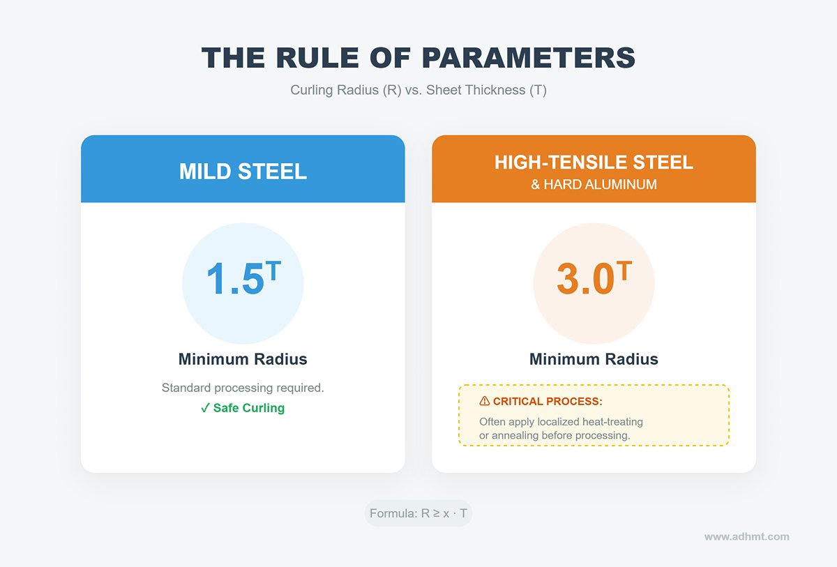
- The rule of parameters: The ratio between the curling radius (R) and the sheet thickness (T) determines success or failure.
- Mild steel: Safe curling can be achieved with R ≥ 1.5 T.
- High‑tensile steel / hard aluminum: Follow the R ≥ 3 T principle, and often apply localized heat‑treating or annealing before processing.
- Process workaround: When the design demands an extremely small curling radius, a proven trick is to imprint a tiny “pre‑stress mark” at the edge of the sheet. This disrupts the surface lattice structure and blocks the path where larger cracks would normally form.
8.2 Smart and Automated Trends: The Hidden Maintenance Costs Behind the Boom
In today’s so‑called “Industry 4.0” era, automation is often portrayed as the ultimate cure‑all for efficiency problems. But automation isn’t plug‑and‑play—it must be fed with both money and data.
Smart Tooling Technology: The Truth Behind Data Integration
Modern high‑end tooling—such as Wila or Trumpf premium series—comes with built‑in RFID chips or DM identification codes. These aren’t just for error prevention; their true value lies in the data logic behind the TIPS (Tool Identification and Positioning System).
- Overlooked function: The most valuable data stored in a smart chip isn’t how many times a tool has been used, but how much cumulative tonnage it has endured.
- Practical significance: One tool may have bent only 1,000 parts, but all at full load; another may have formed 10,000 parts under light load. The smart system will automatically retire the first one based on its “cumulative fatigue tonnage,” preventing catastrophic failure during production. This load‑based life management is the essence of preventive maintenance.
Automatic Tool Changer (ATC): The Costly “Helping Hand”
Equipment such as Amada HG‑ATC or Bystronic Xpert Pro can reduce tool‑change time from 30 minutes to just 2 minutes. For high‑mix, low‑volume (HMLV) workshops where setups change 10+ times a day, the ROI period is typically under 18 months. Yet behind the impressive efficiency lies a major maintenance burden.
- Gripper claws: These are the most fragile consumables in an ATC system. Continuous handling of heavy dies causes wear and, once friction drops, slippage can occur. A falling die may not only destroy itself but also damage costly robotic fingers or lower die holders.
- Cleaning costs: ATC systems have zero tolerance for dust. The traditional “air‑gun blow‑off” method is useless here; dedicated ultrasonic cleaning stations are required. Even tiny metal shavings lodged in the precision guide rails can halt the entire automation unit instantly.
Adjustable V‑Die: The Price of Precision
These are often seen as “magic tools.” CNC control allows continuous adjustment of V‑opening width—from V6 to V50—eliminating the frustration of missing the right V‑slot. Yet this flexibility comes at a cost.
- Uneven wear: Since adjustable V‑dies are assembled from two separate insert strips, long‑term use of small V‑openings causes excessive wear on the inner edges. When you later open a large V‑slot for long‑flange bending, two visible seam marks can appear on the workpiece surface.
- Insufficient rigidity: The modular structure can never match the stiffness of a solid die. When bending plates thicker than 6 mm, the base slightly “opens” elastically, increasing angular deviation. Operators therefore need advanced crowning compensation skills to correct for this deflection.
[Expert Advice] When adopting these advanced technologies, follow the 80/20 principle: invest 80% of your budget in high‑precision standard tooling and systems, and only 20% in specialized “black‑tech” solutions such as ATC or complex forming dies. In a future of constantly shifting orders, versatility often ensures survival better than extreme specialization.
Ⅸ. Purchasing and Maintenance Tips
9.1 Key Considerations When Selecting Press Brake Tools
Factors to Evaluate
- Material Thickness and Type
Material specifications greatly influence tooling selection. The thickness of the sheet metal determines the required V-die opening and punch radius. For example:- Thicker materials generally necessitate larger V-die openings to prevent cracking or excessive stress on the material.
- Thinner materials require tighter tolerances, making it imperative to select precision tools that minimize deformation or overbending.
- Harder materials like stainless steel require higher-grade tooling capable of withstanding increased bending pressure to avoid premature wear or damage.
- Softer materials like aluminum may necessitate specialized inserts or coatings to prevent surface scarring.
- Bending Angle and Radius
Each project requires specific bend angles and radii based on tool geometry and material behavior. Ensure the punch radius matches the internal bend radius to avoid cracking or deformation. For tighter bends, use low-radius tools. Consider tolerances for consistent results. - Tonnage Capacity of the Press Brake Machine
The machine's tonnage capacity must match the force needed for the tooling and material. Overloading with incorrect tools can cause failures or hazards. Use tonnage charts from manufacturers to calculate required tonnage based on material thickness, die width, and punch specifications. For applications near maximum tonnage, use high-strength tooling to reduce strain.
Standard vs. Custom Tooling
Tooling selection also involves a careful decision between standard and custom solutions, depending on the application scope and complexity.
- Benefits of Standardized Tooling for General Use
Standard tooling is widely available and cost-effective for common bending operations. Its modular design allows operators to adapt to a range of material types and bend geometries, making it suitable for general-purpose fabrications. Additionally, standardized tools are interchangeable and compatible with most machines, minimizing the need for extensive adjustments or downtime. - When and Why Custom Tooling is Required
Custom tooling becomes a necessity for unique or highly demanding applications that standard tools cannot address. These include:- Complex bend profiles requiring non-conventional punch or die shapes.
- Applications where tolerances are exceptionally tight.
- Projects that involve exotic materials or unique coatings.

9.2 Maintenance Tips to Extend Tool Life
Regular maintenance ensures consistent performance, minimizes downtime, and extends tooling life. Follow these essential practices to keep your tools in optimal condition:
Cleaning and Inspection
- Clean punches and dies daily to remove debris, oil, and metal shavings that cause wear.
- Check tooling for cracks, chips, or wear, and replace damaged tools immediately to maintain accuracy.
Lubrication and Alignment
- Lightly lubricate tooling surfaces to minimize friction and prevent rust.
- Routinely align punches and dies to avoid uneven bends and tool damage.
Safe Storage and Handling
- Keep punches and dies in dedicated cabinets to avoid damage.
- Handle tools carefully, using protective covers to prevent scratches or corrosion.
Operator Training
- Train operators in proper handling and maintenance to reduce errors and tool wear. Skilled operators can significantly prolong the life of your tooling and ensure consistent results.
9.3 Safety Precautions During Maintenance
- Always unplug the press brake before maintenance to prevent accidental activation.
- Use non-flammable cleaners and avoid standing on the machine to ensure safety. Following these precautions reduces the risk of accidents and keeps your workspace safe for all operators.
Ⅹ. Conclusion
This blog aims to introduce you to the common press brake tools and highlight the importance of using high-quality tools in metal fabrication. The wide range of press brake tooling used in a press brake machine includes press brake punches and dies, a backgauge, a protractor, a hydraulic device, and a protective device, among others.
High-quality press brake tools are an essential component of a top-performing press brake machine. In the long run, choosing a press brake with a moderate price but high quality can effectively reduce production costs.
ADH manufactures a wide variety of standard tools and special tools according to the needs of each client and boasts high quality, exceptional performance, and a cost-effective price. You can view our latest brochures for detailed product specifications or contact us directly for personalized recommendations and technical support.


