I. Introduction
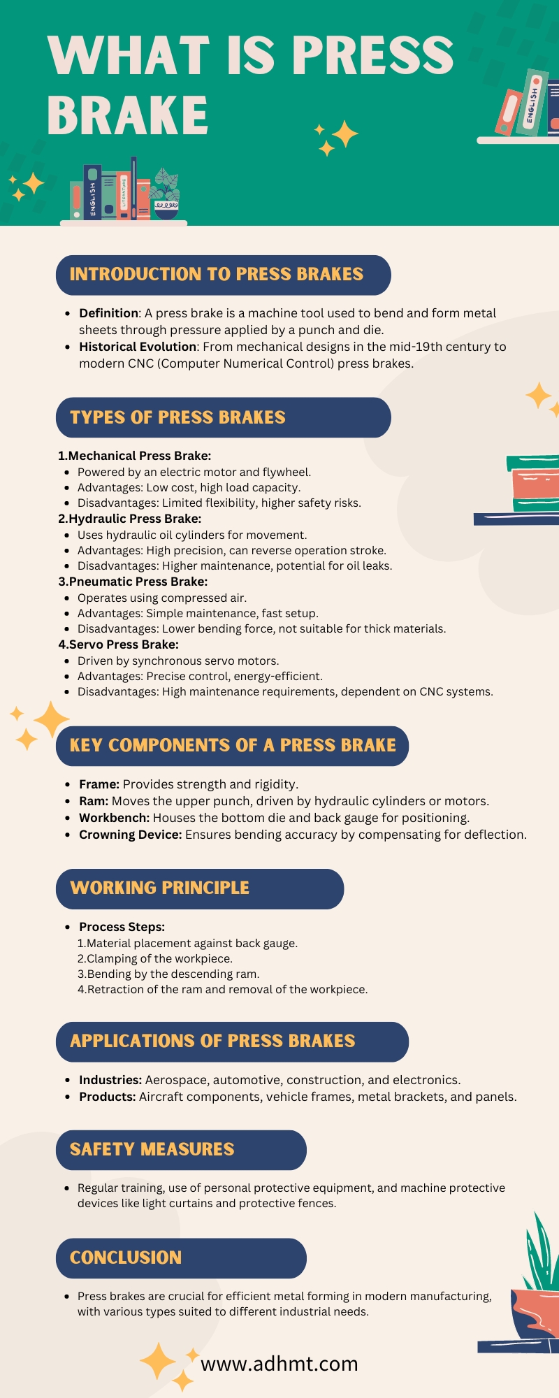
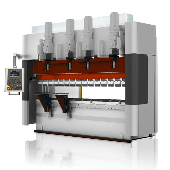
A press brake is a metal bending machine in the metal fabrication industry. It is mainly designed for the precise bending and forming of thin plate sheets. With the development of technology, from the mechanical press brake in the mid-19th century to the emergence of the electric press brake in the early 20th century and then to the introduction of computer numerical control technology, the function and efficiency of the press brake have significantly improved.
It can bend the sheet into various angles and improve processing accuracy and production efficiency via CNC functions. Our passage will deepen into the types, basic structures, working principles, usages, etc., to help you understand this bending machine tool more comprehensively. If you want to explore modern, high-precision bending equipment, you can check our CNC Press Brake series.
II. What Is Press Brake?
2.1 Definition
A press brake is a machine tool used for metal sheet processing. It exerts pressure on the metal sheet via the upper and bottom tools, causing plastic deformation and bending. The upper tool is usually named the punch, and the lower tool is called the die.
It is widely used in various industries, such as automobiles, aviation, electronics, and construction, which play a vital role in metal processing. For a deeper understanding of die and punch configurations, refer to the Guide to Press Brake Tooling and Bending.
2.2 Working Principle
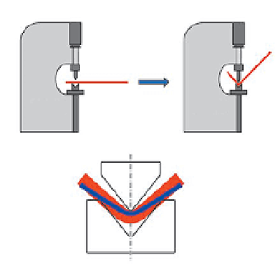
The basic working principle of a press brake is to utilize the upper punch and bottom dies to exert pressure on metal sheets. The metal sheet is placed in the V-shaped notch of the bottom die, and then the top punch descends, causing plastic deformation and forming along the V-shaped notch bending, thus acquiring the bending angle.
By changing the different shapes and sizes of tools, the press brake can process the workpiece with a variety of geometric shapes and angles. For large-scale bending tasks, you can refer to our Large Press Brake solutions designed for heavy-duty applications.
If you’re unsure which system suits your needs, consider exploring Hydraulic vs Electric Press Brake for tailored guidance on machine selection.
2.3 Main Structures
The press brake is mainly composed of a frame, ram, workbench, hydraulic system, etc. The frame supports the whole equipment and is made of a steel welded structure to ensure enough strength and rigidity. The ram is installed with an upper punch and moved by hydraulic cylinders.
The workbench is equipped with a bottom die and a back gauge device for positioning sheet metal. Moreover, the press brake is equipped with a crowning device, synchronization device, etc., to improve the bending accuracy.
2.4 Factors Affecting Bending Accuracy
The press brake produces precise bending in the workpiece through force, dies, and specialized tools. Factors such as toolings, material characteristics, bending radius, and bending methods can all affect bending accuracy.
According to machine design and specific bending application requirements, bending can be carried out through various driving forces, such as mechanical, pneumatic, hydraulic, or servo-electric. However, the main sources of bending power currently used are hydraulic, servo, and electric.
2.5 What Is NC Press Brake
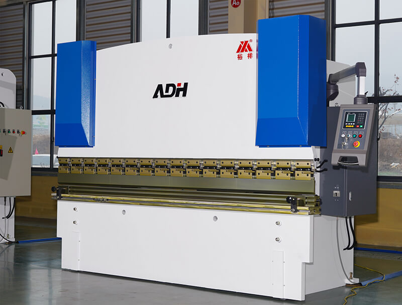
NC press brake machines are early conventional bending machines. NC press brakes use the torsion bar to connect the Y-axis on both sides of the ram (left Y1 and right Y2) and to drive hydraulic cylinders on the uprights.
Then, the ram can move up and down synchronously to bend metal sheets. NC press brakes are very suitable for low-cost, easy-to-operate workpiece bending but not high-precision and high-volume production.
Since the NC press brake is mechanically synchronized, it cannot provide real-time feedback on the bending error and automatically adjust the error. This can lead to poor bending accuracy.
In addition, the NC press brake drives cylinders up and down through the torsion shaft, and the long-term load can lead to the deformation of the torsion shaft.
To better understand how NC and CNC systems differ in structure and precision, you can read NC vs CNC Press Brake: Key Differences.
2.6 What Is CNC Press Brake
CNC is the abbreviation for Computer Numerical Control. CNC press brakes are essentially mechanical tools that integrate a computer numerical control system with hydraulic press brakes.
Generally speaking, CNC press brakes are driven by a hydraulic or electrical system.
After being equipped with the computer numerical control system, the press brake is able to effectively and precisely bend metal materials into various desired profiles.
Hydraulic press brakes occupy the vast majority of bending equipment use share. These machines are typically used in metal forming and fabricating.
The hydraulic press brake is powered by the hydraulic system. Y1 and Y2 axis control oil cylinders directly drive the ram to do the synchronous movement.
Hydraulic press brakes have a long history of utilization and mature technology development.
During the bending operation, hydraulic press brakes are stable and reliable and are very suitable for large-volume, heavy-tonnage workpiece processing.
The purely electric CNC press brake is driven by an electric motor and does not use hydraulic devices or oil cylinders, so there is no problem with oil leakage.
Also, the motor only starts when bending is required and automatically shuts off when not in use. This reduces energy consumption and bending costs.
Electric press brakes can provide accurate and fast bending operations. However, an electric press brake is more suitable for dealing with smaller tonnages (Tonnage refers to the bending force of the particular press brake).
CNC press brake can be divided into two types according to the movement of the upper tools (punch) and lower tools (die).
Down moving:
It includes a fixed worktable (bottom), which fixes the lower tools (dies) on the table.
The upper tools (punch) are subjected to a downward force, and the upper and lower dies act together on the sheet metal an plate to complete the bending process.

Up moving:
This type of press brake has the same parts as the first type of bending machine. However, in this type, the upper part is fixed and the bottom part is the moving counterpart.
The bending preparation time of the CNC press brake is very fast because there is a CNC system that accurately calculates the position of the ram and back gauge.
The CNC press brake can also check for errors during the bending process, switch between different bending modes, and position desired to bend angles and bending lengths.
Additionally, the CNC system is able to calculate the correct bending sequence, repeating the bending action several times until the piece of sheet metal is produced into profiles.
Overall, the CNC press brake is programmable for the entire bending process and is able to provide high-precision, customized bending.
Ⅲ. Physical Mechanisms: The Underlying Logic of Metal Bending
If the press brake’s mechanical structure is its “body,” then the physical mechanism is its “soul.” When the foot pedal is pressed, what occurs is not a simple mechanical motion but a complex interplay of contact mechanics, crystal lattice rearrangement, and energy transformation. To become a true bending expert, one must see through this invisible layer of physical logic.
3.1 In-Depth Analysis of the Three Bending Methods
At first glance, bending may appear to be a single downward stroke of the ram. Yet, at the micro-physical level, the interaction between the ram and die defines three distinct process logics. Understanding these boundaries is the first step toward precision forming.
1. Air Bending: The Art of “Suspended” Equilibrium
This method currently dominates over 90% of industrial applications.
- Physical Principle: Air bending follows a three-point bending model—the sheet contacts only the punch tip and the two shoulders of the V-die, leaving the bottom of the sheet “floating.”
- Core Logic: The bend angle is determined by depth (Y-axis position) rather than die geometry.
- Practical Advantages:
- Exceptional Flexibility: By adjusting ram depth, a single set of 88° or 86° tooling can produce angles ranging from 90° to 175°. This principle forms the foundation of CNC press brake technology. You can learn more about its precision from our brochures.
- Achilles’ Heel: Because the sheet doesn’t fully conform to the die, forming accuracy relies entirely on material consistency. Even a 0.1 mm variation in thickness or a slight difference in tensile strength can alter the springback, causing angular deviation. This is precisely why modern high-end machines must be equipped with a Laser Angle Measurement System (LAMS) for real-time feedback.
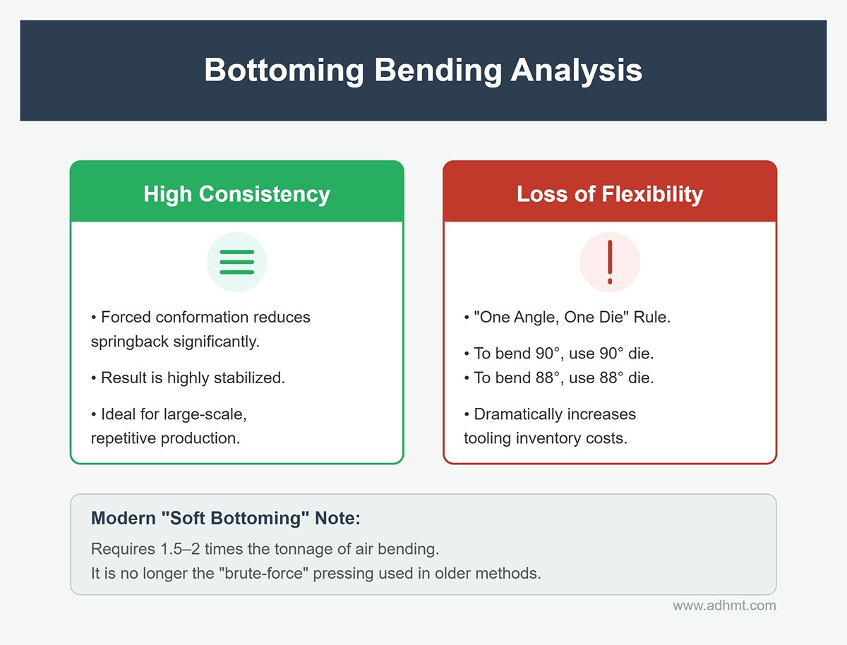
2. Bottoming: Geometric Lock-In
- Physical Principle: The contact changes from three points to three points plus surface contact. When the ram descends to the bottom of the V-die, the sheet is forced to conform to the die walls, eliminating uncertainty caused by material suspension.
- Core Logic: The angle is defined by the geometry of the die.
- Practical Value:
- High Consistency: Because of forced conformation, springback is greatly reduced and stabilized, making this method ideal for large-scale, repetitive production.
- Loss of Flexibility: To bend 90°, you must use a 90° die; to bend 88°, you need an 88° die. This “one angle, one die” rule dramatically increases tooling inventory costs.
- Note: In modern precision manufacturing, “bottoming” usually refers to soft bottoming, where the required tonnage is roughly 1.5–2 times that of air bending—rather than the brute-force pressing used in older methods.
3. Coining: Violent Reshaping
- Physical Principle: This process involves cold flow at the microscopic level. Using forces 10 to 30 times higher than those in air bending, the metal lattice is fractured and rearranged, visibly thinning the compressed area of the sheet.
- Core Logic: By disrupting the internal stress structure of the material, coining achieves zero springback.
- Practical Value:
- Extreme Precision: The formed angle is exactly what you set—virtually unaffected by material properties.
- High Cost: This technique severely shortens the lifespan of both the press frame and the dies. Today, it is reserved for ultra-precise, small-part applications and has largely disappeared from general sheet metal fabrication.
3.2 Material Science and Forming Mechanics
A press brake operator is, in many ways, also a materials scientist. Invisible material properties constantly influence the final quality of the workpiece.
1. Neutral Axis and K-Factor
When a metal bends, the inner side is compressed (shortened) while the outer side is stretched (lengthened). Between these two lies a layer that neither elongates nor contracts—the neutral axis. Fundamentally, all flat pattern calculations aim to determine the length of this axis.
- K-Factor: A coefficient defining the location of the neutral axis (K = t/T), representing the ratio of the neutral axis distance from the inner surface to the total sheet thickness.
- Hardness Rule: The harder the material, the more resistant the neutral axis is to shifting.
- Soft Aluminum: K ≈ 0.5 (the neutral axis lies near the center).
- Stainless Steel: K ≈ 0.40 (the neutral axis is forced inward).
- Expert Tip: If you calculate stainless steel using mild steel parameters, your finished part will always be too long, because you’ve misjudged the neutral axis position.
2. Springback: The Elastic Revenge
When the ram pressure is released, residual elastic stress within the material attempts to restore its original shape, resulting in a larger bend angle.
- Counterintuitive Truth: Large-radius (large R) bends exhibit more springback than sharp bends!
- This happens because sharp bends force most of the material into the plastic deformation zone (permanent deformation), while large-radius bends leave more material in the elastic deformation zone, which rebounds like a spring once unloaded.
- Grain Direction Effect:
- Perpendicular to Grain: Higher strength but greater springback (crosses more grain boundaries).
- Parallel to Grain: Less springback but higher risk of cracking (tears along grain boundaries).
3. Tonnage Calculation: Exponential Fear
When choosing equipment and process parameters, always respect the laws of physics. The bending force (tonnage) required follows a harsh square-law relationship with sheet thickness:
This means:
- Thickness Trap: If sheet thickness (S) doubles—from 2 mm to 4 mm—the required tonnage doesn’t double; it quadruples!
- V-Die Leverage: Halving the lower die opening (V) doubles the required tonnage.
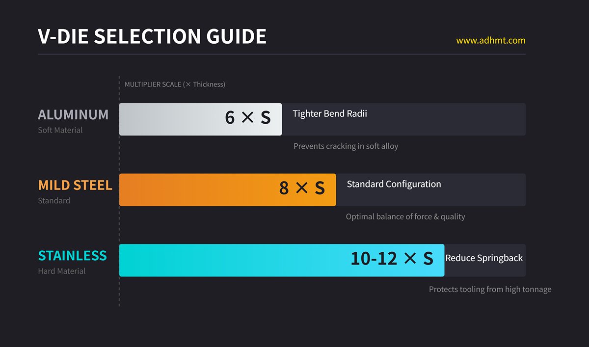
Rule of Thumb — V-Die Selection: To balance bending force and part quality, the width of the V opening should be chosen according to the material type:
- Mild Steel: (V = 8 × S) (standard configuration)
- Stainless Steel: (V = 10–12 × S) (to reduce springback and protect costly dies, a wider V is recommended)
- Aluminum: (V = 6 × S) (since aluminum is soft, a smaller V can be used for tighter bend radii without cracking)
Once you grasp these fundamental principles, you gain the ability to see beyond surface phenomena—every parameter adjustment becomes a precise, physics-based calculation rather than blind trial and error.
Ⅳ. Engineering Practice: Die Science and Parameter Configuration
If physics is the “soul” of a press brake, then tooling and parameter setup are its “hands.” In practice, many million-dollar machines end up as “expensive scrap” not because of poor mechanical accuracy, but due to neglect of the tooling system and misinterpretation of process parameters. This chapter tackles the ultimate challenge—“how to bend precisely”—through three engineering dimensions: tooling selection, deformation compensation, and digital programming.
4.1 Tooling System: The Source of Precision
In modern precision manufacturing, tooling is no longer just a consumable—it defines the upper performance limit of the equipment. A well-engineered tooling system can compensate for machine rigidity shortcomings; conversely, poor-quality tooling can ruin even the most advanced control system.
1. Interface Standards: The Choice of Schools
The interface standard of press brake tooling determines both changeover efficiency and machining accuracy. There are three major design philosophies:
- European Standard (Promecam/Amada Style): Currently the most widely adopted global standard. It features a narrow tang (13 mm) with an offset design. Advantages include excellent cost performance and a vast supplier network; disadvantages lie in its reliance on manual clamping plates, which can compromise vertical alignment and result in slower tool changeovers.
- New Standard (Wila/Trumpf New Standard): Often dubbed the “Ferrari” of tooling systems. It employs a self-centering, self-locking hydraulic or mechanical clamping mechanism (Safety Click). With a single press, the punch automatically seats and aligns itself with precision within ±0.01 mm. This is the definitive choice for automated bending cells and high-frequency tool change operations. Though expensive, the dramatic reduction in downtime (and corresponding productivity gains) easily justify the investment.
- American Standard: Characterized by its simple flat tang design. Because it requires cumbersome manual alignment and is prone to cumulative errors, it’s gradually disappearing from modern precision sheet‑metal work, remaining mostly in older, heavy-duty machines.
2. Upper Tool Selection: The Art of Clearance
A novice operator focuses on whether the punch can press down; an experienced engineer focuses on whether it will collide.
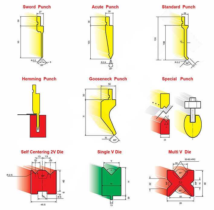
- Gooseneck Punch: An essential tool for forming deep boxes. When bending the final flange of a U‑shaped part, a straight punch often interferes with the pre‑bent sides. The gooseneck’s recessed neck design creates clearance for return flanges. Expert tip: Balance throat depth against strength. An overly deep neck may flex elastically under high tonnage, reducing angle accuracy.
3. Lower Die (V Die) Selection: Beyond the “8× Rule”
Textbooks often cite the formula for V‑opening width as V = 8×S (where S is sheet thickness). In practice, rigidly following this rule can be risky.
Stainless Steel Exception: Because stainless steel has high yield strength and significant springback, use
A wider V‑opening not only reduces bending force—protecting the press frame and tooling—but also increases the bend radius (R‑corner), effectively preventing outer‑surface cracking.
Aluminum Pitfall: Aluminum is very soft and prone to drag marks along the V‑shoulders. Choose
V = 6 ×S
to minimize sliding distance, or use a urethane pad or roller V‑die to convert sliding friction into rolling contact, achieving a flawless finish.
4.2 Deflection Compensation (Crowning): Countering Physical Deformation
When the hydraulic cylinders at both ends of the ram apply tons of pressure, the ram inevitably bows upward like a yoke, while the lower bed sags downward. This phenomenon is known as the “Canoe Effect.”
Without correction, this deformation causes a typical defect: a larger angle (under‑bent) in the middle and smaller angles (over‑bent) at both ends. To counteract this inherent behavior, a crowning system is required.
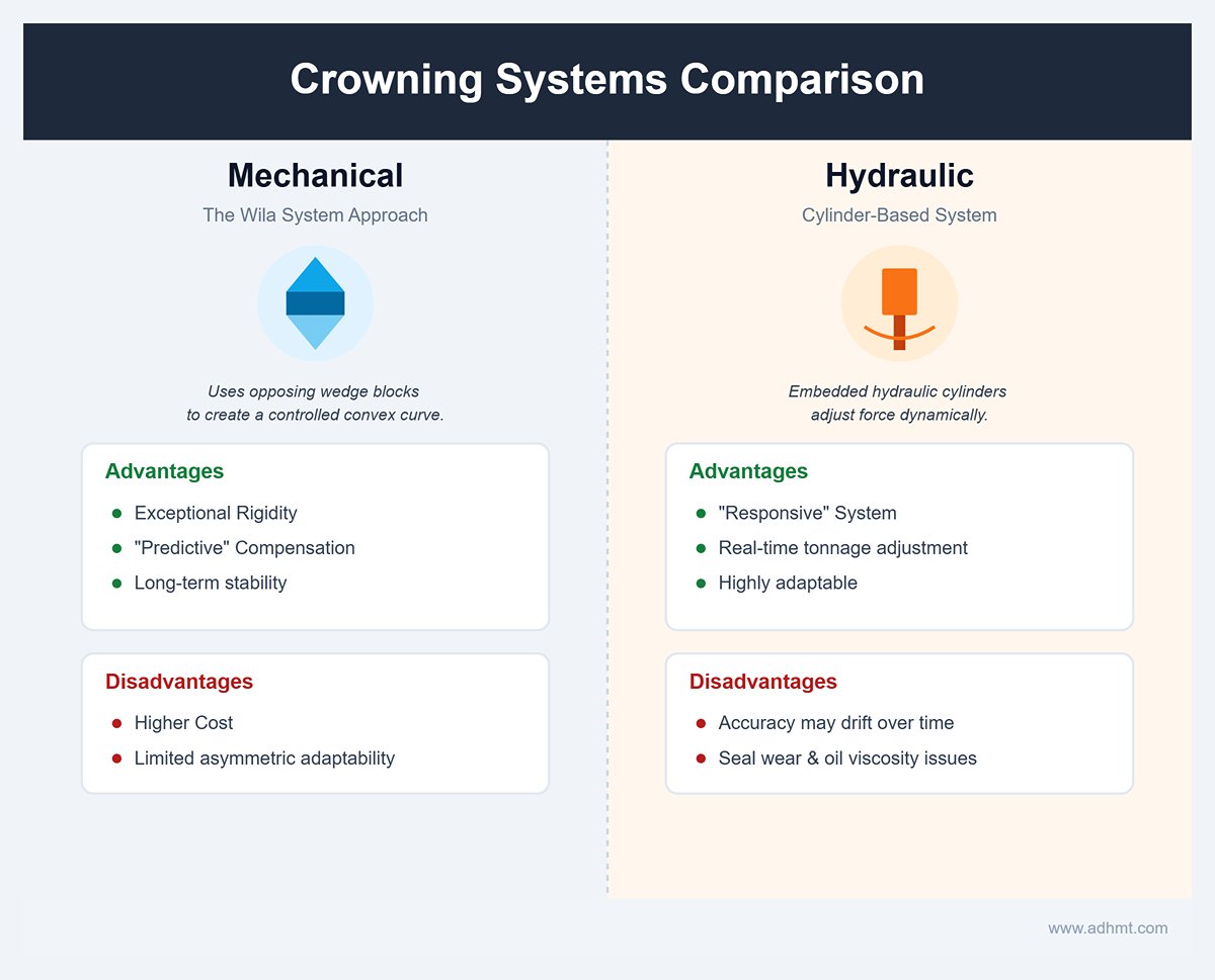
1. Mechanical vs. Hydraulic Crowning
- Mechanical Crowning: Represented by the Wila system, it uses two sets of wedge blocks beneath the table that move against each other, creating a controlled convex curve along the bed’s centerline.
- Advantages: Exceptional rigidity and “predictive” compensation. Once set, it maintains long‑term stability—ideal for high‑precision work.
- Disadvantages: Higher cost and limited adaptability to asymmetric loads.
- Hydraulic Crowning: Utilizes a series of hydraulic cylinders embedded beneath the bed.
- Advantages: A “responsive” system that dynamically adjusts lifting force based on real‑time tonnage—highly adaptable.
- Disadvantages: Accuracy may drift over time due to seal wear or temperature‑induced oil viscosity changes.
2. Practical Diagnosis and Calibration Mnemonics
How can you verify whether your compensation setting is correct? Perform the “three‑point test”: bend a test strip as long as the machine to 90°, then measure the left, center, and right angles.
- Center > Ends (e.g., 92°, 90°, 90°): The center isn’t pressed enough—insufficient compensation. Increase the crowning value.
- Center < Ends (e.g., 88°, 90°, 90°): The center is over‑pressed—excessive compensation. Reduce the crowning value.
- Note: If you see 90° on the left and 92° on the right, that’s a ram‑leveling issue (Y1/Y2 balance), not a crowning problem—don’t adjust the compensation.
4.3 CNC Programming and Digital Workflow
In the era of Industry 4.0, a press brake is no longer an isolated machine—it’s a data terminal within a smart factory ecosystem.
1. The Game‑Changer: Offline Programming
Traditional “on‑machine programming” is a productivity killer—every minute an operator spends entering parameters means costly idle time for an expensive machine. Offline software (such as Delem Profile S, Metalix, or RobotStudio) moves this task to the office. While engineers simulate bends on a computer, machines on the shop floor keep running at full speed. More importantly, it enables full virtual collision detection—will the workpiece hit the backgauge during rotation? Can the punch reach deep cavities? Discovering these issues digitally costs nothing; discovering them on the machine can mean scrapped parts—or worse, a crash.
2. The Evolution of Data Flow: From DXF to STEP
DXF (2D): The industry’s current bottleneck. A DXF file is merely a collection of lines, forcing the system to guess which are outlines and which are bend lines—an error‑prone process (e.g., mistaking a centerline for a bend line) that also omits critical data such as thickness and material properties.
STEP (3D): The format of the future. A 3D model carries all metadata—material type, bend radius, grain direction, and more. Advanced CNC systems can directly import STEP models to auto‑unfold parts, match tools, and generate programs. This marks the shift from “drawing‑driven” to “model‑driven” manufacturing—an essential milestone on the road to true Smart Manufacturing.
Ⅴ. What Are the Common Types of Press Brakes?
According to the different force application methods, press brakes can be primarily divided into mechanical press drive, hydraulic press drive, and pneumatic and servo press drive.
Although different types of press brake vary in characteristics, the main difference consists in the power source.
5.1 Mechanical Press Brake
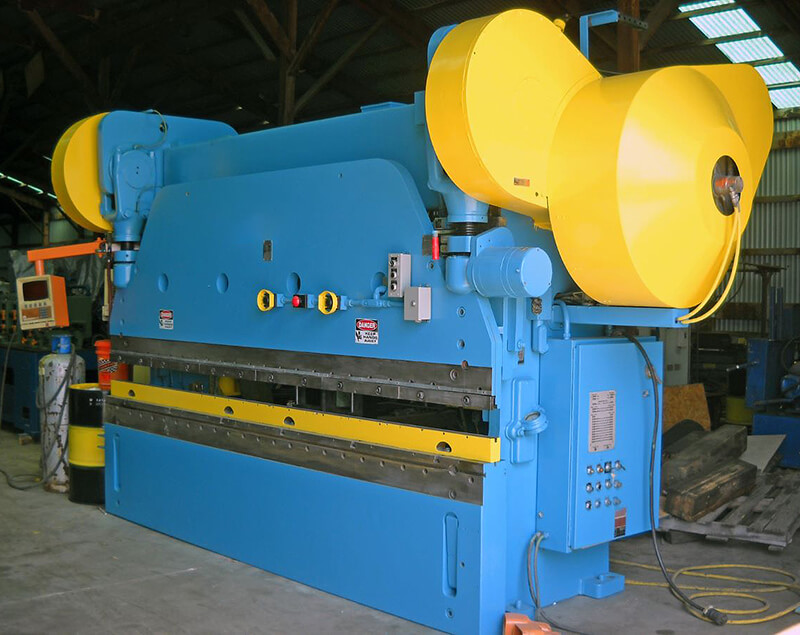
The main parts of mechanical press brakes include a workbench, ram, electric motor, flywheel, clutch, and brakes. The flywheel is driven by an electric motor.
Through the clutch, it is connected to the gear shaft to maintain the ram's motion. The brakes stop the movement of the gear shaft as soon as the drive shaft is disconnected from the flywheel.
Advantages
It is known for its high-speed operation and consistent performance, making it well-suited for repetitive tasks, and low-cost in the early stage owing to relatively simple and outdated technology. It has a small wear cost and low maintenance cost.
It has high bending and load-bearing capacity, which can exceed the rated tonnage 2-3 times. It is also friendly for beginners because it is easy to operate and has an intuitive control system.
Disadvantages
It can neither adjust the stroke during bending nor reverse it at any time, which is poor flexibility.
It can not perform more intricate bending work, and its functions are limited. Also, it has higher safety risks and is not as fast as a hydraulic press brake when changing tools and adjusting.
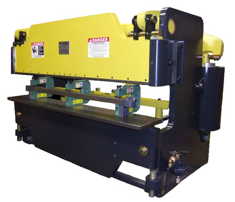
5.2 Hydraulic Press Brake
The machine tool drives the ram movement with two synchronized hydraulic cylinders on the C-frames, allowing for greater control over the bending process.
The light curtain safety device of the hydraulic press brake allows the ram to be stopped at any time, reverse the operation stroke, and control the speed. Hydraulic press brakes have become a staple in the metalworking industry due to their versatility and power.
Advantages
Adopting a CNC system, hydraulic press brakes offer exceptional bending accuracy and can intelligently handle the bending of different materials, different tonnages and bending lengths, thicknesses, angles, etc.
It has high intensity and nice rigidity, smooth and reliable operation, high precision, and versatility. It can handle a wide range of materials and thicknesses, including plate metal sheets. It has overloading protection to avoid damaging the die and machines.
Hydraulic press brakes are divided into torsion shaft press brakes, mechanical hydraulic press brakes, and electro-hydraulic press brakes.
Disadvantages
Complexity and maintenance, noise pollution, potential for oil leaks and spills, slower approach and return speeds compared to electric press brakes, high initial cost, and significant floor space requirements, especially for larger models. Operating a press brake requires skilled operators to maximize efficiency.
5.3 Pneumatic Press Brake
The power source of the pneumatic press brake is mainly compressed air or gas. The air pressure generated by the gas is used to apply press brake tonnage to the ram for bending.
The machine delivers compressed air to the cylinder or pipe connected to the pressure mechanism. When filled with gas, the pressure drives the tooling downward.
After the movement is complete, the gas is discharged through the exhaust valve, and the brakes return to their initial position.
Advantages
It has low requirements for operation and training. It is fast to set and adjust the time, simple to maintain and has fewer pneumatic components, which can save maintenance costs.
Disadvantages
Due to low pressure, it is hard to bend thick materials. Compared to hydraulic press brakes, it makes more noise. Its bending ability and bending force are lower than those of hydraulic press brakes.
5.4 Servo Press Brake
The power of the servo press brake mainly comes from two synchronous servo motors, which provide energy through belts and pulleys. The servo press brake is usually suitable for bending a small number of customized workpieces.
Advantages
The servo press brake is very flexible. The servo motors accurately control the stroke and speed of the ram. The operating sound of the servo press brake is very low, and it will not produce noise during operation.
When the bending starts, the servo motors start running; when it stops, the servo motors will also stop. This may save power and reduce production costs.
Moreover, the servo press brake is not equipped with oil cylinders, so the problems of oil leakage and cleaning do not need to be considered.
Disadvantages
It has high requirements for the operating environment. Highly dependent on the stability and operability of CNC systems.
It is hard to maintain and repair the servo press brake. Once trouble occurs, it requires high techniques and a long time. The upfront cost of servo-electric press brakes is higher than other models, which may deter smaller-scale operations.
| Type | Key Features | Best For |
| Mechanical | High speed, consistent operation | High-volume, simple bending tasks |
| Hydraulic | Adjustable stroke, high accuracy | Heavy-duty applications, thick materials |
| Pneumatic | Quick setup, lightweight design | Light to medium-duty manufacturing |
| Servo-Electric | Precision, energy efficiency, repeatability | Complex, high-precision industrial processes |
Ⅵ. How Does a Press Brake Work?
6.1 How a Press Brake Works: Step-by-Step
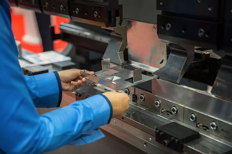
- Material placement: place the thin metal sheet on the press brake bed against the back gauge fingers for proper alignment.
- Clamping: the workpiece is fixed firmly between the upper punch and bottom die. Proper clamping force is vital for avoiding slipping during bending.
- Bending: the ram (bearing the upper punch)descends and exerts pressure on the workpiece, pressing it into the V-shaped holes of the bottom die. This deforms the metal into the required bending angle.
- Retract: after achieving the programmable bending angle, the ram retracts and releases the workpiece pressure.
- Release and remove: release the clamping device, and the operator will move the workpiece from the press brake bed.
6.2 Comparison
| Power source | Describe |
| Mechanical | By synchronously driving the slider movement through the oil cylinders on the two side pillars, the stroke and tonnage can be stopped and adjusted during the bending process. |
| Hydraulic | By synchronously driving the slider movement through the oil cylinders on the two side pillars, the stroke and tonnage can be stopped and adjusted during the bending process |
| Pneumatic | Using compressed air to drive slider movement |
| Servo motor | Precise control of slider movement using servo motors |
Note:
- The bigger the tonnage, the thicker the bending material thickness.
- Once the mechanical press brake stroke is started, it must be completed. It can be paused but not reversed.
- The hydraulic press brake can be stopped and adjusted the stroke and tonnage during bending.
Ⅶ. Key Components of a Press Brake
7.1 Punch and Die
What Is Press Brake Punch and Die?
Press brake dies are crucial for bending sheet metal. They consist of the upper die (punch) and the bottom die (die). Only matched punches and dies working together on the metal plate can produce the final profile.
During bending, extrusion and friction occur between the dies and the sheet metal, leading to die wear over time. The huge pressure generated when the dies bend the metal plate can cause the temperature of the contact surface to rise, damaging the dies.
Press brake tooling is not suitable for dealing with metal plates with high hardness and thickness, especially cylindrical workpieces.
The press brake's back gauge is located behind the machine and is used to position the workpiece. The more shafts there are for the back gauge, the higher the workpiece's bending accuracy.
The press brake controller can control the movement of multiple components, including toolings, back gauges, etc. The light curtain system of the press brake can protect the operator from being injured by the machine.
How to Select Press Brake Punches and Dies
When selecting press brake dies, the die material's hardness, heat resistance, and wear resistance must be considered. The hardness, thickness, length, and ductility of metal plates should also be considered. Appropriate materials for the plate being bent should be selected for the dies.
Generally, the bottom die is used according to the standard of 5 ~ 6T, and the length is longer than the metal plate. When the material is harder, and the thickness is larger, the dies with wider grooves shall be used.
When selecting the punches, the angle of the workpiece should be determined according to the shape of the product so as to select the appropriate punches. There are many kinds of materials for press brake punches and dies. Steel is currently the preferred material for making press brake dies.
For example, carbon tool steel, low alloy tool steel, high carbon high chromium or medium chromium tool steel, medium carbon alloy steel, high-speed steel, matrix steel, cemented carbide, steel bonded cemented carbide, etc.
These high-quality steels are made by special heat treatment. They are highly hard, not easy to wear, and have a strong load capacity. However, they must not exceed the limited pressure that the dies can bear during bending.
Types of Press Brake Punches and Dies
90-degree dies, acute angle dies, beading dies, box-forming dies, channel-forming dies, corrugating dies, curling dies, four-way die blocks, gooseneck dies, hemming dies, multiple-bend dies, radius dies, rocker-type dies, rotary bending dies, seaming dies, tube, and pipe forming dies, u-bend dies, and V-dies. Available in various shapes and sizes, punches are adaptable to different bending requirements.
7.2 Frame
The frame is the main structure of the press brake, providing support and rigidity to withstand the high forces during bending. Typically made from welded steel plates, it ensures stability and prevents deformation under stress.
7.3 Bed
The bed is the flat surface where the metal sheet is placed during bending. It usually has a V-shaped groove to help align and position the sheet accurately, serving as the base for the die.
7.4 Ram
The ram is the moving part of the press brake that holds the punch and applies force to the metal sheet. It moves vertically, driven by a hydraulic or mechanical system, to press the punch onto the material and create a bend.
7.5 Backgauge
The backgauge is an adjustable stop that positions the metal sheet accurately before bending, ensuring precise and consistent placement for uniform bends.
7.6 Hydraulic or Mechanical System
In hydraulic press brakes, the ram is powered by hydraulic cylinders, offering precision and handling heavier workloads. Mechanical press brakes use a flywheel and crank mechanism, providing simplicity and cost-effectiveness for some applications.
7.7 Control and CNC System
Modern press brakes often have CNC (Computer Numerical Control) systems that automate and control the bending VI. What Are Press Brakes Used for?
A press brake is mainly used for bending and forming metal plates. In the past, workers could only bend metal plates by pounding them manually.
With the continuous development of science and technology, mechanical press brakes, hydraulic press brakes, and electric press brakes have entered the market one after another.
Currently, press brakes are widely used in various fields of processing and production to improve production efficiency.
Press brakes are mainly used for metal processing and manufacturing in the aerospace, automobile, marine industry, agriculture, energy, military, transportation, and other fields.
In the automotive industry, these bending machines can produce body panels, frames, and brackets. In the aerospace field, they can produce aircraft components and fuselage structures. They can also produce moulded metal shells and covers for electronic equipment. Press brakes make frames and duct parts for the architecture and construction industries.
Ⅷ. Conclusion
This passage discusses the press brake's concept, working principle, and importance. I hope you can have a more comprehensive understanding of the press brake and recognize its vital role in modern industrial manufacturing.
When exploring the press brake world, it is pivotal for you to choose a mature and advanced supplier. My company, ADH Machine Tool, is such a reliable partner.
We specialize in offering top press brakes, shearing machines, and laser-cutting machines. Our products are well-designed and perform well to meet your various sheet metal processing needs.
I cordially invite you to visit my company's product page to learn more about our product press brake range and technical advantages. You can also explore our high-precision CNC Press Brake and heavy-duty Large Press Brake for diverse industrial needs. For more detailed specifications, please refer to our downloadable brochures, or feel free to contact us for customized solutions.
Whether for effective solutions for improving production efficiency or improving product quality via advanced technology, we all offer you professional support.
Ⅸ. FAQs
1. What are the advantages of using a press brake?
Using press brakes in precision sheet metal fabrication offers several advantages, including increasing production efficiency, achieving high precision, and reducing material waste. Modern press brakes are equipped with advanced CNC systems, allowing for quick setup and switching between different bending operations, thereby minimizing downtime and enhancing output.
Additionally, metal bending machines can handle various materials and perform complex bending operations, which is particularly important in industries such as aerospace, automotive, and electronics.
2. What is the primary function of a press brake?
A press brake is designed to bend and form sheet metal into various shapes and sizes. It is widely used in industries like manufacturing and metal fabrication, offering precision in shaping metal components.
3. How does a press brake differ from other types of presses?
Press brakes utilize specific tools, including a punch and die, to shape metal with accuracy. They differ from other presses by their focus on precision bending, often employing hydraulic or mechanical force to accomplish this.
4. What materials are typically processed using a press brake?
Common materials include steel, aluminum, copper, and other malleable metals. The choice of material often depends on the application and required properties of the finished product.
5. What factors influence the cost of a press brake machine?
Several variables affect the cost, including the machine's size, type (such as CNC or hydraulic), capacity, and additional features. Maintenance needs and technology advancements also play a significant role in pricing.