I. Introduction to Press Brake Bending
Press brake bending is a common metal fabrication technology that bends metal into specific shapes. It is vital in metal fabrication industries and manufacturing. It involves a machine known as a press brake. If you want a structured overview of how different methods work in practice, you can refer to this detailed Guide to Press Brake Bending Methods.
Types of press brake machines include manual press brakes, hydraulic press brakes, CNC press brakes, servo-electric press brakes, and mechanical press brakes. Each type has its own advantages and characteristics during press brake operation.
In the process of bending, the piece of sheet metal is placed on the press brake and can be bent into the required angles and shapes by exerting pressure.
In the bending process, the workpiece is clamped between the top punch and bottom die and can be bent by exerting pressure. The whole bending process is programmed and smooth. Knowing the press brake bending basics is vital to designing and producing sustainable, intelligent products.
II. Bending Process Overview
1. Steps in Press Brake Bending Machines
(1) Material Loading, Alignment, and Securing
The first step in the bending process is loading the metal sheet onto the press brake machine. The material is typically placed on the machine's bed, ensuring it is aligned with the tool centerline. Proper alignment is critical to avoid any skewing during the sheet metal bending process, which could lead to inaccuracies in the final product.
Once aligned, the sheet metal is secured in place using clamps or a backgauge system. These systems ensure that the material stays in position throughout the bending operation, preventing any movement that might affect the bending accuracy.
(2) Setting Up the Press Brake
After the material is secured, the press brake machine needs to be properly set up. This involves selecting the appropriate punch and die tooling based on the material type, thickness, and the desired bend radius. The machine operator also needs to adjust the bending angle, the stroke length, and the force applied by the press brake. For more insights into tooling setup and efficiency, refer to the Guide to Press Brake Tooling and Bending.
These parameters are crucial in achieving the desired bend with the right amount of precision. Additionally, the machine's control system may need to be calibrated for specific part dimensions, ensuring that the bend is produced within the specified tolerances. For a deeper understanding of automated setup and optimization, you can review ADH’s CNC Press Brake solutions for modern metal fabrication.
(3) Bending Operation
Once the setup is complete, the bending operation can begin. The press brake applies force through the punch, pressing the sheet metal into the die to form the desired bend. The amount of force applied is carefully controlled to avoid material cracking or improper bending.
Throughout the operation, the operator monitors the process to ensure that the bend depth and angle are achieved accurately. If the machine is CNC-equipped, the bending parameters can be pre-programmed, allowing the machine to automatically adjust for optimal results.
(4) Post-Bending Inspection and Adjustments
After the bend is complete, the operator will inspect the part to verify that the bend meets the required specifications. Any adjustments to the machine or tooling can be made if necessary.
Depending on the complexity of the part, additional processes, such as finishing or trimming, may also be performed to refine the shape and ensure the part fits precisely into the final assembly. You can find additional reference data and technical insights in ADH’s downloadable brochures.
2. Types of Press Brake Bending Techniques and Applications
There are different types of bending techniques for every press brake:
(1) Air Bending
Process
Air bending is one of the commonly used technologies in metal bending, which will not make metal contact the die directly. The punch will press the metal sheets into the die to some depth without connecting the bottom.
The reason for bending is the metal sheet lies on the top of the v die at the bottom and utilizes the bottom air gap. The bending angle is determined by the depth at which the punch descends into the die. Additionally, air bending requires less power compared to other techniques, and that can extend the life of machinery.
Advantages
Air bending stands out for its versatility. Because the metals do not utterly fit the shape of the die, thus using the same set of tools is able to achieve a bending angle, which decreases the tool changing time and improves the efficiency. Compared with other methods, air bending needs less force, thus can prolong the machine’s lifespan.
Considerations
- Springback: The material springs back slightly after bending, so you need to bend it slightly more to get the right angle.
- Angle Accuracy: Achieving precise angles may require additional adjustments due to springback.
Applications
Air bending is widely applied in the hydraulic press brake for flexibility, especially when multiple bending die angles are needed in the same work. It can be used to bend multiple metal materials and produce small-medium scale products.
Many industries have benefited from this technology, such as automotive, aerospace, and construction. There is no need for these industries to replace the tool constantly, and can generate various components.
(2) Bottom Bending
Process
In bottom bending, the metal sheets are utterly pressed in the bottom of the v-shaped dies. The punch forces the metal to form the same shape as the die. Unlike air bending, bottom bending forces metal to the whole contact with the top of the punch and two sides of the tooling.
However, compared with coining, the exerting pressure is relatively more minor. Thus, the bending angle is hard to match the die utterly.
Rebound
The apparent phenomenon in bottom bending is “rebound”. When the metal sheets have been bent and released, they will shrink slightly to recover to their original shape. This elastic recovery may cause problems when the precision is paramount.
To offset rebound, the punch will bend the material excessively. Or the die with a finer angle can be pre-adopted to bend to ensure the final bending angle is accurate in case rebounding occurs. This method is applicable to bend parts with relatively simple geometry.
Advantages
- High Precision: Provides greater control over the bend angle, reducing the need for adjustments.
- Reduced Springback: Minimizes springback, ensuring consistent results.
Considerations
- Higher Force Requirements: Needs more tonnage than air bending, increasing wear on the machine and tooling.
- Tooling Wear: The increased force can lead to faster wear of the punch and bottom of the die.
Application
Under the circumstance of emphasizing consistency and precision, bottom bending is preferred. It is widely applied to the industry requiring minimum difference and uniform components, such as electronics.
(3) Coining
Process
Coining is a technology that uses strong power to press the metal sheet and forces it to deform, bend, and thin to precisely fit the die shape. This process is renowned for its enormous power and will make people reminiscent of the coin’s coining process.
It requires a higher-strength press brake and a more intricate tooling design and is mainly used for components requiring high-precision production.
Advantages
- Extreme Accuracy: Produces highly accurate bends with virtually no springback.
- Consistency: Ensures consistent bend angles across multiple parts.
Considerations
- High Tonnage: Requires substantial force, which can place considerable demand on both the press brake and the tooling.
- Tooling Stress: The intense pressure can lead to rapid wear and potential damage to the tooling.
Relation to coin production
“Coining” refers to the method of coin production initially. In the process of coin production, the blank metal plates will be pressed between the two dies under tremendous pressure, thus ensuring the metal flowing and die filling. A coin with a complex design will be produced. Similarly, the metal will be pressed in coining technology to capture each mini detail of the die.
Key Comparison Table: Pressure, Accuracy, Tool Wear, and Suitable Applications
| Key Metric | Air Bending | Bottom Bending | Coining |
|---|---|---|---|
| Required Pressure (Tonnage) | Low | Moderate | Very High |
| Bending Accuracy | Moderate (depends on machine precision and springback compensation) | High (springback effectively controlled) | Extremely High (virtually no springback) |
| Tool/Machine Wear | Low | Moderate | High |
| Flexibility & Application | Extremely versatile—one die can produce multiple angles; ideal for small-batch or varied production | Excellent repeatability; suited for medium to large batches with strict angle requirements | Best for high-volume production requiring ultimate precision, though rarely used today due to cost and wear |
III. Factors Influencing Press Brake Bending
1. Material Properties
The properties of the material being bent play a crucial role in the press brake bending process. Different materials respond differently to bending forces due to variations in their physical and mechanical properties. Understanding these properties is essential for selecting the appropriate bending parameters and ensuring optimal results.
Material Thickness
Thickness of the material is one of the most critical factors in press brake bending. Thicker materials require more force to bend, which can impact tooling selection and machine settings. The bending force must be sufficient to achieve the desired angle without causing damage, such as cracking or excessive deformation.
Additionally, thicker materials tend to exhibit less springback, making it easier to achieve accurate bends. Operators must consider the thickness in their calculations to ensure the press brake is capable of handling the required force efficiently.
Material Hardness
The hardness of the material also affects the bending process. Harder materials, such as high-strength steels, require more force to bend and are more prone to cracking if not handled correctly. Softer materials, such as aluminum, require less force but can be more susceptible to surface marking and denting.
The material's hardness influences the choice of punch and die, as well as the bending method (air bending, bottoming, or coining). Properly matching the tooling to the material's hardness helps in achieving consistent results without compromising the material's integrity.
Material Type
Different materials, including steel, aluminum, copper, and their alloys, have unique properties that affect their behavior during bending. For example:
- Steel: Known for its strength and durability, steel is commonly used in press brake bending. It typically requires higher bending forces and careful handling to avoid issues like cracking or excessive springback.
- Aluminum: This material is easier to bend than steel but is more prone to surface deformation. It has a higher springback tendency, requiring adjustments in bending angles to compensate.
- Copper: Copper and its alloys are ductile and formable, making them suitable for complex bends. However, they can be prone to surface damage, requiring softer tooling materials or protective coatings.
2. Tooling Considerations
Tooling is another critical factor in press brake bending, as the choice of punch and die directly impacts the quality and precision of the bends. Proper tooling selection and maintenance are essential for achieving consistent and accurate results.
Selecting the Correct Punch and Die
The selection of punch and die sets is paramount to the success of the bending operation. Factors to consider include:
- Punch Angle and Radius: The punch angle and radius must match the desired bend angle and radius. For sharper bends, a lower punch angle is required, whereas larger radii may necessitate different tooling. The punch radius also affects the internal bend radius, which can influence material flow and the final bend quality.
- Die Opening Width: The width of the die opening (V-width) should correspond to the material thickness and desired bend radius. A wider V-width allows for easier bending of thicker materials, while a narrower V die width is suitable for thinner sheets. The die opening must be carefully selected to avoid material damage and ensure accurate bends.
- Material Type of Tooling: The material of the tooling itself is important. For instance, harder tool materials like carbide are suitable for high-strength metals, while softer tool materials like aluminum or brass tools with protective coatings are ideal for avoiding surface damage on softer metals like copper or aluminum.
Tool Wear and Maintenance
Regular maintenance and inspection of press brake tooling are vital for maintaining precision and extending tool life. Tool wear can lead to inaccuracies and defects in the bending process. Key maintenance practices include:
- Regular Inspection: Tools should be inspected for signs of wear, such as cracks, chips, or deformations. Damaged tools must be repaired or replaced immediately to prevent compromises in bend quality.
- Tool Cleaning: Keeping tools clean from debris and buildup ensures smooth operation and prolongs tool life. Contaminants can cause uneven force distribution, leading to inaccuracies.
- Proper Storage: Tools should be stored in a manner that prevents damage and corrosion. Proper storage solutions, such as tool racks and protective covers, are essential for maintaining tool integrity.
Compatibility with Automation
With advances in CNC technology, press brake machines increasingly rely on automated systems for improved precision and efficiency. Tooling must be compatible with these systems to fully leverage the benefits of automation.
CNC-compatible tooling allows for quick and accurate tool changes, reducing setup times and improving production throughput. Additionally, advanced tooling systems may include sensors and feedback mechanisms to monitor and adjust bending parameters in real-time, ensuring consistent quality across production runs.
IV. Advanced Technologies in Press Brake Bending
Press brake bending is a widely used metal forming process involving the elastic deformation of the metal sheets under the pressure of press brakes' top punch and bottom die and plastic deformation.
1. CNC (Computer Numerical Control) Systems
The press brake adopts many advanced technologies, and CNC is the one. Through CNC technology, the press brake operation does not utterly rely on manuals. Instead, the preprogramming is advanced.
This means the construction and operators can design and input the specific parameters on the computer. The machine can be operated according to these instructions. The benefits of using CNC in press brake are as follows:
- Precision improved: the CNC technology can control the bending process precisely, thus achieving accurate and consistent bending.
- Repeatability: due to the machine being operated by pre-designed programs, each bending can achieve highly consistent results, regardless of the production quantity.
- Productivity improved: the automotive operation reduces the need for human manipulation. CNC machine tools can achieve intricate bending operations with high efficiency, decreasing production time and improving productivity.
- Flexibility: CNC technology allows the users to modify and adjust the bending parameters easily to adapt to the different task requirements.
- Setting time reduced: CNC machine tool can restore and recall bending programs without manual setting, reducing the transition time between the workpieces.
- Waste reduced: high precision and repeatability mean fewer errors and wastes, thus reducing materials and costs.
2. Laser Angle Measurement
Laser angle measurement systems provide real-time feedback on the bend angle, ensuring precise control and reducing the need for manual measurements and adjustments. This technology enhances accuracy and repeatability in bending operations.
Laser systems continuously monitor the bend angle, allowing for immediate adjustments. Precise measurements ensure that each bend meets the specified angle, reducing rework and scrap. Integrating laser measurement systems with CNC controls simplifies the bending process, making it easier for operators to achieve accurate results.
In the automotive industry, laser angle measurement systems help produce body panels with precise bends, ensuring that parts fit together correctly and meet design specifications. An automotive manufacturer reported a 15% reduction in rework and a 10% improvement in production speed after implementing laser angle measurement systems.
3. Advanced Backgauge Systems
Advanced backgauge systems enhance the positioning accuracy of the metal sheet, ensuring that each bend is made at the correct location. These systems can be CNC-controlled, providing automated and highly precise positioning.
Advanced backgauges offer accurate and repeatable positioning of the workpiece. CNC-controlled backgauge systems automate the setup process, reducing manual intervention. These systems can handle a wide range of sheet sizes and thicknesses, accommodating various bending tasks.

In large-scale manufacturing operations, advanced backgauge systems improve efficiency and accuracy, enabling the production of complex components with tight tolerances. A manufacturing plant reported a 20% increase in production capacity and a 15% reduction in scrap rates after integrating advanced backgauge systems.
These advanced technologies utterly transform the press brake bending process, making various industries more efficient and cost-effective.
Ⅴ. Core Principles Unveiled: The Science Behind Bending
1. Core Principles: The Science Behind Metal Bending
To truly master metal forming, one must understand how the material behaves under powerful external forces. This is not merely a mechanical action—it is a delicate interplay of materials science and mechanical engineering at the microscopic level. Grasping these foundational principles is the key to evolving from an operator who can simply “perform the task” into a technician who can “predict, diagnose, and optimize” the process.
(1) Elasticity and Plasticity: The Fundamental Logic of Metal Deformation
Imagine a metal sheet in your hands. When a press brake applies force, it undergoes two distinct stages of deformation—this dual behavior underlies all metal forming processes.
1)Elastic Deformation:
At the initial stage of loading, the metal behaves like a high-strength spring. It bends, but its internal crystal structure remains intact. If the force is released at this point, the material’s elasticity allows it to fully return to its original, flat form. This reversible change is not something we want in the finished product.
2)Plastic Deformation:
Once the applied force surpasses a critical threshold—known as the Yield Strength—true forming begins. At this point, the force is great enough to cause permanent slippage and displacement between atomic layers within the metal. This deformation is irreversible. Even after the external pressure is removed, the metal retains its new shape. The essence of bending lies in harnessing and precisely controlling this plastic deformation.
Key Insight: In every bending operation, elastic and plastic deformation occur simultaneously. As the punch presses down, the material undergoes plastic deformation, creating the desired angle; yet at the same time, elastic stress builds up within the metal. The moment the punch retracts and pressure is released, that “suppressed” elastic energy tries to rebound—causing the bend angle to recover slightly. This phenomenon, known as springback, represents one of the most challenging yet fundamental aspects of the bending process.
2. Neutral Axis and the K-Factor: Decoding Precision Bending
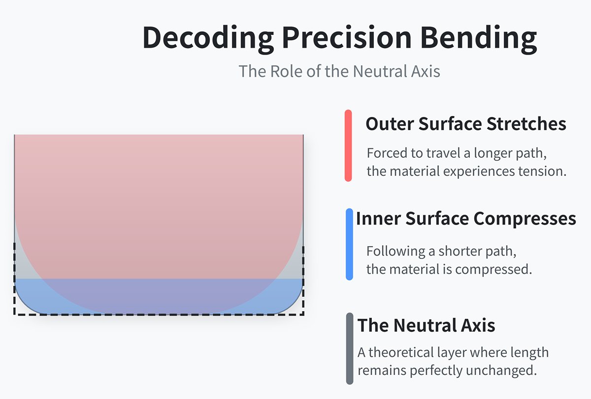
When a metal sheet is bent, the internal stress distribution is far from uniform. Picture the cross-section of a bent sheet:
- The outer surface of the bend stretches because it must travel a longer path.
- The inner surface compresses because it follows a shorter path.
Between these two opposing forces lies a theoretical layer whose length remains unchanged throughout the bending process. This remarkable layer is called the Neutral Axis.
Definition
What Is the Neutral Axis and How It Shifts During Bending In theory, the neutral axis is the region where both stress and strain are zero. For a flat sheet, it lies at the exact midpoint of the thickness. However, once bending begins, the compressive resistance on the inner side typically exceeds the tensile resistance on the outer side, causing the neutral axis to shift naturally toward the more stable energy state—the inner radius of the bend. This seemingly minor displacement is the key to all accurate flat pattern calculations.
The K-Factor: Predicting Material Stretching Behavior
To quantify the position of the neutral axis, engineers introduced a crucial dimensionless parameter known as the K-Factor.
K-Factor = Distance from the Neutral Axis to the Inner Surface (t) / Total Material Thickness (T)
- If the neutral axis is exactly at the mid-thickness, the K-Factor equals 0.5.
- Since the neutral axis shifts inward, the actual K-Factor is almost always less than 0.5, typically ranging from 0.33 to 0.48.
The K-Factor is not a constant—it depends on material type, thickness, hardness, bend radius, and the bending method. It serves as the essential “code” linking three-dimensional bend geometry to two-dimensional blank layout. Accurately setting the K-Factor in CAD or CNC systems is the first line of defense in ensuring precise flange dimensions.
3. Essential Terminology: Speak the Language of the Experts
By mastering the following industry terms, you’ll be able to describe issues precisely, interpret technical drawings correctly, and communicate seamlessly with experienced engineers.
(1) Bend Allowance (BA) vs. Bend Deduction (BD)
These two concepts represent different approaches to calculating the flat length of a sheet, ultimately leading to the same end result.
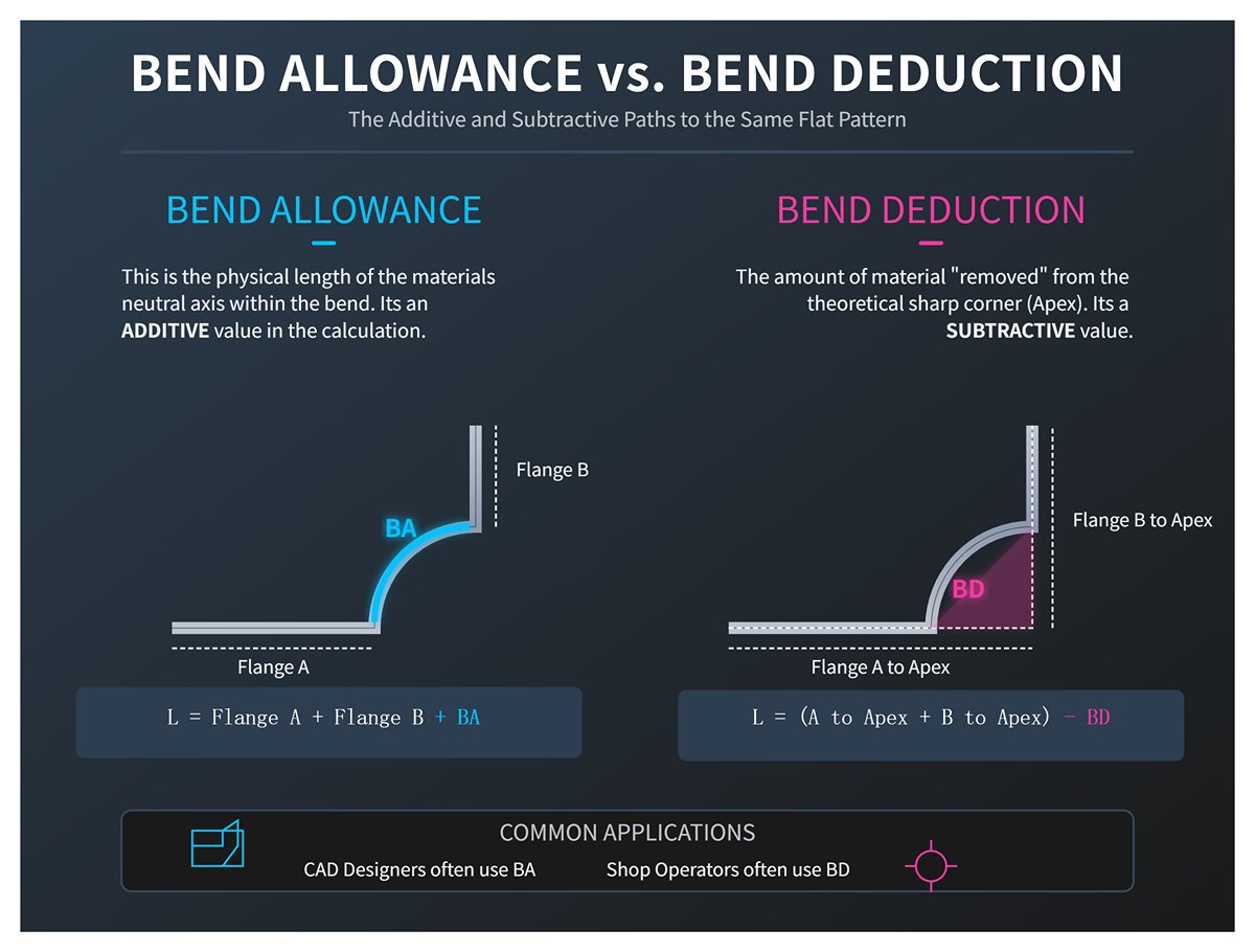
1)Bend Allowance (BA):
Refers to the arc length along the neutral axis in the bend region. You can think of it as the additional material length required to form the bend. The calculation follows an additive logic:
Flat length = Flange A length + Flange B length + Bend Allowance.
2)Bend Deduction (BD):
Refers to the amount subtracted from the total of two flanges extended to their theoretical intersection point (Apex) to obtain the correct flat length. The formula uses a subtractive logic:
Flat length = (Flange A to Apex) + (Flange B to Apex) – Bend Deduction.
In practice, designers typically work with BA values within CAD software, while shop-floor operators often use BD charts to quickly determine blank sizes.
(2) Springback
The metal’s “memory effect.” As explained earlier, once bending pressure is released, stored elastic energy within the material causes the bend angle to rebound slightly, resulting in a final angle greater than that of the tooling. For instance, to achieve a precise 90° bend, you may need to “overbend” using an 88° die to pre-compensate for springback. The stronger the material and the larger the bend radius, the more pronounced the springback.
(3) Minimum Bend Radius
This defines the smallest internal bend radius a material can tolerate without cracking on the outer surface. It reflects the material’s ductility. Any attempt to bend below this radius will overstretch the outer fibers and cause fractures, rendering the part defective. This value is typically expressed as a multiple of the material thickness (T)—for example, around 0.5T for soft aluminum and up to 3T or more for high-strength steels.
(4) Tonnage
The total forming force a press brake must apply to complete a bend, measured in tons. Applying the correct tonnage is critical: too little, and the bend cannot form properly; too much, and you risk damaging the tooling, machine, or leaving indentations on the part. Required tonnage depends primarily on material tensile strength, sheet thickness, bend length, and the width of the die opening (V-width).
4. Common Misconceptions: Avoid the Early Pitfalls
At the outset, some assumptions that appear “logical” can actually become the root cause of future errors. Let’s clear up these traps before they mislead you:
(1) Myth 1: The K-Factor Is Always 0.5 Clarification
This is one of the most frequent—and most serious—mistakes beginners make. The neutral axis always shifts inward, meaning the K-Factor is almost never exactly 0.5. Using that default value blindly will cause all flat pattern calculations to be fundamentally incorrect, leading to widespread dimensional errors in production.
(2) Myth 2: Coining Is the Ultimate Cure for Springback Clarification
While coining can virtually eliminate springback by applying extremely high pressure, it inflicts severe wear on the machine and tooling (requiring 5–10 times the tonnage of air bending) and can distort the material’s microstructure. In modern high-precision CNC bending, air bending—optimized through calculated overbending—has become the preferred method, balancing accuracy, efficiency, and cost-effectiveness.
(3) Misconception 3: If the final angle is correct, the part dimensions must also be correct
Clarification
Angle and dimension are two independent tolerances that must both be met. A part with incorrect flange length due to an erroneous K-Factor calculation is a reject, even if its bend angle is flawless. True professional bending achieves precision in both angle and dimension.
(4) Misconception 4: Material properties are perfectly consistent within the same batch
Clarification:
Even within a single coil of steel sharing the same batch number, slight variations in thickness, hardness, and chemical composition can occur. These inconsistencies are the main reason for dimensional and angular drift in mass production. This is precisely why modern high-end press brakes incorporate advanced features such as laser angle measurement and dynamic deflection compensation — to continuously counteract these variations and ensure consistent, repeatable accuracy.
Ⅵ. Simplifying Calculations: Turning Complex Math into Practical Power
We understand that for many beginners, seeing complex mathematical formulas can feel like hitting a wall. But rest assured — in the world of bending, these formulas are not obstacles; they are your most powerful tools. They bridge theory and practice, enabling precise control. The mission of this chapter is to “translate” these intimidating formulas into practical instruments you can understand, apply, and use to generate real value. Let’s break them down together, and make mathematics work for you.
1. Practical Calculation of Bend Allowance (BA) and Bend Deduction (BD)
As discussed in Chapter 2, Bend Allowance (BA) and Bend Deduction (BD) are the two core approaches to determining the flat pattern length for sheet metal parts. Mastering them allows you to predict exact formed dimensions right from the blank-cutting stage.
(1) Bend Allowance (BA) – the “addition” logic
Used when starting from the sum of straight segments and adding the length of the bend region.
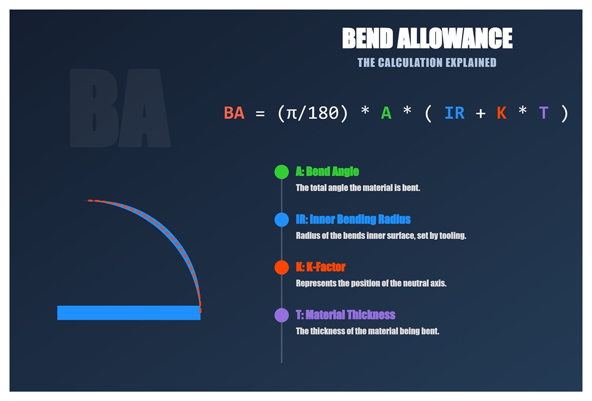
Formula: BA = (π / 180) * A * (IR + K * T)
Parameter breakdown:
A: Bend angle (for example, use 90 for a 90° bend)IR: Inner bending radius, determined by the punch radius or actual forming conditionsK: K-Factor, representing the location of the neutral axisT: Material thickness
(2) Final flat length
L = L1 + L2 + BA (where L1 and L2 are flange lengths)
(3) Bend Deduction (BD) – the “subtraction” logic
Used when starting from the total length extending to virtual intersection points and subtracting a correction value.
Formula: BD = 2 * OSSB - BA
(4) Outside Setback (OSSB)
OSSB = tan(A / 2) * (IR + T)
(5) Final flat length
L = (L1 to virtual intersection) + (L2 to virtual intersection) - BD
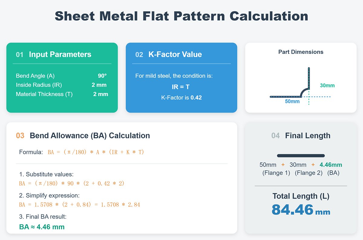
2. Case Study: Step-by-step calculation using common steel and aluminum
Scenario:
We need to bend a 90° part made of 2mm-thick mild steel. The drawing specifies an inner radius (IR) of 2mm, and the two flange lengths are 50mm and 30mm respectively.
(1) Determine parameters:
A = 90°IR = 2mmT = 2mm
Refer to the K-Factor table (see Section 3.2).
For mild steel, when IR = T, the approximate K value is 0.42.
(2) Calculate Bend Allowance (BA):
BA = (π / 180) * 90 * (2 + 0.42 * 2)BA = 1.5708 * (2 + 0.84)BA = 1.5708 * 2.84 ≈ 4.46 mm
(3) Calculate the flat pattern length:
L = 50mm + 30mm + 4.46mm = 84.46 mm
To produce a part with final flange dimensions of 50mm × 30mm, you should cut the flat blank to a total length of 84.46mm.
(4) Efficiency Tools: Recommended Online Calculators and Quick Reference Sheets
While understanding manual calculations is essential, efficiency is critical in fast-paced production environments. We strongly recommend bookmarking and using the following tools:
- Online Sheet Metal Calculators: Simply search “Sheet Metal Bend Calculator” — you’ll find numerous free tools that deliver instant results once parameters are entered.
- Mobile Apps: Many sheet metal industry apps come equipped with built-in BA/BD calculation features.
- Custom Excel Reference Table: Input the formulas into Excel to create your own model for commonly used materials and thicknesses.
Tools improve efficiency, but true mastery comes from understanding the principles. When tools fail or you face non-standard conditions, it’s that understanding that makes you the problem-solver.
3. K-Factor Quick Reference and Application Guide
The K-Factor is the cornerstone of all flat pattern calculations. An incorrect K-Factor can throw off the entire batch’s dimensions. Although the most accurate K-Factor can only be determined through test bending and back-calculation, the following industry-based reference table provides an excellent starting point.
(1) Typical K-Factor Reference Values (Air Bending)
| Material Type | Relationship Between Inside Bend Radius (IR) and Thickness (T) | Reference K-Factor Range |
| Soft Materials (e.g., Aluminum, Copper) | IR < T | 0.33 - 0.40 |
| IR = 1T to 3T | 0.40 - 0.45 | |
| IR > 3T | 0.45 - 0.48 | |
| Medium Hardness (e.g., Mild Steel) | IR < T | 0.38 - 0.42 |
| IR = 1T to 3T | 0.42 - 0.46 | |
| IR > 3T | 0.46 - 0.49 | |
| Hard Materials (e.g., Stainless Steel) | IR < T | 0.40 - 0.44 |
| IR = 1T to 3T | 0.44 - 0.48 | |
| IR > 3T | 0.48 - 0.50 |
(2) How to Accurately Unfold Sheet Metal Using the K-Factor
1)Identify the Material and Process:
Confirm the material type, thickness, and the specified inside bend radius according to the design drawing.
2)Estimate Using the Reference Table:
From the table above, select the K-Factor that best matches your material and bending condition.
3)Apply in Calculation:
Substitute this K-Factor into the BA or BD formula described in Section 3.1 to compute the flat pattern length.
4)Trial Bend Verification (Critical Step):
Perform a test bend on the first piece and accurately measure the flange dimensions. If there’s a deviation, fine-tune the K-Factor (reduce K if parts are oversized, increase K if undersized), recalculate, and retest until dimensions are precise.
5)Record and Archive:
Once an accurate K-Factor is established for a specific combination of material, thickness, radius, and tooling, record it meticulously. Build your own process database — an invaluable resource for efficient production in the future.
4. Essentials of Tonnage Calculation: Stop Guessing and Start Measuring
Setting press force based on intuition is one of the most dangerous habits for beginners. It can damage expensive dies and equipment and cause serious forming inconsistencies. Accurate tonnage calculation marks the line between a professional and an amateur.
(1) Basic Tonnage Formula and Key Variables (Air Bending)
A widely used estimation formula is:
Tonnage (tons) = [1.42 * σb * S² * L] / (1000 * V)
σb: Tensile strength of the material (MPa). For instance, Q235 mild steel is approximately 400 MPa.S: Material thickness (mm)L: Bend length (mm)V: Width of the lower die V-opening (mm)
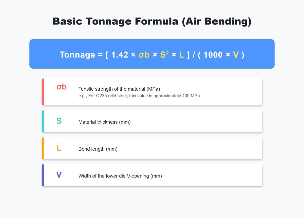
Key Insight: The tonnage required increases proportionally to the square of the material thickness! In other words, doubling the thickness leads to roughly four times the required press force.
(2) How to Read and Use a Tonnage Chart
In actual workshop operations, press brake operators usually rely on the Tonnage Chart provided by machine manufacturers — a simple and visual tool.
Steps to use:
1)Find the Correct Chart: Make sure you’re using the chart specific to your current material type (e.g., mild steel, stainless steel).
2)Locate the Material Thickness: Find your sheet thickness along the chart’s vertical or horizontal axis.
3)Locate the V-Opening Width: Find the width of the lower die V-opening along the other axis.
4)Read the Value: The intersection point of the two lines represents the tonnage required per meter of bend length.
5)Final Calculation: Total Tonnage = Tonnage per meter × Actual bend length (m)
6)Safety Warning: Never exceed your press brake’s rated maximum tonnage. Always maintain at least a 20% safety margin for your machine.
5. Calculating Minimum Bend Radius: The First Line of Defense Against Cracking
Designers may strive for sharp, compact bends, but pushing materials beyond their physical limits is every engineer’s nightmare. Any bend smaller than the material’s ductility limit will cause visible cracking along the outer surface, instantly rendering the part defective.
(1) Determining Factors for Minimum Bend Radius
Primarily dependent on the material’s ductility (or plasticity). The higher the ductility (e.g., soft aluminum), the greater the allowable deformation and the smaller the achievable bend radius.
(2) Typical Guidelines for Minimum Bend Radius (Expressed in Multiples of Material Thickness, T)
| Material Type | Condition / Grade | Recommended Minimum Inside Radius (IR) | Notes |
| Aluminum Alloy | Annealed (O) | 0.5T - 1T | Excellent ductility |
| Hardened (H) | 1.5T - 4T | Increases sharply with hardness | |
| Mild Steel | Q235, SPHC | 0.5T - 1T | Ideal for cold bending applications |
| High-Strength Steel | - | 2T - 6T+ | Follow data sheet precisely |
| Stainless Steel | 304 | 1.5T - 2T | Significant work hardening and springback |
| 316 | 2T - 2.5T |
(3) Ultimate Guideline
The values above offer valuable experiential reference, but the most reliable data always comes from the Material Data Sheet provided by the supplier. When working with unfamiliar, costly, or critical structural materials, consulting the data sheet is not optional—it’s a mandatory practice.
Also remember: Bending along the rolling direction of the sheet increases the risk of cracking—bends made perpendicular to the grain are less likely to fail. Whenever possible, orient your bend line perpendicular to the material grain.
A respected and irreplaceable expert in technical craftsmanship.
Ⅶ. FAQs
1. Why does springback occur during press brake bending, and how can it be controlled?
Springback occurs due to the elastic recovery of the material after the bending force is released. It is more pronounced in materials with higher yield strengths.
Factors influencing springback include:
- Material properties: Harder materials exhibit more springback.
- Bend radius and angle: Tighter radii and sharper angles increase springback.
- Bending method: Air bending, which does not force the material into the die, shows more springback compared to bottoming or coining.
Strategies to control springback:
- Over-bending: Slightly bending beyond the required angle to compensate for springback.
- Material selection: Choosing materials with lower springback tendencies.
- Precision-ground tools: Utilizing tools designed to account for springback.
- CNC adjustments: Modern CNC systems can dynamically adjust the bending parameters in real time to counteract springback.
2. What is the difference between air bending and bottoming in press brake bending?
Air bending and bottoming are two distinct methods used in press brake bending, each with unique characteristics and applications.
Air Bending involves positioning the workpiece over a die and using a punch to bend the metal without pressing it completely into the die. The material is not forced into the exact shape of the die, allowing for some degree of springback. This method is versatile and can handle a range of material thicknesses and bend angles using the same tooling. One of the primary advantages of air bending is its cost-effectiveness and flexibility, though it tends to be less precise compared to other methods due to the influence of springback.
Bottoming, also known as "bottom-dead-center bending," pushes the material all the way into the die, forcing it to conform closely to the die's shape. This method provides more precise control over the bend angle and results in higher accuracy and consistency. Bottoming requires more force than air bending and is generally used for applications where exact bends are critical. However, the increased force can lead to more wear on the tooling.
Ⅷ. Conclusion
Nowadays, press brake bending is indispensable for metal manufacture. This process is renowned for its long history, advanced technology, and widespread use, which makes it pivotal in various industries like aerospace, automotive, and construction.
The applications of CNC technology make the press brake bending significantly improved. It is essential for you to choose experienced manufacturers to delve into this technology and its back mechanical manufacturing.
As a leading company with over 40 years of press brake manufacturing experience, ADH Machine Tool can provide you with the most professional solutions and consultation. If you’re planning a new production line or need expert support, don’t hesitate to contact us for customized recommendations.