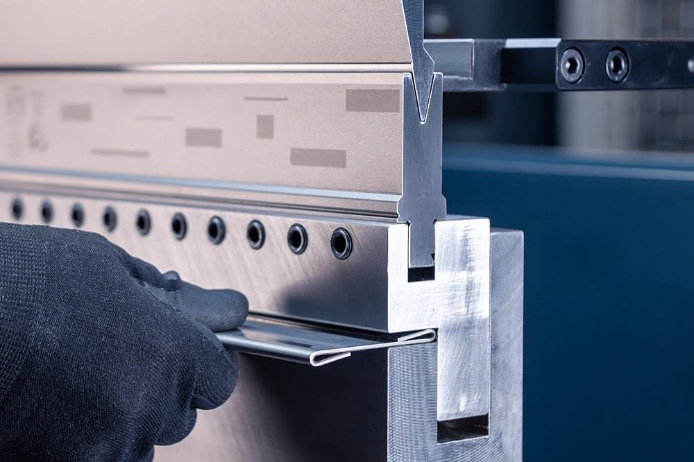
Mastering how to shim a press brake is the critical skill separating acceptable bends from perfect ones. If you're fighting the "canoe effect"—where angles are open in the middle—this guide provides the definitive system.
We move beyond guesswork into a repeatable science, covering everything from diagnosing deflection and LOTO safety protocols to executing the professional "Pyramid Technique" for dead-on accuracy every time.
I. Core Diagnosis: Why Are Your Bend Angles Always Tighter at the Ends and Wider in the Middle?
Few things are more frustrating than holding up a freshly bent long workpiece to the light and realizing it looks like a canoe—its ends crisp and sharp (say, 90°), while the middle sags open (perhaps 92°).
Before blaming your operator or suspecting tool wear, stop. This issue is not human error—it’s a battle against the immutable laws of physics. Before you slip in your first shim, you must first understand the underlying logic of this uneven contest.
1.1 Phenomenon Analysis: The “Canoe Effect” and the Physics of Deflection
What we call the “Canoe Effect” is, in engineering terms, the truth of structural deflection: the side frames of a press brake are its most rigid anchors and move almost imperceptibly, while the center—furthest from these supports—is the weakest point. Under high bending loads, the upper beam bows upward while the lower bed deflects downward.
- The Invisible “Jaw Opening”: The deformation isn’t purely vertical. The C‑shaped side frames also exhibit a subtle outward “yaw” when under stress. Combined, these distortions create the widest die space right at the machine’s center.
- The Consequence: Even a 0.05 mm gap difference at the center is enough to reduce bending depth, causing springback and resulting in a wider angle in the middle.
Key Insight: Deflection follows a dynamic curve. On the same machine, deflection may be negligible when bending a 1‑meter thin sheet, but it grows exponentially when handling a 3‑meter thick plate. Worse still, if the material itself has a thickness tolerance—say, slightly thicker in the middle—this small variation aligns with the machine’s weakest zone, amplifying the error into a visibly warped part.
1.2 The Essence and Value of Shimming
Shimming is not a crude patch-up fix—it is the precision art of manually constructing a counter‑deflection curve.
- Essence: Physically, shimming means intentionally “raising” the center of the lower die. By inserting materials of varying thickness beneath different sections of the die, we create a convex curve—high in the middle, low at the ends. When the press naturally deflects under load, this artificial curve cancels out the sag, keeping the die tip parallel to the sheet across the entire length.
- Value:
- Zero Capital Investment: It requires no costly hydraulic or mechanical systems—just a few sheets of paper or metal foil can restore precision to an aging machine.
- A Lifesaver for Specific Scenarios: Ideal for long, repetitive jobs or temporary prototyping tasks where efficiency matters most.
- Micron-Level Control: Skilled technicians can often achieve finer local adjustments than some automated compensation systems.
However, remember that a shim represents a static curve. It cannot adapt to changes in tonnage. Once you change material thickness, type, or die length, your previously perfect setup may instantly lose accuracy. In essence, shimming is a manual simulation of what CNC systems achieve automatically through dynamic compensation.
1.3 The Strategic Choice: Shimming vs. Mechanical Crowning vs. Hydraulic Crowning
Before spending hours on shimming, you need to understand its place within the modern accuracy ecosystem. These three methods aren’t direct substitutes—they’re strategic options for different production contexts:
| Characteristic | Shimming | Mechanical Crowning | Hydraulic Crowning |
|---|---|---|---|
| Working Principle | Manual layering under the die | A set of wedges move against each other beneath the bed | Hydraulic cylinders lift the bed from below |
| Accuracy & Control | Highly dependent on operator skill | Extremely precise, continuously adjustable curve | High, with CNC‑calculated compensation |
| Repeatability | Low – must readjust with every die change | Very high – parameters can be saved and reused | Medium‑high – affected by oil temperature and leakage |
| Ideal Use Case | Long, low‑volume runs, older machines, limited budgets | High‑precision, frequent changeovers, complex jobs | General machining, high automation environments |
| Main Drawback | Time‑consuming, risk of over‑shimming and die damage | Mechanically complex; wedge wear requires maintenance | Subject to drift – an inherent hydraulic limitation |
Decision Guidance: If your workshop mainly produces large batches of long parts or operates classic machines without compensation functions, mastering shimming is a survival skill. But if you’re switching between multiple products daily and demand high precision, the time cost of shimming becomes a bottleneck—upgrading to a mechanically crowned bed is the smarter long‑term investment.
Now that you understand your real adversary—machine deflection—it’s time for hands‑on practice: how to build that perfect counter‑curve safely and scientifically.
II. Preparation Phase: Sharpen Your Tools Before You Strike
In many workshops, I’ve seen operators instinctively grab scrap paper and stuff it under the die the moment they notice angle deviations. This reflexive habit is the enemy of precision. Before constructing a compensation curve, you must follow a process as meticulous as a surgical operation.
The goal of this stage is clear: eliminate interfering variables, select the right materials, and ensure you complete the task safely and effectively. To better understand the fundamentals of press brake operation, you can explore practical guides like how to shim a press brake for deeper insight.
2.1 Diagnose Before You Disassemble
Before trying to correct deflection with shims, confirm that deflection is truly the issue—not a symptom of mechanical damage. Shims are meant to counter physics, not to conceal neglect in maintenance.
- Zero‑Point Cleaning: This is the foundation of all precision. Micron‑level shimming tolerates no dust or debris. Thoroughly clean the die holder and bed surfaces— even a single metal chip or a film of hardened grease can create a false height of 0.05 mm, invalidating all subsequent adjustments.
- Check for “Ram Upset” (Permanent Deformation): This often‑overlooked culprit can mimic deflection. If your machine has spent years over‑loading short parts at the center, the ram may have undergone permanent plastic deformation—a subtle but deadly sag.
- Quick Diagnostic Method: Raise the ram and stretch a piece of high-tensile fishing line or piano wire tightly across the left and right edges of the ram’s underside. Use a feeler gauge to measure the gap between the wire and the center of the ram’s bottom surface. If the center gap is significantly larger than at the ends (for example, more than 0.1 mm), it means the ram has developed a permanent sag—what we jokingly call a “permanent smile.” In this case, shimming merely fills the damage rather than compensating for elastic deflection.
- Mold Condition Assessment: Examine both the upper and lower dies for uneven wear. If the shoulder radii show irregular abrasion or if linearity has exceeded tolerance, shim calibration will turn into an endless “patch one side, break the other” cycle. For those new to these inspection procedures, ADH Machine Tool offers professional resources and technical insights to help identify and correct mechanical deviations effectively.
2.2 Materials Science: Choosing and Debating Shim Materials
A shim is more than just a filler—it’s the medium through which tonnage is transmitted. Selecting the wrong material is like building on sand: the foundation will slowly sink over time.
- Paper Shims: A Convenient Trap: This is perhaps the most debated topic in the field. Ordinary printer paper (around 0.1 mm) or sticky notes (roughly 0.08 mm) are widely used because they’re easy to find. However, as a professional, you must understand their fatal flaw—compressibility. Under heavy tonnage, paper fibers collapse, meaning the actual compensation is less than the theoretical thickness. Moreover, paper absorbs hydraulic oil and coolant like a sponge, causing it to swell and eventually decay.
- Expert Tip: Paper shims should be used only temporarily for setup or small, non-repetitive production runs. For any long-term job, discard them immediately.
- Metal Shim Stock: The Industrial Gold Standard: For processes that demand absolute stability, brass or stainless steel shims are the only real choice.
- Incompressibility: Metal shims maintain a constant thickness even under tens of tons of pressure, ensuring a perfectly linear transfer of compensation.
- Standardized Thickness Coding: Industrial shim stock is often color-coded by thickness (for example, blue for 0.05 mm, brown for 0.10 mm), making documentation and reuse straightforward.
- Laminated Shims: The secret weapon of seasoned technicians. These are made of multiple bonded metal foils, each as thin as 0.05 mm. Operators can simply lift layers with a blade—like peeling an onion—to fine-tune thickness. This design combines the rigidity of metal with the flexibility of paper. To explore available shim materials and technical specifications, download the latest brochures from ADH Machine Tool.
2.3 Tool Kit and Safety Lockout (LOTO)

Shim calibration requires the operator’s hands and head to remain for extended periods in the machine’s most dangerous zone—the pinch point. Here, even the slightest lapse in attention can lead to irreversible injury.
- Essential Precision Toolkit:
- Micrometer: Ditch your calipers. When measuring shim thickness, you need 0.001 mm resolution, not a rough 0.02 mm estimate.
- Marker and Tape: Use these to mark the centerline (CL) and shim placement points on the lower die holder. It may seem trivial, but it’s critical for maintaining repeatable accuracy.
- Your Lifeline: LOTO and Physical Support: Never trust the hydraulic system. Even when power is off, aging seals or leaking valves can cause the ram to slowly descend under its own weight—a phenomenon known as gravity drift. This movement is often imperceptible until it’s too late.
- LOTO Procedure: Always perform a full Lock-Out/Tag-Out—disconnect the main power and lock the control cabinet.
- Physical Safety Blocks: This is non-negotiable. Before reaching into the die area, always insert rated safety blocks between the ram and the worktable. That solid metal column is your last line of defense—it physically prevents the ram from descending.
Once everything is ready—the machine cleaned and inspected, metal shims cut to specification, and safety blocks securely in place—you’re finally prepared to chase micron-level precision. For further operational guidance, check the step-by-step tutorial on how to shim a press brake. Next, we’ll move to the core of the operation: the Pyramid Stacking Technique.
III. Hands-On Practice: The Exclusive “Pyramid Technique”
At this stage, we’ve reached the very heart of the calibration process. Many inexperienced operators rely on instinct—adding shims wherever they see a dip—which often results in uneven stress distribution or even die breakage.
Professionals take a completely different approach: the Pyramid Technique. This isn’t about merely filling gaps; it’s about engineering a manually constructed parabolic curve that counteracts the press’s natural deflection.
3.1 Surface Preparation: The Foundation of Micron-Level Accuracy
Before placing your first expensive brass shim, you must perform a near-obsessive level of surface cleaning. Under tens of tons of hydraulic pressure, even a speck of metal dust or a smear of hardened oil can act as a random “rigid point.” Not only will this ruin your precision calculations, but it can also leave permanent dents in the die base.
- Absolute Cleanliness: After removing the lower die, don’t just wipe it casually with a rag. Use industrial alcohol or acetone with lint-free nonwoven cloth to thoroughly clean the die holder grooves and die bottom. Remove all traces of old tape, oil, and crystallized coolant.
- The Fingernail Test: A time-honored trick among veteran technicians. Close your eyes and lightly run your fingernail across the cleaned surface. Human touch is remarkably sensitive—if you feel any drag or graininess, the surface flatness isn’t yet acceptable. When needed, gently dress burrs with an ultra-fine oilstone (at least 1000 grit), but work delicately to avoid altering the original flatness.
3.2 Core Procedure: Building the Reverse Compensation Curve
The essence of the Pyramid Technique lies in recreating the continuous curve of machine deflection—not forming abrupt steps. Simply placing a thick shim at the center creates a dangerous stress riser, which can easily cause die cracking. What we want instead is a smooth, arch-like transition.
- Locate the Epicenter: Using data from your previous test bends, identify where the angle deviation is greatest—usually at the press’s geometric center or the midpoint of the bending zone.
- Layering Strategy:
- Base Layer: This forms the foundation of the pyramid. Using the epicenter as your midpoint, lay a strip of shim covering roughly 60%–70% of the deviation zone. For example, if the deviation zone spans 1 meter, your base layer should be about 600–700 mm long.
- Middle Layer (The Body): Place a shim on top of the base layer with a length about two-thirds that of the base. This layer provides the main structural rigidity.
- Top Layer (The Peak): At the very center, add a short shim whose length is roughly one-third that of the base layer.
This "wide–medium–narrow" configuration allows each layer’s edges to undergo slight elastic deformation under load, forming a smooth convex curve. This ensures that the working pressure is distributed evenly along the entire die length rather than concentrated at a few points. For advanced examples of this technique, refer to how to shim a press brake.
3.3 Thickness Calculation and Empirical Formula
Many operators shy away from shim calibration simply because they don’t know how thick the shim should be. While exact values involve complex material mechanics, in real-world practice we can rely on an empirically proven rule of thumb validated through countless applications.
- Golden Rule: For standard carbon steel bending, each 0.1mm (≈0.004 inch) of shim thickness typically corrects about 1° to 1.5° of bending angle.
- Note: This value is inversely proportional to the die’s V-opening width. The wider the V, the smaller the correction effect for the same shim thickness; the narrower the V, the more sensitive the correction.
- Quick Estimation Formula: For more precise control, use the formula: T ≈ Δα × K. Here, T is the required total shim thickness, Δα is the angular deviation, and K is a coefficient (typically 0.05–0.08 for narrow V-openings and 0.1–0.15 for wide ones).
- “50% Starting Principle”: Regardless of the theoretical thickness you calculate, insert only 50% of that value for the first test. For example, if your calculation suggests 0.2mm, start with 0.1mm. The reason is simple: in this process, adding more shims later is always safer than over-shimming, which can damage the die or cause overbending. It’s better to make two or three fine adjustments to reach perfection than to risk failure in one go.
3.4 Fastening and Resetting: The Overlooked Critical Steps
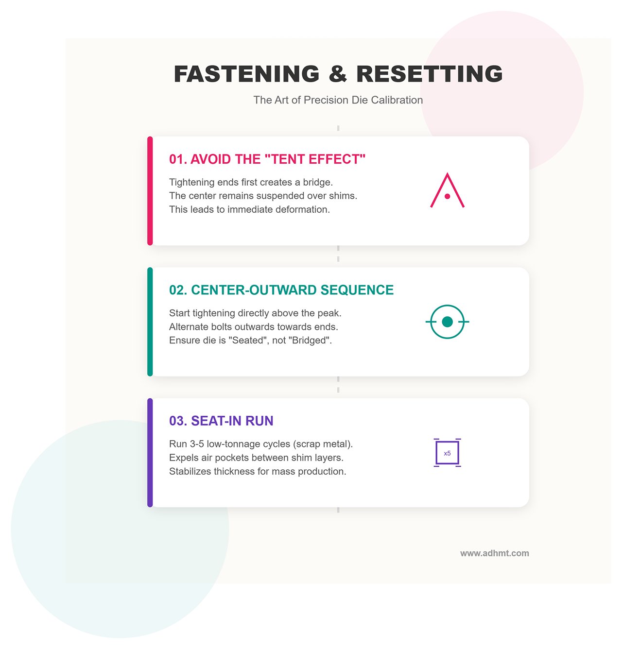
Placing the shims is only half the job; the way you clamp the die determines the final result. Many beginners tighten the bolts from both ends toward the center—this is strictly prohibited in shim calibration.
- Avoiding the “Tent Effect”: If you tighten both ends first, the die will rest like a tent over the shim stack, leaving the center suspended. Once pressure is applied, the die will deform abruptly.
- Correct Tightening Sequence: Always follow the “center-outward” principle. Start by gently tightening the bolt directly above the peak of the shim “pyramid,” ensuring the die bottom conforms tightly to the shim curve. Then alternately tighten bolts toward both ends. This keeps the die “seated” on the curve instead of “bridged” over it.
- Seat-in Run (Empty Load Conditioning): Before bending actual material, perform 3–5 low-tonnage press cycles (you can even use scrap for shallow bends). This step expels micro air pockets between shim layers and allows the metal shims to reach their final stabilized thickness under pressure. Only after this “settling” process can your calibration maintain accuracy during mass production.
IV. Verification and Fine-Tuning: The Art of Closed-Loop Optimization
Don’t get carried away by the first bending result after assembling your “pyramid.” The physical world is full of nonlinear factors—placing shims marks only halfway to success. Verification and fine-tuning are the steps that turn “almost right” into “perfect” and transform luck into science.
4.1 Second Trial and Data Analysis: Rejecting Single-Point Validation
After placing the shims and securing the die, perform a second test bend (Verification Bend). Here lies a crucial principle that separates novices from masters: never measure only the center point.
Many operators start production as soon as the center angle reads 90°, forgetting that stress redistribution may cause anomalies at both ends. You must use the “Three-Point Measurement” method—and for workpieces over 3 meters long, even five-point measurement is advisable.
- Logic Behind the Three-Point Rule:
- Measurement Points: Record the angle readings precisely at the far left, center, and far right positions of the test piece.
- Ideal Condition: All three points should show identical angles (e.g., 90.0°) or remain within the client’s tolerance range (such as ±0.2°).
- Beware of the “Reverse Canoe Effect”: This is the most common sign of over-adjustment. If both ends read 90° but the center shows 88° (overbent), your shims are too thick or too many. The center has turned into a “negative deflection” zone, pushing the die up excessively. This not only risks damaging the sheet but also causes long-term concentrated stress on the ram’s center.
- Building a Machine Fingerprint Archive: Don’t let your hard work be a one-off achievement. Every successful shim calibration is a piece of code cracked from your machine’s behavior. Create a simple “machine fingerprint sheet” to record key data:
- Operating Parameters: Sheet thickness, material type, bending length, and applied tonnage.
- Solution Details: Shim material, total thickness, and distribution pattern (ideally with a small sketch—for example: center shim 0.15mm, left/right shims 0.10mm placed 200mm from center).
- Final Deviation: Angle differences between left, center, and right points.
Next time you encounter similar working conditions, you can consult this archive and reduce hours of trial-and-error to just minutes of execution. If you encounter unique machine behaviors or need expert evaluation, you can always contact us for customized technical support.
4.2 Considering Dynamic Factors: The Invisible Variables Behind Shifting Angles
Sometimes you’ll face a puzzling situation: everything was perfectly calibrated in the morning, but after lunch, the angles drift off. Don’t rush to remove the shims—you may be dealing with invisible “dynamic variables.” Before declaring shim failure, investigate these three “ghosts”:
- 1. Hydraulic Oil Thermal Drift: This is the most subtle accuracy killer.
- Phenomenon: In the morning, oil temperature may be around 15°C; during continuous production it can rise to 45°C or higher. The drop in viscosity increases micro leakage, altering pressure distribution transmitted to the ram.
- Countermeasure: Never perform precision shim calibration with a cold machine. Always run a mandatory Warm-up Cycle, letting the ram travel its full stroke for 10–15 minutes until the oil stabilizes within the normal operating range (typically 35–40°C). Only then should you proceed with measurement and fine-tuning.
- 2. Material Consistency Trap: Shims can compensate for machine deformation, but they cannot fix inconsistencies in the material itself.
- Thickness Tolerance: Within the same bundle of sheets, a thickness variation of 0.006 inches (approximately 0.15 mm) may meet industrial standards—but in precision bending, that fluctuation can produce angle deviations of 2 to 4 degrees. If your test piece happens to be slightly thicker than your production batch, your shim calibration will fail.
- Grain Direction: Bends made along the grain and across the grain exhibit distinctly different springback behaviors. Always ensure that the grain orientation of your test piece matches the production material exactly.
- 3. The Subtle Effect of Dwell Time: This is a frequently overlooked parameter. When the ram pauses at the bottom dead center for 0.1 seconds versus 0.5 seconds, the resulting bend angles in materials with high springback—such as stainless steel or high-strength alloys—can differ significantly.
- Countermeasure: Make sure the dwell time you set during testing matches exactly the dwell time programmed for mass production. Do not attempt to verify shim effects through manual jogging; validation must be performed using the CNC’s automatic cycle.
Through this closed-loop logic—from physical diagnostics to pyramid compensation to dynamic fine-tuning—you’re not merely repairing a machine; you’re mastering the raw behavior of metal itself. For more advanced press brake solutions and technical consultation, visit ADH Machine Tool. Remember: shim calibration is not just inserting thin sheets—it’s a physical manifestation of deep understanding of the bending process.
V. Advanced Strategies and Common Pitfall Analysis
Precision bend calibration is never a “set it and forget it” achievement—it’s a dynamic equilibrium. Over years of field experience, I’ve seen countless veteran technicians lose hours to futile shim adjustments because they ignored systemic variables.
To evolve from a simple “fixer” to a true “process control master,” you must learn not only how to place shims, but when not to—and how to turn isolated successes into repeatable standards.
5.1 The Top 5 Pitfalls to Avoid

When trying to conquer the deflection curve, the following five traps can swallow your production time—and in severe cases, cause irreversible damage to expensive machinery.
- Over-Shimming: A Narrow Bridge to Fracture — This is the most common and dangerous mistake. When deflection becomes excessive, operators tend to keep stacking shims. However, overly thick shim packs (typically above 0.5–0.8 mm) change the contact between the die and the bed from a uniform surface to isolated points.
- Physical Consequence: At that point, your lower die holder is no longer evenly supported—it’s suspended like a bridge resting on shim piles. Under hundreds of tons of pressure, this stress concentration can easily cause permanent bending of precision die seats, or even catastrophic fracture.
- Red Line Warning: If you need more than 0.5 mm of shim to correct an angle, stop immediately. This indicates an underlying issue—uneven foundation, severe ram wear, or structural damage to the machine bed. Continuing to shim only hides the real cause.
- Confusing Ram Tilt with Deflection: Not all angle inconsistencies are caused by deflection. If your measurements show 88° on the left, 92° on the right, and 90° in the middle, this is not a problem shims can fix.
- Diagnostic Logic: Shims correct linear deviations (center vs. ends), while ram tilt correction addresses balance deviations (left vs. right).
- Proper Countermeasure: Put down the shims and use the CNC system to calibrate the Y1/Y2 axis level—or mechanically adjust the top stop blocks of the ram.
- The “Ghost Tonnage” Trap: You may have set the machine to 100 tons—but did it actually deliver that force? If the hydraulic system suffers internal leakage or if a proportional valve sticks, real output could be only 80 tons.
- Chain Reaction: Deflection is proportional to tonnage. If you shim based on a theoretical 100-ton deflection but the machine only delivers 80 tons, you’ll overcompensate—creating a “reverse canoe effect” where the center is tighter than the ends. Always verify pressure gauge readings before performing any calculations.
- The “Princess and the Pea” Effect (Dirty Assembly Hazard): Under hundreds of tons of clamping force, even a metal chip the thickness of a hair can press a permanent divot into a precision-ground die seat.
- Invisible Killer: That tiny divot becomes a permanent accuracy gap. Even without shims, the tool height at that location will forever be short by 0.05 mm.
- Execution Standard: Before placing shims, always clean contact surfaces with industrial alcohol and a fine oilstone. If you can feel any grit with your fingertips, never proceed to closing the dies.
- Misjudging Material Springback: Shim calibration corrects the machine’s geometric straightness—not the material’s physical springback. If some pieces in the same batch have larger middle angles while others are smaller, the cause is typically uneven hardness or thickness variation in the sheet—not a machine fault.
- Key Distinction: Only when 5–10 consecutive parts consistently show the same “center angle too large” pattern should shim calibration be initiated. Trying to chase dynamic material tolerances with static shims is a futile exercise.
5.2 Long-Term Maintenance and Standardization
To avoid turning every die change into a guessing game, you need a standardized maintenance system that converts individual experience into shared workshop assets.
- Building a “Shim Map”: Don’t let your perfect shim setup get discarded after the order is complete. For recurring long-part production, establish a standard operating procedure (SOP):
- Recording Parameters: Document mold type, bend length, tonnage, and the exact shim configuration (e.g., Centerline shim 0.15 mm; 0.10 mm shims placed 300 mm to each side of CL).
- Visualization: Draw a simple chart and attach it to the job sheet. Next time, the operator can follow the diagram directly—reducing setup time from one hour to five minutes.
- Tool Rotation Strategy: Most bending operations concentrate near the center of the machine, causing the middle section of tooling to wear much faster than the ends. This wear can masquerade as deflection, misleading you into unnecessary shim adjustments.
- Maintenance Tip: Make it a habit to periodically (e.g., quarterly) flip the lower die rail or reverse the die seat orientation. For segmented dies, regularly reshuffle their order to equalize wear across the full length.
- Hydraulic System “Heart Health”: The temperature and cleanliness of hydraulic oil directly affect pressure stability—and pressure determines deflection.
- Benchmark: Replace the hydraulic oil every 2,000 operating hours and clean the filters regularly. Even the most refined shim configuration becomes meaningless if the hydraulic system delivers unstable pressure.
By avoiding these common pitfalls and establishing a standardized maintenance routine, you’ll evolve from a constant “firefighter” to a true “process commander” who controls precision at the micron level. Remember, shims are merely a tool—consistent geometric accuracy is the ultimate goal.


