How to properly shim air bending press brake dies is not just a maintenance trick; it is a precision process that often decides whether a machine can reliably hold tight angular tolerances across the full length of a part.
Behind what looks like a few scraps of metal under a die are hard limits set by ram and bed deflection, the “canoe effect,” and the extreme depth‑to‑angle sensitivity of air bending. This article builds a complete roadmap from first‑principles physics, through diagnostic mapping and material choice, to standardized installation methods, hybrid compensation strategies, and long‑term shim management, so that every adjustment is deliberate rather than trial‑and‑error.
I. Foundational Understanding: Building a Precision Calibration Mindset
Before diving into the specifics of shim placement techniques, we must first correct a common misconception: shimming is not a simple “fill where it’s low” patchwork job. It is a form of precision mechanical compensation grounded in the principles of physics. Without a solid grasp of its underlying mechanics, even the most expensive shims won’t save you from a high scrap rate.
1.1 The Physical Challenge of Air Bending: Why Shims Are Necessary
The defining feature of air bending lies in its “floating” nature. The bend angle depends entirely on how deeply the ram presses into the die, rather than on any rigid contact with the die bottom. This forming method is extremely sensitive to the machine’s geometric precision, and physics dictates that no press brake can ever be perfectly rigid.
- Machine Deflection and the ‘Canoe Effect’ When pressures ranging from several to hundreds of tons are applied to the sheet, the machine inevitably undergoes elastic deformation: the upper ram is forced downward by hydraulic cylinders while the center bows upward under reactive force; the lower bed, in turn, deflects downward. This phenomenon—“ram arching upward, bed sagging downward”—creates a microscopic gap that is wider in the center and narrower at the ends. The resulting bend often produces a part with a slightly raised center and lower ends, resembling the keel of a canoe, hence the term “Canoe Effect.”
- Result: The ends of the part bend more deeply, producing smaller angles (overbending), while the center bends less due to the larger gap, yielding larger angles (underbending).
- Micron-Level Sensitivity In air bending, depth equals angle. A mere 0.01 mm depth error can lead to an angular deviation of 0.5° to 1°, depending on the die’s V-opening. Thus, even a tiny machine deflection of 0.1 mm at the center can cause several degrees of difference between the middle and the ends. The purpose of shimming is to eliminate such micron-scale depth variations caused by structural deformation. For a deeper understanding of this principle, you can explore how to properly shim air bending press brake dies for practical illustrations.
1.2 Core Definition and Positioning of Shimming
Shimming is not about concealing machine defects—it is a deliberate, physics-based intervention designed to counteract natural mechanical behavior.
- Technical Definition: Creating a “Reverse Deflection Curve” Professional shimming essentially constructs a “reverse deflection curve” beneath the die holder. Since the machine tends to sag in the middle under load, shims are arranged to create a slight convex shape there. When pressure is applied, the machine’s concave deflection and the shim’s convex compensation balance each other, keeping the upper and lower dies dynamically parallel across their entire length under full load.
- Decision Boundary: When to Use Shims Not every error can be corrected with shims. Clear boundaries must be established:
- Appropriate Use: Shims are mainly used to compensate for elastic deformation under load (center angle larger, ends smaller) or on machines lacking CNC crowning compensation. They can also address minor localized wear from long-term, fixed-position tooling.
- Inappropriate Use (Requires Regrinding): When dies show visible dents, chipped edges, or severely worn shoulder radii, shims cannot restore geometry and regrinding is mandatory.
- Inappropriate Use (Requires Leveling): If angular deviations follow a linear slope—for instance, consistently larger angles on one side—it indicates misalignment between the ram and bed. The machine’s feet or hydraulic leveling must be adjusted. Attempting to “fix” it with shims is strictly forbidden, as it can severely damage the ram guides.
1.3 Common Misconceptions Clarified

On the shop floor, shims are often misused as a quick fix—an approach that stems from three critical misunderstandings:
- Misconception 1: ‘Just Use Paper’Reality: Torn A4 sheets or cigarette boxes are the enemies of precision. Paper is made of organic fibers that deform unpredictably under heavy pressure through compression creep. The first part may pass inspection, but over time the paper thins and the bend angles drift.
- Correct Practice: Always use industrial-grade brass or blue-tempered spring steel shim stock. These materials have defined compression modulus values, ensuring the same bending accuracy months later as on day one.
- Misconception 2: ‘Shims Fix Everything’ Reality: Many operators add shims blindly without first checking the machine’s condition. If the foundation has settled or the ram’s repeatability is poor, shims merely mask deeper problems, shifting the load center and increasing the risk of die failure. “Diagnose first, shim later” is an unbreakable rule.
- Misconception 3: ‘Raise the Entire Length’Reality: Seeing a poor angle in the center, some operators place a full-length shim under the die. This is a useless placebo—it only raises the reference surface (essentially re-zeroing the tool) without altering the deflection curve. The “Canoe Effect” remains unchanged.
- Correct Practice: Effective shimming must be sectional and tapered—thicker in the center, gradually thinner toward the ends—to physically redistribute the load and counteract deformation. For step-by-step visuals, check how to properly shim air bending press brake dies.
II. Diagnosis and Preparation: Before Inserting the First Shim
Once the physics of air bending are fully understood, many operators instinctively reach for shims to start “filling gaps.” That’s a major mistake. Shimming is a precision compensation process, not a trial-and-error experiment. If the machine’s baseline condition is faulty or if measurement data is misleading due to poor sampling, any shim strategy will be futile. Before touching the first shim, a rigorous diagnostic and preparation process is mandatory.
2.1 Systematic Error Elimination: The Pre-Shimming Checklist
Shims are designed to counter mechanical deflection and minor wear, not to repair mechanical failures. Using them on a malfunctioning press brake compromises accuracy and can accelerate damage to the ram guides. Before proceeding, perform this essential “health check”:
- Ram Repeatability Test Shims cannot correct random error. If your bend angles fluctuate unpredictably, first rule out hydraulic system or encoder issues.
- Procedure: Set a fixed depth and perform five consecutive air bends without a workpiece, observing the dial indicator at bottom dead center.
- Evaluation: If readings vary by more than 0.02 mm, the hydraulic valves are unstable or mechanical clearance is excessive. Call maintenance before attempting any shimming.
- Parallelism Trap Identification This is the most frequently misdiagnosed issue.
- Symptom Recognition: If the full-length test bend shows a linear angular deviation (e.g., left end 90°, center 91°, right end 92°), this is not deflection—it indicates the ram and bed are out of parallel alignment.
- Strictly Prohibited: Never attempt to correct linear deviation by inserting step-like shims such as “thin on the left, thick on the right.” This will twist the ram under load and can cause severe damage to the guide rails.
- Proper Solution: Adjust the machine’s mechanical zero point (Y1/Y2 axis data) or fine-tune the wedge blocks. Level the machine first—only then should you discuss shimming.
- Shoulder Radius Inspection: Repeated bending of short workpieces at a fixed position can create small, localized “micro-pits” on both sides of the lower die’s V-opening.
- Assessment: Examine the shoulder radius along the V-opening. If the wear depth at any point exceeds 0.05 mm, that location will produce a permanent angular deviation of roughly 0.5°. This kind of “geometric defect” can only be corrected by regrinding—shims cannot compensate for lost material.
2.2 Data Mapping and Error Visualization
Many experienced technicians test with three small pieces—placed at the left, center, and right of the machine. In precision calibration, this method is completely incorrect. Separate samples cannot replicate the continuous tension a full-length sheet places on the frame, nor can they reveal the true deflection curve under full load. What you need is a comprehensive “error topography.”
- Full-Length Test Bend
- Material Preparation: Use a test piece equal in length to the machine’s bed (e.g., a 3‑meter sheet for a 3‑meter press). The material must be uniform—cold‑rolled steel (SPCC) is highly recommended. Avoid hot‑rolled plates with uneven thickness, which can distort diagnostic results.
- Pressure Setup: Set the press to about 80% of its typical operating tonnage and target a 90° bend. Crucial point: maintain pure air bending—never bottom out. You can refer to how to properly shim air bending press brake dies for additional setup guidance.
- Grid Measurement Strategy
- Grid Layout: After bending the test piece, mark measurement points every 150–300 mm with a marker. For a 3‑meter workpiece, collect at least 10–15 data points—three points are far too few.
- Data Recording: Measure each point using a high‑precision digital protractor and record the results in Excel or on a drawing.
- Interpreting the Error Map: Connect the angle deviations into a curve; you will typically observe one of two patterns:
- “U”-Shaped Curve: A classic sign of deflection—larger angles (wider openings) in the center and smaller angles at the ends. This is the ideal zone for shim adjustment.
- “W”-Shaped Curve: Indicates possible localized wear or complex deformation caused by the support‑point design of older machines.
- Golden Rule of Thumb: How do you translate angle variation into shim thickness? For a standard V‑die (V = 8 × sheet thickness), the general empirical formula is:
0.1 mm (approximately the thickness of one A4 sheet) shim ≈ 1° change in bend angle
Note: The smaller the V‑opening, the higher the sensitivity; larger V‑openings reduce sensitivity.
2.3 Shim Material Science and Tool Preparation

To achieve precision, you must first prepare your tools. The most important step is to discard any scrap paper or cigarette boxes nearby. Under hundreds of tons of repeated hydraulic impact, non‑industrial materials are physically unstable and are the main reason your “perfect adjustment” keeps shifting.
- Material Selection
- Industrial‑Grade Preference: Always use professional‑grade 1095 blue‑tempered spring steel or C26000 hard brass.
- Key Advantages: These materials offer extremely high compressive strength (steel > 500 MPa) and will not experience compression creep under long‑term heavy loads. This ensures your bending precision remains identical even months later. You can download detailed material specifications from our brochures.
- Temporary or Transitional Media: High‑quality kraft paper or polyester shims may be used for micro‑adjustments (<0.05 mm) or as the topmost “feathering” layer to smooth hard transitions between metal shims.
- Strictly Forbidden:
- Regular A4 Paper: Loose fibers make thickness unpredictable under pressure.
- Transparent Tape: The adhesive layer flows under pressure, gradually thinning over time and leaving difficult‑to‑remove residue.
- Industrial‑Grade Preference: Always use professional‑grade 1095 blue‑tempered spring steel or C26000 hard brass.
- Establishing the Sensitivity Coefficient (Calibration): While the rule of thumb is “0.1 mm ≈ 1°,” achieving master‑level precision requires a sensitivity test:
- Insert a standard 0.10 mm steel shim at the exact center of the die.
- Perform a single test bend and measure the angle change, Δα.
- Calculate the current machine‑die sensitivity coefficient K: K = 0.1 / Δα (mm/degree).
- For all subsequent shim calculations, use: T = target angle difference × K. This step can reduce trial‑and‑error adjustments by over 50%.
- Essential Tool Kit
- Outside Micrometer: Never rely on the nominal thickness printed on shim packaging—measure every shim before use.
- Die Pry Bar: Keep a flat copper or aluminum pry bar on hand. It allows you to safely lift one corner of a heavy die for shim insertion without full removal, greatly improving efficiency.
III. Practical Module: Detailed Steps for Standardized Shim Installation
After completing thorough diagnostics and data mapping, you can proceed to the “surgical” phase. Shim installation isn’t mere physical stacking—it’s a highly refined assembly process. Even the smallest oversight—incorrect tightening sequence or invisible metal debris—can nullify all prior measurements.
This chapter breaks down an industrial‑grade standardized procedure to ensure every micron of compensation translates into measurable bending precision.
3.1 Safety and Pre‑Operation: The Zero‑Error Starting Line
Before touching any shims, establish an absolutely safe and clean workspace. A single 0.1 mm metal particle trapped between the shim and die seat equals roughly a 1° error—and can even leave permanent marks on the die.
- LOTO Procedure Execution (Lockout/Tagout): Safety Above Precision When lifting the lower die or die holder for shim work, never rely solely on the hydraulic system’s holding function. Even minor internal leakage in hydraulic valves can cause the ram to drop abruptly, leading to catastrophic consequences.
- Operational Commandment: Always move the ram to top dead center and lock it in place, or rigorously follow the full Lockout/Tagout (LOTO) procedure to isolate all power sources. If using an overhead crane or jack to lift a heavy die holder, ensure the support is physically secure—never place your hands inside hazardous zones.
- Microscopic Surface Cleaning (Micro-Cleaning) A simple broom sweep is insufficient. Use industrial cleaning agents and nonwoven wipes to thoroughly clean both the machine bed and the underside of the lower die holder.
- Inspection Standard: After cleaning, run your palm across the surface—it should feel completely smooth with no grit. Any remaining sludge, crystallized coolant, or metal chips will act as invisible shims under hundreds of tons of pressure, distorting the intended crowning curve.
- Establishing the Optimal Shim Location: Where to Shim for Best Results This is often debated, but for long-term stability, professionals recommend the following:
- Option A (Gold Standard): Beneath the Die Holder Place the shim between the lower die holder and the machine bed—a configuration that offers maximum stability.
- Advantages: Large contact area and evenly distributed pressure; once tuned, the “reverse deflection curve” becomes part of the machine’s structure. When switching between V-dies of different openings, no re-shimming is needed—truly a one-time setup.
- Option B (For Fine Adjustment Only): Beneath Sectional Dies Place the shim directly between sectional dies and the die holder.
- Limitations: Suitable only for correcting local wear on a specific die. Each time you change dies, the shims must be carefully stored to avoid mix-ups or loss. They can also leave pressure marks on the holder’s surface. Unless correcting a geometric flaw in the die itself, this approach is not recommended.
- Option A (Gold Standard): Beneath the Die Holder Place the shim between the lower die holder and the machine bed—a configuration that offers maximum stability.
3.2 Core Technique: The Pyramid Compensation Method
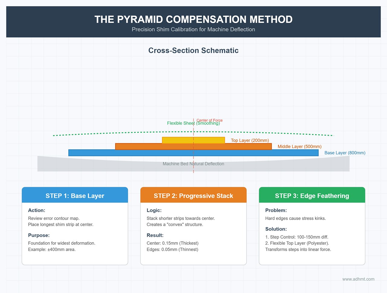
The goal of shim calibration is to physically build a “convex” structure that counteracts the machine’s natural deflection curve. This structure should not be a single flat layer but a pyramid-like formation—thicker in the center and thinner toward both ends.
| Step | Action / Procedure | Purpose / Design Logic |
|---|---|---|
| Step 1: Construct the Base Layer | Review the “error contour map” to identify deviations. Cut the longest shim strip (e.g., covering the central ±400 mm area, thickness 0.05 mm) and place it at the center of the bed. | Purpose: Serves as the foundation of the pyramid, addressing the widest zone of micro-deformation. |
| Step 2: Progressive Layering | Stack shorter shim strips on top of the first layer, gradually concentrating toward the center. Example Structure: • Bottom: Length 800 mm (0.05 mm) • Middle: Length 500 mm (0.05 mm) • Top: Length 200 mm (0.05 mm) | Physical Result: Reproduces a smooth, curved profile. Total thickness tapers from the center (0.15 mm) to midsections (0.10 mm) and outer edges (0.05 mm). |
| Step 3: Edge Feathering and Smooth Transition | Step Control: Maintain ~100–150 mm length difference between each shim layer. Flexible Top Layer: Cover the pyramid with a full-length sheet of high-quality 0.05 mm polyester film or dense kraft paper. | Purpose: Prevents steep steps, visible “kinks,” or angle jumps. The compressibility of non-metal materials fills micro-gaps, transforming stepped pressure into smooth linear force. |
3.3 Dynamic Verification and Closed-Loop Locking
Laying down the shims doesn’t mark the end of the process—the way you lock the die and verify the outcome determines ultimate success.
- Torque Management: Avoid the “Toothpaste Effect” When tightening the screws on the lower die holder, never proceed sequentially from one end to the other. Doing so pushes the shim’s slight bulge toward one side, ruining the compensation.
- Correct Sequence (Center-Out): Begin tightening from the machine’s center and alternate toward both ends.
- Two-Stage Tightening: First apply 50% of torque to pre-seat the die holder and shims without distortion; after verifying alignment, apply full torque to lock securely.
- Secondary Test Bend and Data Feedback Loop Perform another air bend using a full-length test piece—the results will reveal the truth.
- Interpreting Results: If the center angle shifts from 92° (under-bent) to 90°, congratulations—your calibration is perfect. If it’s 89° (over-bent), the shim stack is too thick.
- No Compromise: If over-bending occurs, remove one shim layer. Never attempt to fix it by reducing ram depth (Y-axis value). Lowering the depth might restore the center angle, but the ends—previously correct—will become under-bent (>90°), bringing the problem full circle.
- Digital Fingerprint Record (Documentation) Once you achieve the perfect shim configuration, that data becomes the machine’s unique “fingerprint.”
- Record Everything: Don’t rely on memory. Log the number of shim layers, their lengths, materials, thicknesses, and positions in the maintenance file (e.g., “Center +0.15 mm / 3 layers, each reduced by 150 mm”). When dismantling the die holder for major servicing, you’ll be able to restore hours of tuning in minutes. For guidance on maintaining and documenting press brake configurations, contact us or explore ADH Machine Tool for professional resources.
IV. Advanced Enhancement Module: Complex Scenarios and Expert Techniques
By mastering the Pyramid Compensation Method, you’re already ahead of 80% of operators. Yet true bending masters handle not just standard parts but also complex mixed conditions and extreme requirements. This module unveils the “invisible tactics” usually shared only among elite tooling engineers.
4.1 Hybrid Compensation Strategy
Modern high-end press brakes are typically equipped with hydraulic or mechanical CNC crowning systems. Many assume this makes shimming obsolete—a misconception. CNC crowning excels at adjusting macro trends, while shims address micro irregularities. The two are complementary, not interchangeable.
- Shim + CNC Crowning: The Perfect Duet
- Task Allocation: The CNC system handles the overall elastic deformation caused by bending pressure—essentially the large-scale, smooth U-shaped curve—covering about 95% of the compensation. Shims, on the other hand, correct localized die wear, machine asymmetry, or material thickness variation (since CNC systems generally only perform symmetrical, center-based compensation).
- Spot Correction:
- Scenario: The CNC crowning is active, and after a test bend, the center angle is perfect, but one specific spot on either side shows a 0.5° deviation.
- What Not to Do: Absolutely do not modify the global CNC parameters—doing so would disrupt the balance of the entire deflection curve.
- Correct Approach: Keep the CNC parameters unchanged. Insert a 0.05 mm shim precisely under the area showing deviation. This kind of “surgical precision” preserves the benefits of automated compensation while eliminating local imperfections.
- Differential Shimming Technique
- This advanced technique leverages the difference in compression modulus between materials to achieve submicron-level fine tuning.
- Physical Principle: Steel shims are nearly incompressible under load, whereas polyester film or high-density kraft paper can compress by approximately 5–10% under high pressure.
- Practical Application: Suppose you need 0.02 mm of compensation but only have a 0.05 mm shim available. Use a 0.05 mm polyester sheet—it will compress under full load to about 0.04–0.045 mm. Moreover, the soft shim’s edge deformation creates a smoother transition, making it an excellent method for preventing surface creases on precision parts.
4.2 Special Handling for Segmented Dies and Irregular Workpieces

Standard long, straight bends are just the basics—the real challenge lies in handling worn segmented dies and geometrically complex bends that defy mechanical intuition.
- Individual Segment Tuning
- Pain Point: When assembling long dies, one segment is often worn down (for example, 0.03 mm shorter than the new ones), causing that area to overbend.
- Technique: Don’t raise the entire 3‑meter die base for one worn section. Simply attach a 0.03 mm copper foil under the worn die segment and trim the edges neatly.
- Management Loop: After adjustment, permanently mark that die segment with a red paint pen and classify it as a “special compensated piece.” Never mix it back into the standard die set—doing so will create chaos during the next setup.
- Counterbalancing Off-Center Bending
- Challenge: When a workpiece must be bent along the far-left edge of the machine (due to a preformed flange or shape constraint), the ram tilts severely—producing a large outer angle and an undershot inner angle.
- Solution A (Preferred): Counterbalance with a Dummy Load. Place an identical-height, identical‑V “shadow die” and a scrap piece on the machine’s far-right (idle) side. Pressing both simultaneously balances hydraulic pressure and eliminates ram tilt at the source.
- Solution B (Compromise): Asymmetric Shim Stack. If a dummy load cannot be used, add extra shim thickness on the outermost side of the left die (the side farthest from the machine center). This is a “fight fire with fire” approach—using added height to counteract the ram’s outward opening tendency.
- Tapered Bending
- Special Requirement: The design specifies a tapered bend—90° at one end and 92° at the other.
- Shim Gradient Method: Build an artificial slope using shims.
- Formula: H = L × tan(Δα), where H is the height difference between shims at both ends, and L is the workpiece length.
- Critical Warning: This setup generates significant lateral force. Always use a ball-nose punch or rotating die holder. Using a rigid die under these conditions is highly likely to cause cracking or catastrophic die failure.
4.3 Application of Digital Assistive Tools
Turning experience-based craftsmanship into data-driven processes is a crucial step toward Industry 4.0.
- Laser Angle Feedback and Database Building
- Use laser angle measurement systems such as Data M or WILA to record changes in readings before and after shim adjustments.
- Create a Response Library: After several trials, build a machine-specific database—e.g., “With a V12 die, each additional 0.1 mm shim changes the laser reading by 0.8°.” When the same deviation reappears, consult the table to determine the correct shim thickness, turning trial‑and‑error into a quick lookup process.
- CAD/CAM Deflection Pre‑Calculation
- Software such as AutoPol, Radbend, or BySoft can simulate not only collisions but also deflection behavior.
- Predictive Insight: By entering your machine’s stiffness (tons per millimeter), the software can model the deflection curve under full load. For example, it might indicate: “At 500 mm from the center, expect 0.15 mm of deflection.” You can then pre‑arrange the appropriate shim set beneath the die. When the operator reaches the press brake with the drawing, the shim plan is already part of the process documentation—reducing setup time from an hour to just ten minutes.
V. Troubleshooting and Maintenance: Avoiding Pitfalls and Ensuring Long‑Term Precision

While shim adjustment can work wonders, it’s a double‑edged sword. Incorrect use not only fails to improve accuracy but may damage dies or even cause safety incidents. Once advanced techniques are mastered, true experts learn to recognize warning signs and establish a systematic management process to prevent accuracy drift over time.
5.1 Diagnosing the 5 Deadly Sins
Even seasoned operators with a decade of experience often stumble over the following five pitfalls. Review them carefully—any single oversight can lead to tens of thousands in die damage or serious injury.
- Over‑Compensation Trap (Reverse Deflection / Reverse Canoe)
- Symptom: The bent part shows an unusual profile—both ends open too wide while the center angle remains shallow, meaning the ends are over‑bent and the middle under‑bent.
- Pathology: This is the most dangerous warning sign. It indicates that the shim stack is excessively thick or that an incorrect calculation formula was used, causing the artificially created “crown” to exceed the machine’s natural deflection. As a result, several tons of pressure concentrate at the die’s center while both ends remain suspended.
- Consequence: The pressure at the die’s center can exceed three times its yield limit, making it highly susceptible to sudden rupture or explosion.
- Emergency Action: Upon detecting this symptom, immediately stop operation, remove all shims, inspect the die for hairline cracks, and recalculate everything from scratch.
- Stepping Effect and Surface Indentations (Stepping Effect)
- Symptom: Visible horizontal lines, indentations, or abrupt changes in surface gloss appear on the bent workpiece, corresponding to the edges of the shim layers.
- Pathology: The length gradient between shim layers is too short (for example, only 20 mm per step), or overly thick single-layer shims are used (such as stacking 0.2 mm foils directly). This causes discontinuous pressure transmission, creating “fault lines” at the base of the die set.
- Correction: Extend the transition zone of each shim layer (recommended >100 mm), or place a continuous 0.05 mm polyester sheet on top of the “pyramid” to smooth out the hard steps into a gentle slope.
- Bridging
- Symptom: The bending angle fluctuates severely, and the press emits an unusual metallic grinding sound during operation.
- Pathology: The shim used is narrower than the contact surface (shoulder) of the die base. The die base effectively “bridges” over the narrow shim, leaving its edges unsupported. This causes slight lateral rolling of the base under load.
- Iron Rule: The shim width must be equal to or greater than the effective contact surface of the die base to ensure full support and eliminate mechanical weak points.
- Phantom Drift
- Symptom: Even though the machine was calibrated in the morning, the bend angle drifts after producing a few hundred parts—or accuracy completely disappears after restarting the next day.
- Pathology: Caused by oil-absorbing paper shims or non-industrial-grade plastics.
- Oil Absorption and Softening: Paper shims absorb hydraulic oil or coolant, breaking down their fiber structure and compressing in thickness.
- Thermal Creep: Ordinary plastics deform under heat; as the hydraulic system warms up, the shims plastically flow and become thinner.
- Countermeasure: Eliminate all non-standard materials. Use only oil-resistant, high-temperature, anti-creep brass or stainless-steel shims.
- Safety Neglect
- Risk: Attempting a “test press” before reaching the specified torque, often out of convenience.
- Consequence: A die that is not fully locked can shift under rebound force—or even eject like a projectile—causing potentially fatal injuries.
- Standard Procedure: After any shim adjustment, even adding just a single 0.05 mm sheet, always verify that all bolts are torqued to specification using a torque wrench before pressing the foot pedal again.
5.2 Shim Management System

Don’t let shims become greasy, forgotten “orphans” in a workshop corner. A shop’s level of technical discipline is often reflected in how it treats these tiny metal sheets.
- Visual Inventory and Color Coding
- Distinguishing 0.05 mm from 0.08 mm by touch alone is unreliable. A clear visual management system is essential.
- Procurement Tip: Purchase industrial-grade shims with preset color codes (e.g., blue = 0.05 mm, yellow = 0.10 mm, red = 0.20 mm).
- In-House Solution: When using foil rolls, mark the corners with the corresponding color immediately after cutting. Never store offcuts of different thicknesses in the same box.
- Lifecycle Management
- Shims are consumables, not permanent assets. Even hardened spring steel fatigues or slightly flattens after tens of thousands of high-tonnage cycles.
- Policy: Conduct a quarterly “shim inspection.” Use a micrometer to sample-check permanent shims—especially the main central ones under the heaviest load. If thickness reduction exceeds 0.01 mm or any cracks or dents are found, immediately scrap and replace them.
- SOP Documentation of Process Assets
- Once a perfect shim configuration has been fine-tuned for a complex part, that setup becomes valuable process knowledge. Don’t let it remain only in a senior technician’s memory.
- Archiving Standard: For repeat orders, create a dedicated “Shim Map.”
- Photographic Record: Clearly show shim placement on the worktable.
- Data Annotation: Record detailed information including “layer count, each layer’s length, material, thickness, and starting coordinates.”
- Value: When the same order is produced again, even a novice can reproduce the setup by following the documentation—reducing setup time from two hours to fifteen minutes while maintaining identical precision.


