I. Core Cognitive Module: Redefining the Value of Bending Tools
1.1 Conceptual Reconstruction: More Than Just Cold Metal
In traditional workshop management, bending dies are often classified as simple "consumables"—a perception that comes at a high cost. For shops embracing modern automation, integrating advanced systems such as a CNC Press Brake can redefine this perception by turning bending into a data-driven precision process.
Anatomical Analysis: The “Iron Triangle” of Precision Manufacturing
To truly understand a die, one must uncover the hidden logic behind its three core components:
Upper Die (Punch) — The “Inner Radius Definer” and Source of Misconception
Explicit Function: Transfers pressure to force the sheet metal to deform.
Hidden Logic: A common misconception in the industry is that the punch tip radius (Rp) determines the inner radius of the workpiece. In fact, for air bending, which covers roughly 90% of applications, the natural inner radius (Ir) of the part is primarily defined by the V-opening width (V) of the lower die.
Insider Rule: For mild steel, an empirical formula applies—Ir ≈ V × 0.16. Only when the punch tip radius exceeds this natural value does it enforce a specific shape; otherwise, the punch merely acts as a pressure point, and the material itself forms naturally in the “air” through mechanics.
Lower Die (Die) — The “Reference for Geometric Tolerance”
The lower die is not just a support—it serves as the absolute reference surface for forming. The shoulder radius and V-angle precision directly determine the stability of bending angles and the depth of surface indentations.
Hardness Threshold: High-quality modern dies are treated by induction hardening or laser hardening, reaching a hardness of 55–60 HRC with a hardened layer depth of 3–4 mm. This resists wear from tens of thousands of high-pressure cycles. Below this standard, die accuracy deteriorates exponentially with use.
Clamping System — The “Neural Center”
This is the connection point between the machine and the die—and the area most prone to accuracy loss.
Technological Evolution: Traditional mechanical clamping plates easily cause slight die tilting due to uneven tightening force. Modern hydraulic clamping or Wila New Standard systems feature a self-seating mechanism that automatically eliminates micron-level gaps upon clamping—a physical foundation for consistent angles along the entire length.
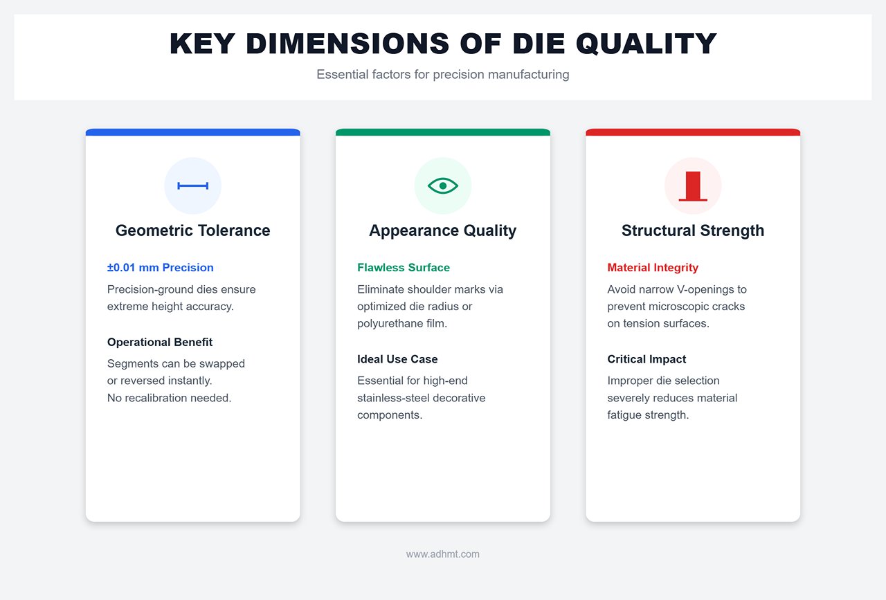
Three Dimensions Defining Die Quality
Geometric Tolerance: Precision-ground dies can achieve height tolerances within ±0.01 mm. This allows segments to be interchanged or reversed freely without recalibration.
Appearance Quality: By optimizing the lower die shoulder radius or using polyurethane protective film, shoulder marks can be eliminated—critical for stainless-steel decorative components.
Structural Strength: Choosing the wrong die (e.g., too narrow V-opening) can create microscopic cracks on the outer tension surface of the material, severely reducing fatigue strength.
1.2 Process Evolution: From “Empiricism” to “Data-Driven” Manufacturing
The evolution of bending technology is essentially the story of advancing die precision and digital integration. If your workshop still relies on veterans “feeling” their way through leveling with paper shims, you’re standing at the edge of obsolescence.
The Technological Divide: Planed vs. Precision Ground
This is the most striking technological gap in the bending field, with fundamental differences in physical properties:
Dimension
Traditional Planed Dies
Modern Precision Ground Dies
Manufacturing Process
Cut on a planer, typically in full lengths (3–6 m)
Ground on precision machines, produced in segments (e.g., 835 mm)
Reference Logic
Based on X-Y axes, limited by machine guideway accuracy
High cumulative error over length, about ±0.04 mm/ft
±0.01 mm, with zero cumulative error across full length
Interchangeability
Poor—dies must be assembled in factory-number order, not reversible
Excellent—segments can be freely interchanged, reversed, or replaced
Paradigm Shift in Processing: From Art to Part
Old Model (Empirical): Relied heavily on operator skill. With planed dies varying in precision, every tool change required lengthy alignment, trial bends, and compensation—a “manually governed” process that was slow and non-repeatable.
New Model (Data-Driven): Powered by Digital Twin technology. The precise dimensional data of ground dies can be directly integrated into the CNC system database.
The Truth About the K-Factor: The K-factor (neutral axis shift coefficient) depends not only on material properties but also on die geometry. Accurate dies enable CAM software to precisely predict the movement of the neutral layer, generating perfect flat patterns.
Ultimate Goal: Achieve “First Part Good” production—no trial runs or adjustments. Programs go straight to manufacturing, embodying the true value of bending dies in the Industry 4.0 era. For detailed technical references, you can download our brochures.
The Contest with Stamping: The Triumph of Flexible Manufacturing
In its competition with stamping, bending technology demonstrates unique economic logic:
Stamping Dies are specialized (hard tooling), with high mold costs—suitable only for million-piece production runs.
Bending Dies are universal (soft tooling). A single set of standard V-dies combined with CNC axes can produce thousands of part variations. With modern quick-clamping systems (tool change time < 2 minutes), bending perfectly fits today’s agile manufacturing model of “high mix, low volume.”
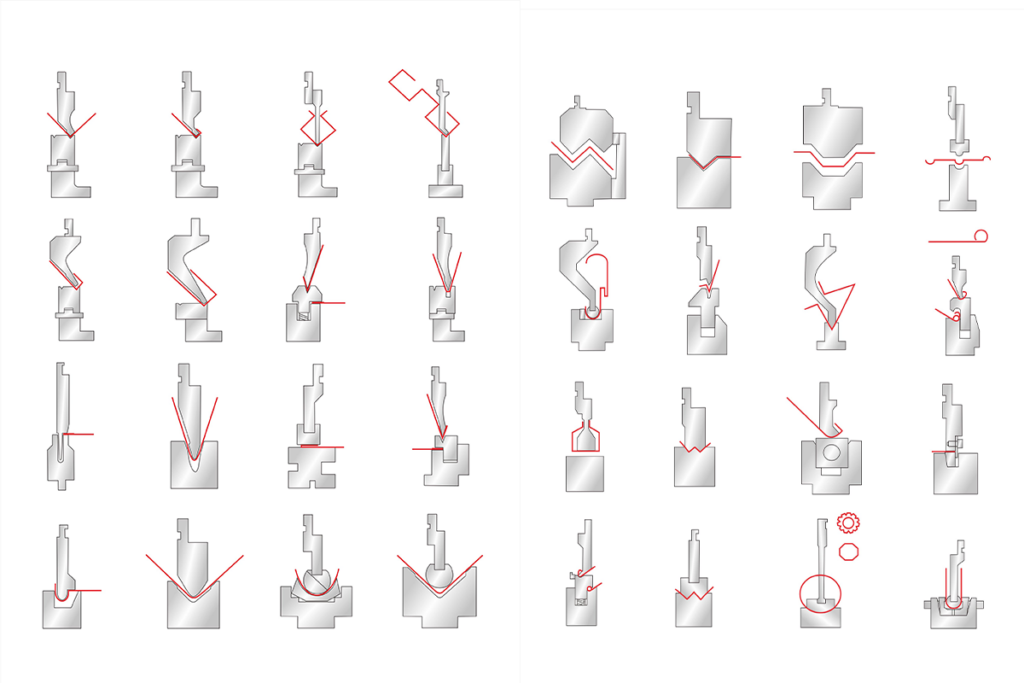
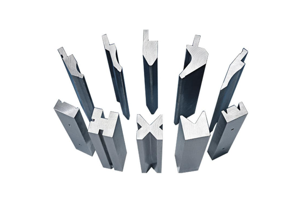
Ⅱ. Types of Press Brake Tooling
Punch
The punch is the upper tool in press brake tooling, mounted on the ram of the press brake. It exerts force on the workpiece, causing it to bend according to the punch's shape. Punches come in various designs to accommodate different sheet metal bending requirements and material types.
Standard Punches
Standard punches feature thick bodies and narrow tips, which are versatile and commonly used for general bending tasks, and high-tonnage applications. They are suitable for creating standard bends, such as 90-degree angles, in a range of materials. For instance, a standard punch might be used to create right-angle bends in mild steel sheets, ensuring consistent results across multiple pieces.
Acute Angle Punch
Acute angle punch is used for angles between 30-60 degrees and features a bulky body with a sharp tip. It is commonly used for bends less than 30 degrees, and can handle angles up to 89 degrees. Angle of the punch tip typically ranges from 28° to 34°.
Typical Dimensions
Clean-up width: Ranges from 1" to 1.5"
Working height: Usually around 3.75"
Tip radius: Varies from 1/32" to 1/8"
Goose Neck Punches
Gooseneck punches have a recessed profile that allows for intricate bends without interfering with the workpiece. These punches are specifically designed for U-profiles, perfect for deep box shapes and other complex forms. Gooseneck punch has an extended body with a concave area, which can prevent workpiece leg collision. For example, when creating deep U-shaped channels in a metal sheet, a gooseneck punch provides the necessary clearance to avoid damaging the material.
Sash Punch
Sash punch features a narrow body with an angled tip, and allows for bending and working around corners. The tip is bent towards the inside of the press brake. It allows angles on both sides of the bend, commonly used for making door jambs and sashes, and enables efficient processing of metal sheets for window frame fabrication.
Narrow/Sword Punch
Uniform thickness throughout length, narrow punch features straight, non-angled tip geometry, which are used in tight clearance situations, and ideal for final bends in box closing, suitable for limited space operations.
Radius Top Punch
Radius top punch is designed to create rounded bends due to its rounded tip instead of sharp edges, can work with standard V-dies, is used in marking operations, and creates smooth curved profiles. Typically has a thicker body to withstand the required bending forces.
Joggle Punch (Z-tool)
Joggle punch features a specialized shape for creating offset bends, is used for specialized applications, produces S-shaped profiles. It is a special tool and typically used for specific custom work and designed to make two bends simultaneously. It has a thinner profile compared to standard punches.
Die
The die is the lower tool in press brake tooling, mounted on the bed of the press brake. It provides the counterforce necessary to shape the metal as the punch presses down. Dies come in various shapes and sizes to create different types of bends.
V Dies
V shaped die is the most common type of die, available in single V, double V, and multi-V types, which feature a shaped groove. It is used to create v-shape bending for the workpiece. The width and depth of the v groove determine the final bending angle and radium. It can be part of a four-way die block for easy changeovers. Learn more about compatible press brake systems in our CNC Press Brake solutions.
U Dies
'U' dies are used for creating channels and deeper bends, ideal for operations requiring more complex shapes. Designed specifically for creating U-shaped or C-shaped bends, they can produce bends ranging from 90° to 180°. An example is forming deep channels in a metal sheet for structural components, where a 'U' die ensures uniformity and strength.
Flattening Dies
Flattening dies are used to flatten the bent material, ensuring a smooth and polished finish. These dies are essential for achieving a professional appearance in the final product, such as in the production of flat metal panels for automotive body parts.
Offset Dies
Offset dies are used to create Z-shaped or offset bends, and produce two angles in one stroke. They increase accuracy by keeping bends parallel.
Radius Dies
Radius dies are used with rounded punches to form radiused bends, which can create smooth, curved profiles.
Gooseneck Dies
The gooseneck die is designed to avoid workpiece interference, allows for bending in tight spaces or around existing bends. It is mainly designed for removing protruding edges or flanges on workpieces, making them the ideal choice for bending profiles with deep boxes or high flanges.
Hemming Dies
Hemming dies are used for creating hems or folded edges, which can improve aesthetics and strengthens edges of sheet metal components. they transform the flat edges of the workpiece into circular and seaming shapes for finishing
Channel Forming Dies
Channel forming dies create U-shaped channels in a single pass, they are more efficient than using traditional V-dies for U-shapes.
Flattening Dies
Flatting dies are used to completely flatten acute angle bends, often used in conjunction with hemming operations.
Four-way Dies
Four way dies feature different V-die sizes on each side of a single block, allows for quick changeovers without retooling.
Multiple Bend Dies
Multiple bend dies are designed to create two or more bends in a single operation, including specialized types like offset dies.
Ⅲ. Systems and Classification: Understanding the Underlying Logic of the Die World
In the realm of press brake tooling, standards represent more than dimensional differences—they reflect competing philosophies of precision transmission. Choosing a tooling system is, in essence, choosing your factory’s future production model and competitive edge.
3.1 The Deep Rivalry Among Three Main Global Standards
The global bending industry is dominated by three distinct die standards, each embodying a unique industrial mindset.
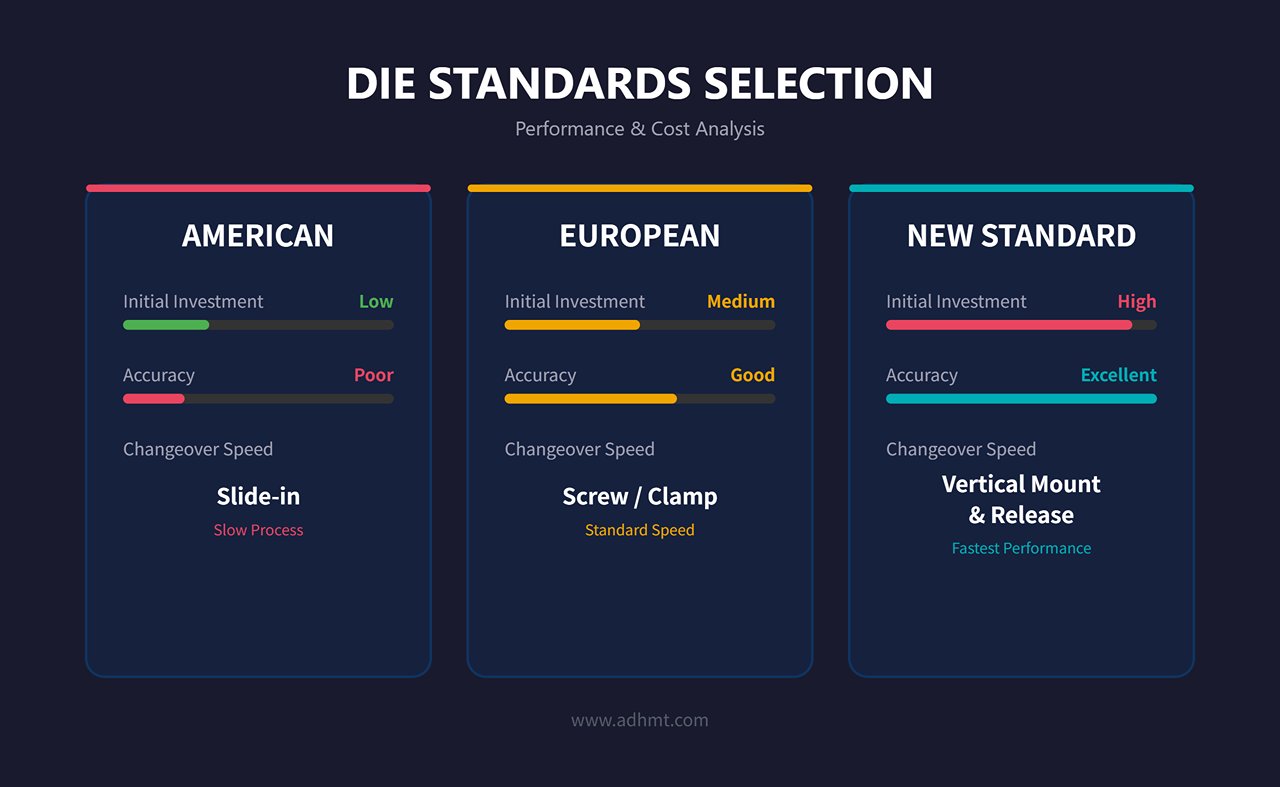
1. American Style: A Compromise Between Economy and Rough Precision
This is the most traditional die format, characterized by a simple flat-head design.
Core Pain Point: The biggest drawback of the American-style die lies in its accuracy degradation. Since it relies on the flat top surface for load-bearing and side screws for clamping, frequent installation and removal over time lead to wear on the clamping surfaces, causing subtle “tilting” when the die is under force.
Operational Bottleneck: It lacks a “Safety Click” mechanism, meaning the die must be slid in and out from the side of the machine during changeovers. On a 3-meter press brake, this results in significant time loss and safety hazards.
Ideal Applications: Best suited for rough, low-cost production or factories where die changes are infrequent. However, it has steadily fallen out of favor in precision sheet metal manufacturing.
2. European/Promecam Style: The All-Rounder of Precision Manufacturing
Currently the most widely used global standard, easily recognized by its 13 mm offset tang design.
Design Logic: The asymmetrical structure isn’t for aesthetics—it’s engineered to provide extra clearance for complex part bending. Its greatest advantage is versatility: whether you’re operating an Amada, Trumpf, or most domestic machines, European-style tooling is almost universally compatible.
Ideal Applications: The go-to choice for precision sheet metal workshops, especially in environments with diverse product types and small to medium batch sizes.
3. New Standard (Wila/Trumpf): The Crown of Automation
This represents the pinnacle of die technology, featuring a 20 mm wide tang typically used with hydraulic clamping systems.
Technical Edge – Self-Seating: This is its defining innovation. When hydraulic pressure is applied, the locking pins not only secure the die but also generate an upward pulling force that firmly seats the die against the reference surface. This eliminates installation gaps and achieves a form of “living precision alignment.”
Efficiency Revolution: With the press of a button, dies can be mounted or removed vertically from the front—known as vertical loading—making changeovers 5–10 times faster than with American-style systems.
Ideal Applications: Perfect for automated bending cells (robotic systems) and high-end production requiring extreme precision (within ±0.1 mm tolerance).
[Decision Reference] Matrix for Selecting Mainstream Die Standards Initial Investment: American (Low) < European (Medium) < New Standard (High) Long-Term Accuracy: American (Poor) < European (Good) < New Standard (Excellent) Changeover Speed: American (Slide-in) < European (Screw/Quick Clamp) < New Standard (Vertical Mount/Release)
3.2 Functional Classification Based on Bending Method
A common beginner’s mistake is confusing “tool geometry” with “bending method.” In reality, the same die can perform very differently under different processes.
Air Bending – The Art of Flexibility
This process dominates about 90% of modern bending applications.
Principle: A typical three-point contact system—between the punch tip and the two shoulders of the V-die. The workpiece never touches the bottom of the V.
Insider Insight: Air bending is the most tonnage-efficient method. By simply controlling the ram depth (Y-axis), you can produce any angle from 90° to 180° using the same set of dies.
Key Trade-off: Springback. To offset the metal’s elastic recovery, standard European dies are typically made at 88° or 85°—those extra degrees act as built-in compensation for springback.
Bottom Bending – The Misunderstood Precision Method
Principle: The sheet is pressed until it fully contacts the sidewalls of the V-die.
Key Difference: Many assume this is “coining,” but it isn’t. Bottom bending requires roughly 1.5–2 times the tonnage of air bending. Its benefit lies in higher accuracy and minimal springback, but the drawback is rigidity—the bending angle is fixed by the die. A 90° die can only produce a 90° bend, offering limited flexibility.
Hemming – The Hidden Tonnage Trap
This high-risk process can easily damage machines if mishandled. It typically involves two steps: first forming a sharp bend (around 30°), then flattening it.
Risk Alert: The flattening stage demands enormous force. For example, 1 mm cold-rolled steel requires about 40–50 tons of pressure per meter. If operators apply parameters suited for air bending, the result can range from incomplete hemming to permanent deformation of the machine frame. Modern setups often use specialized spring-loaded hemming dies to absorb the shock load.
3.3 Material Science and Manufacturing Craftsmanship – The Overlooked Essentials
Many factories focus solely on price, overlooking the metallurgical structure within the die steel. This is often why a “cheap to buy, costly to use” situation arises.
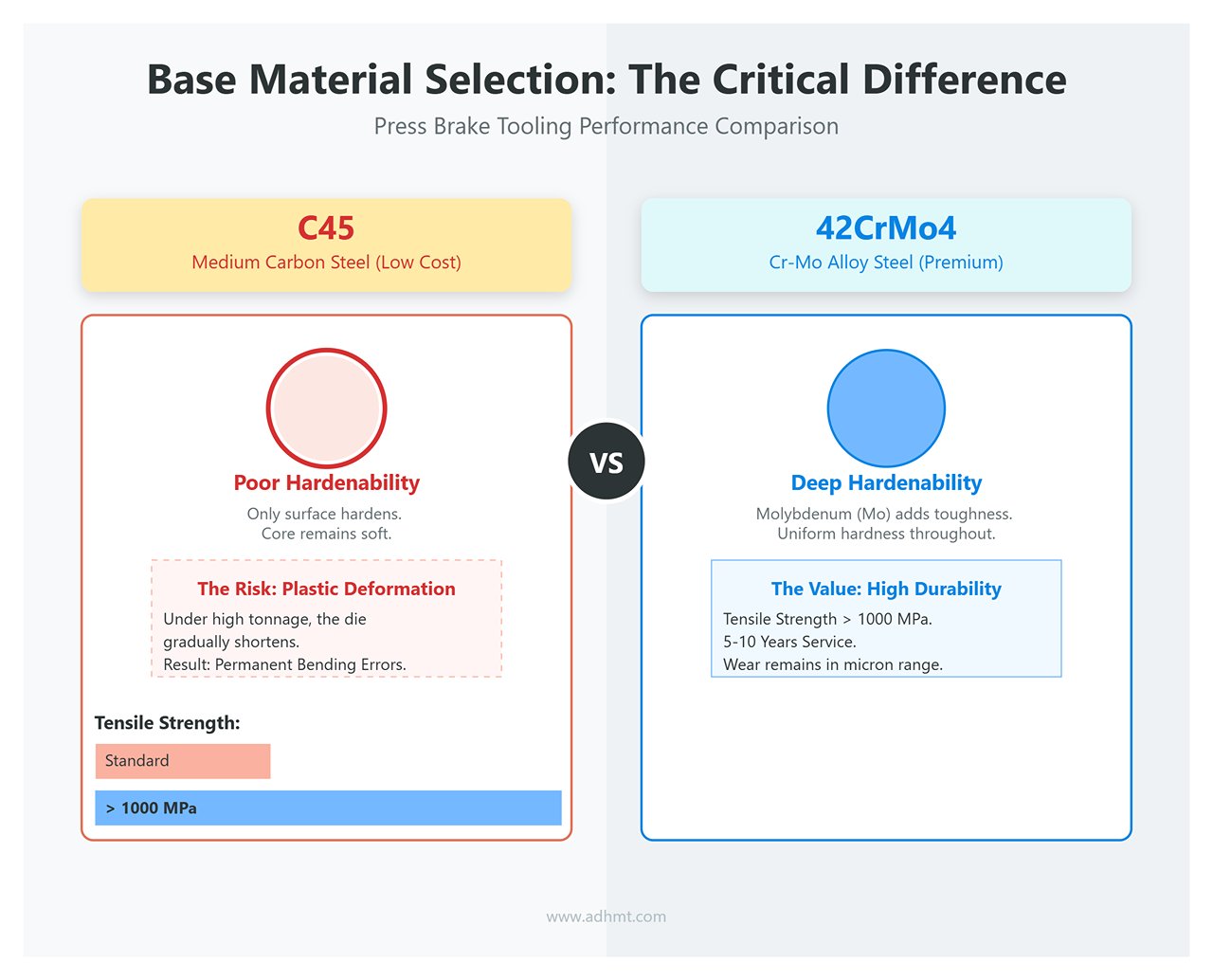
Base Material Selection: 42CrMo4 vs. C45
C45 (Medium Carbon Steel): Commonly used in low-cost dies. Its fatal weakness is poor hardenability—only the surface hardens after heat treatment, while the core remains soft. Under prolonged high-tonnage loads, C45 dies are prone to plastic deformation (gradually shortening), leading to permanent bending angle deviations that cannot be corrected.
42CrMo4 (Chromium-Molybdenum Alloy Steel): The hallmark of premium dies. The molybdenum (Mo) component provides excellent toughness and deep hardenability. With tensile strength exceeding 1000 MPa, it ensures that even after 5–10 years of service, wear remains within the micron range.
Heat Treatment Technology: Balancing Hardness and Toughness
If a die is too hard, it becomes brittle like glass and shatters on impact; if too soft, it wears quickly. The optimal solution is laser hardening.
Precision Engineering: Laser beams selectively heat only the stressed zones (the punch tip radius and V-die shoulders) with a controlled depth of 0.5–1.5 mm, achieving surface hardness above HRC 60 almost instantly.
Value Proposition: This method preserves 95% of the die’s core toughness, creating an ideal “iron core with a steel skin” structure—resistant to both wear and impact without cracking.
Ⅳ. Practical Selection Strategies: Golden Rules and Pitfall Avoidance
Choosing the right die is not a matter of visual matching—it’s a precise calculation rooted in material mechanics and geometric interference. A wrong choice can skyrocket scrap rates or even cause die breakage and machine damage. This chapter provides a standardized, actionable SOP to help you move from intuition-driven decisions to data-based precision.
4.1 Pre-Selection Parameter Audit: Six-Dimensional Data Review
Before consulting any die catalog, conduct a thorough data audit. Missing any of the following parameters means you’re essentially making a blind choice:
Sheet Material (Material): Determines the material’s ultimate tensile strength (UTS). Stainless steel exhibits far greater springback and requires higher tonnage than mild steel, which directly affects V-die selection and angle compensation strategy.
Sheet Thickness (T): The foundation of all calculations—it dictates the width of the lower die’s V-opening.
Target Angle: It’s not just the 90° or 135° shown on the drawing. You must anticipate springback characteristics to choose the correct punch angle (for example, selecting 88° instead of 90°).
Inside Radius (IR): Does the client specify a strict tolerance for the inner radius? If so, it will limit your flexibility in choosing the V-die width.
Minimum Flange (Min Flange): The most commonly overlooked “bottleneck” parameter. If the V-die is too wide, the short flange will slip into the die opening, making bending impossible.
Machine Capacity: The physical limit. Ensure that the required tonnage per meter stays within the machine’s safe operating load.
⚠️ Critical Pitfall: Interference Check — Don’t rely solely on the flat pattern drawing! You must predict dynamic interference throughout the bending process. When working on U-shaped parts, deep boxes, or pieces with reverse flanges, it’s common for part walls to collide with the tooling mid-bend. Use CAD cross-section simulations or simple cardboard mockups as low-cost, high-value preventive measures.
4.2 The Four-Step Method for Scientific Tool Selection (Core Methodology)
Following these four steps will solve about 90% of common bending tool selection challenges:
Step 1: Determining the V-Opening of the Lower Die
This is the first decision that defines bend quality. Don’t memorize formulas blindly—understand the underlying lever principle:
The Rule of 8: For mild steel, the standard formula is V = 8 × T (sheet thickness). This provides an optimal balance between required tonnage and bend quality.
Advanced Adjustment Strategies:
Aluminum/Soft Materials: Due to their higher ductility and lower cracking risk, use V = 6 × T to achieve a smaller inner radius.
Stainless Steel/High-Strength Steel: With higher strength and greater springback, use V = 10–12 × T. A larger V-opening significantly reduces required tonnage (protecting the tooling) and minimizes surface impressions, though it will increase the inner radius.
Step 2: Matching Punch Angle and Radius
Springback Compensation:
Never choose a punch angle identical to the target bend angle—air bending always involves overbending.
For 90° bends in stainless steel, expect 3°–5° of springback; therefore, use an 84° or 86° punch.
For 90° bends in mild steel, springback is about 1°–2°; an 88° punch is usually ideal.
Sharp Bend Risk:
If the punch tip radius (Rp) is too small (e.g., Rp < 0.63 × T), it can act like a blade when forming high-strength steel, causing cracks along the outer bend line. For aerospace aluminum or high-strength steels, choose a rounded punch with Rp ≈ T to distribute stress more evenly.
Step 3: Choosing the Tool Profile
Straight Punch: The most robust and economical option, suitable for flat parts and simple L-shaped bends.
Gooseneck Punch:
The go-to solution for “return bend interference.” Its recessed neck allows deep U-bends or hems without hitting the tool body.
Practical Warning: Because of the neck cavity, gooseneck punches are structurally weaker than straight punches—never exceed the rated tonnage, or they may fracture.
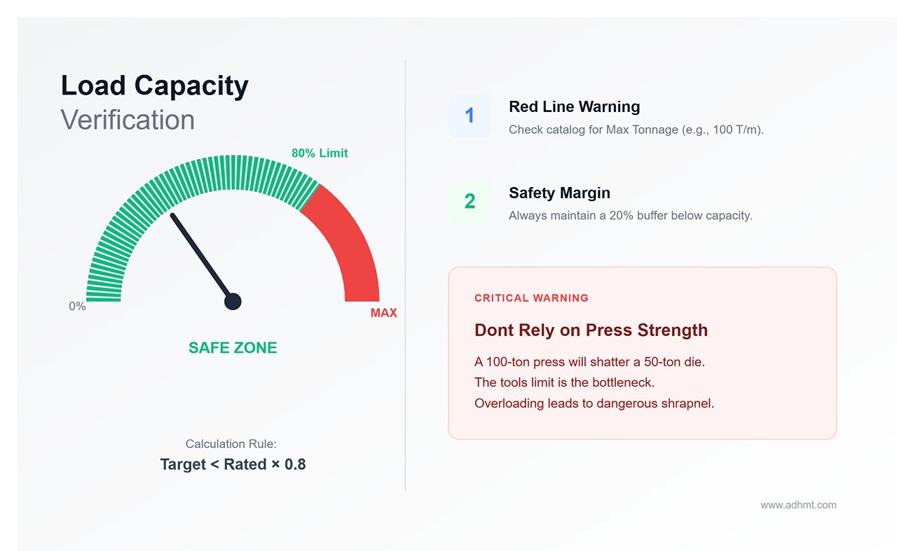
Red Line Warning: Every tool catalog lists a Max Tonnage (e.g., 100 T/m).
Calculation Rule: The actual required tonnage per meter must be < Rated Tool Capacity × 0.8 (keeping a 20% safety margin).
Fatal Misconception: Many operators assume that “as long as the press is strong enough, it’ll work.” Absolutely wrong! Even if the press delivers 100 tons of force, a die rated for only 50 tons can shatter violently, sending fragments flying like shrapnel.
4.3 Tool Length Combination Strategy
One-Piece vs. Segmented Tooling
Don’t just buy several 835 mm full-length tools. A well-equipped shop must maintain a standard segmented set (e.g., 10, 15, 20, 40, 50, 100, 200, 400 mm segments).
Practical Value – Box Bending: When bending a box with all four sides raised, the last two bends will inevitably interfere with the previously formed sides. Use segmented tools slightly shorter than the box’s inner width (leave 0.5–1 mm clearance on each side).
Ear/Horn Punch: The end segments of a set often include beveled “ear punches” that clear the flanges of box sides—essential for manufacturing electrical enclosures and chassis parts.
Recommended Standard Tool Library
For a mid-sized precision sheet metal workshop, the following starter configuration will cover around 80% of production needs:
2 sets of full-length straight punches (for most simple parts).
1 set of full-length gooseneck punches (for U-shaped and deep-channel parts).
1 set of standard segmented straight punches with ear punches (for box-shaped and custom-width parts).
1 set of 30° sharp-angle tools (for pre-hem operations or special angles).
This chapter goes beyond the basics—it focuses on advanced methods that give you an asymmetric edge in a fiercely competitive market. If the previous chapters answered “Can we bend it?”, this one addresses “Can we make money doing it?”
5.1 Surface Treatments and Coatings: The Invisible Force Behind Productivity
If your dies are still running “bare” (without any surface treatment), your production efficiency is already down by at least 30%. In modern machining, advanced coatings are no longer cosmetic “anti-rust makeup” — they’ve evolved into an engineered “exoskeleton” that transforms physical performance.
TiCN (Titanium Carbonitride) Coating — The Nemesis of Galvanized Steel
Pain Point: When processing galvanized sheet, the zinc layer tends to peel off under high pressure and adhere to the V-die shoulder, forming tough “galling” deposits. This not only causes severe scratching on subsequent parts but also forces operators to stop and polish the die every few hours — a massive drain on productivity.
Solution: TiCN coatings have a distinctive gray-blue color and a hardness of up to 3000 HV (around five times that of the substrate) with an extremely low friction coefficient. It essentially gives the die a “Teflon-like nonstick surface,” effectively preventing zinc adhesion and extending cleaning intervals from once a day to once a month — dramatically cutting downtime.
DLC (Diamond-Like Carbon) Coating — The Ultimate No-Marking Solution for Aluminum
Pain Point: Aluminum alloys are soft and prone to sticking, while decorative components demand flawless surface appearance. Even the slightest friction mark from the die can render a part defective.
Solution: DLC coatings provide exceptional smoothness with a friction coefficient below 0.1. They allow the die surface to glide over the sheet like silk, enabling genuine “dry lubrication.” This makes DLC the go-to solution for high-end aluminum panels and aerospace interior components.
Non-Metallic Alternatives — A Cost-Effective Soft Landing
For occasional scratch-free jobs, there’s no need for costly coated dies. Laying a urethane protective film over the lower die or using a specially designed composite lower die creates a physical barrier that prevents metal-to-metal contact. While not as durable, it’s an extremely cost-effective tactic for achieving “zero-scratch” results.
5.2 Quick Change Systems — The Alchemy of Time
In today’s manufacturing world of “high mix, low volume,” setup time is the black hole that devours profit. A machine generates no value while changing dies, so whoever shortens this downtime gains the power to dictate prices.
The Economics of Speed: Traditional manual die changes using bolts can take about 30 minutes on a 3-meter press brake. With hydraulic or mechanical quick-clamping systems (e.g., Wila/Trumpf designs), this process can be reduced to under 3 minutes. ROI Calculation: Assuming four die changes per day and an hourly machine rate of $100, the annual time savings are worth around $45,000. In most cases, the investment in a quick-change system pays for itself within six months — everything afterward is pure profit.
Safety Click & Vertical Loading: If you’re still struggling to slide long dies in and out from the side like threading a skewer, you’re not only wasting time but also risking serious injury. Modern dies equipped with Safety Click mechanisms have revolutionized handling through vertical loading. Operators can simply push the die upward into the clamp from the front of the machine; one crisp “click” locks it in place — no need to hold, no risk of it dropping on your foot. It’s not just an efficiency upgrade but a leap in ergonomics and safety, and a prerequisite for robotic bending automation.
5.3 Modularity and Station Layout — Stage Bending
This is the art of condensing an entire production line into a single press brake — the true mark of an advanced operator.
Process Logic: Traditionally, operators bend all parts for the first angle, stack them on a tray, then change tools for the next bend — creating large work-in-progress (WIP) inventories and excessive handling. Stage Bending eliminates this waste by installing three to four different die sets along the full machine length (e.g., Station 1: acute bend → Station 2: hemming → Station 3: large radius bend → Station 4: reverse bend). The operator processes a single sheet through all stations from left to right — finished in one continuous pass.
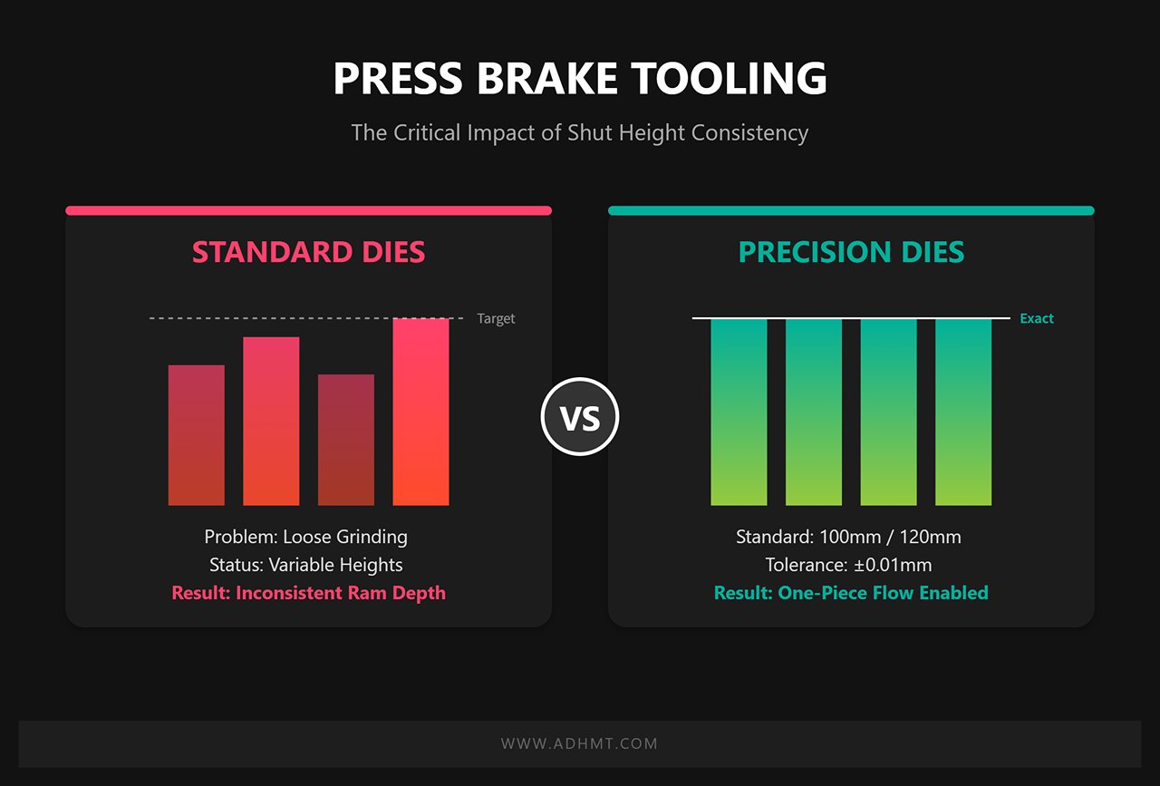
Critical Requirement: Common Shut Height: To make this process feasible, one physical challenge must be overcome — all punch types (straight, gooseneck, pointed) must share the exact same closed height.
Standard Dies: Due to loose grinding and tolerance control, die heights vary between batches, making it impossible to operate under a consistent ram depth.
Precision Dies: Premium European or new-standard dies are manufactured with unified closed heights (commonly 100mm or 120mm) and a tolerance of ±0.01mm. This gives the press brake exceptional flexibility, enabling true one-piece flow production.
Ⅵ. Maintenance and Management — Practical Guidelines for Extending Tool Life
In precision sheet metal fabrication, press brake dies are not mere consumables — they are critical assets that determine product yield. Adopting a full lifecycle management approach can extend die life by two to three times and eliminate hidden defects caused by gradual precision loss.
6.1 The “Three Essentials” of Daily Maintenance
Many expensive precision dies don’t fail from normal metal fatigue — they’re destroyed by dirt. In workshop environments, dust mixed with oil turns into an abrasive paste. Therefore, daily maintenance must strictly follow the three-step rule: Clean, Lube, Inspect.
1. Clean — The First Line of Defense for Accuracy
Key Action: Before every die change, thoroughly wipe the die clamping surfaces and the machine bed using a lint-free cloth.
Underlying Logic: Under tens of tons of hydraulic pressure, even a 0.1mm metal chip trapped between the die and the machine acts like a nail, embedding into the surface and causing permanent dents. This not only damages reference surfaces but can also tilt the die slightly during installation, creating uncorrectable angle deviations along the entire length.
Targeted Cleaning: When working with hot-rolled steel or materials with heavy mill scale, clean the inside of the V-die at least once per shift to prevent buildup that alters the effective depth of the V-groove.
2. Lube — The Principle of Moderation
Common Mistake: Many operators tend to smear grease all over the die — a serious error.
Proper Practice: Lubricants should be applied only to friction contact areas.
Lower Die Shoulder (V-Die Shoulder): This is where the sheet metal experiences the most intense sliding friction. Apply only a minimal amount of dry lubricant or specialized die oil to reduce wear and surface scratching.
Tang/Clamping Surface: Never apply heavy grease. Grease attracts dust and airborne particles, forming sludge that compromises die alignment and self-seating accuracy. This area must remain completely dry and clean.
3. Inspect — Prevent Problems Before They Occur
Visual Standard: Establish a routine for visual inspection at least once a week.
Key Focus Points: Pay special attention to the punch tip and the lower die shoulder. For precision dies with a tip radius of R0.6, if the tip wears to a small R1.0 or shows even slight chipping visible to the naked eye, stop using it immediately. Continuing to operate with a worn die can scratch the sheet surface and cause uneven stress distribution along the bend line, leading to complete loss of angle consistency.
6.2 Storage and Handling Guidelines
The risk of die damage during storage is often greater than during use. Disorganized storage is the silent killer of die precision.
Storage Environment: Why Use Enclosed Cabinets?
Shield Against “Industrial Smog”: Open shelving is disastrous for precision dies. Airborne oil mist and metal dust in the shop settle on die surfaces, forming stubborn sludge and trapping moisture that can trigger intergranular corrosion.
Ideal Setup: Use enclosed metal cabinets with drawer liners made from high-density EVA foam or polyurethane channels. These liners prevent contact between dies, while the enclosed space maintains optimal humidity between 40%–60%. Each die should be stored separately—like surgical instruments—without any stacking.
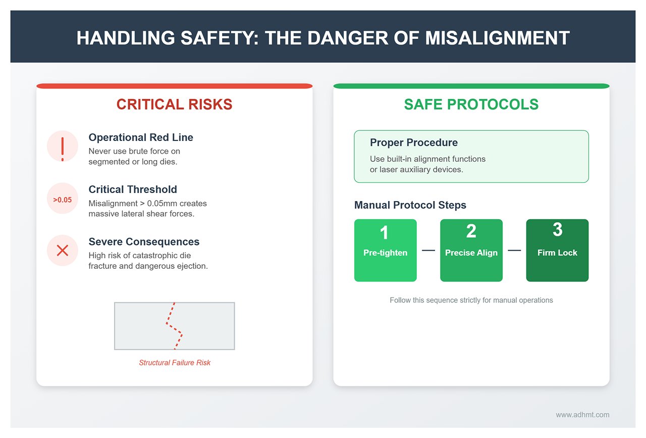
Handling Safety: The Danger of Misalignment
Operational Red Line: When installing segmented or long dies, never rely on brute force.
Physical Consequences: If the die centerline is misaligned with the machine centerline by more than 0.05mm, enormous lateral shear forces will occur at the moment of pressing, which can cause catastrophic die fracture and ejection.
Proper Procedure: Always use the machine’s built-in alignment function or a laser alignment device. For older machines without automatic clamping systems, follow the sequence: pre-tighten, align precisely, then lock firmly.
6.3 Service Life Management and Reconditioning
When should a die be scrapped or re-ground? This decision must be driven by data, not intuition. To ensure consistent results, schedule regular checks and consult professionals through our contact us page for reconditioning advice or OEM replacements.
Determining the Wear Threshold
Angle Deviation Rule: When performing a 90° bend, if the angle deviation along the full length exceeds ±1°, and compensation through the CNC Y-axis or deflection control can no longer correct it (usually because the V-opening has worn into an asymmetric oval), this is a clear signal that the die needs regrinding or replacement.
Hardening Layer Limit: For precision dies treated with laser or induction hardening (such as Wila or Trumpf types), the hardened layer is typically 3–4 mm deep. Once wear penetrates this layer and exposes the softer substrate, wear accelerates exponentially. At this stage, the die has no regrinding value and must be scrapped.
Regrinding Pitfalls: Avoid “Back-Alley” Services
Fatal Mistake: Many factories, aiming to cut costs, send dies to ordinary surface grinding shops for edge regrinding. The edges may appear sharp afterward—but the die is effectively ruined.
Root Cause — Shut Height: The essence of a precision die lies in its uniform height. Conventional regrinding removes material from the cutting edge, reducing overall height (for example, from 100 mm to 99.5 mm).
Disastrous Outcome: If this 0.5 mm shorter re-ground die is used alongside new OEM dies in the same press, the height difference will cause all the pressure to concentrate on the taller die. The result: the new die shatters instantly due to overload.
Correct Approach: Always use the original manufacturer or a qualified facility capable of matched grinding. They remove identical amounts of material from each die to maintain equal height across the set. After regrinding, the new height should be clearly re-marked, and operators must update the corresponding Z-axis/height parameter in the CNC system before resuming operation.
Ⅶ. FAQs
1. What are the main differences between precision-ground and non-precision-ground tooling?
Precision-ground tooling is manufactured with extremely tight tolerances, ensuring high accuracy and uniformity across the entire tooling set. This level of precision is essential for applications requiring exact angles and repeatability, as seen in industries like aerospace or medical device manufacturing.
Non-precision-ground tooling, while more affordable, has looser tolerances and is generally suited to less exacting applications. Choosing between these options depends on production requirements, with precision-ground tooling being preferable for high-accuracy tasks where consistency is critical.
2. How often should press brake tooling be calibrated?
The frequency of calibration depends on production volume, material types, and precision requirements. For high-precision applications or continuous production environments, calibration should be performed weekly or even daily, as this ensures consistent bending accuracy and minimizes potential deviations.
In less intensive operations, monthly or quarterly calibration may be sufficient. Establishing a regular calibration routine aligned with production demands helps maintain accuracy and reduces rework or waste.
3. What factors affect the lifespan of press brake toolings?
Several factors impact tooling lifespan, including material quality, usage intensity, workpiece material hardness, and maintenance practices. Press brake tooling is usually made from high-grade tool steels or treated with specialized coatings generally lasts longer, especially in high-volume environments.
Regular cleaning, lubrication, and inspections also significantly extend tooling life by preventing premature wear. Additionally, avoiding excessive tonnage and adhering to recommended operational guidelines protects tooling from undue stress and extends its usable lifespan.
4. Can press brake tooling be used for all types of metals?
While press brake tooling is versatile, different metals require specific tool characteristics to ensure optimal performance. For instance, harder metals like stainless steel or titanium exert more force on tooling, making high-strength or carbide-coated tools ideal for these applications.
Softer metals, like aluminum, require less robust tooling but benefit from softer dies or punches to prevent surface marring. Matching the tooling to the material type optimizes both tool longevity and the quality of bends, enhancing the overall efficiency of the press brake operation.
5. How do I make the right press brake tool selection for my project?
First, consider the material characteristics, including type, tensile strength, and yield strength, as these will dictate specific tooling needs. Different materials like aluminum, carbon steel, and stainless steel have unique properties that require distinct adjustments.
Next, assess the material thickness and length. The die opening should generally be 8 times the material thickness. The length of the material will determine the tooling length required. The bending angle and shape are crucial. Specific bend shapes, such as V-bends or hems, need corresponding tools. Understanding the desired bend will guide you in choosing the right tooling.
Tool profile and load limits are also vital. Match the tool profile to the job type—whether air bending, bottom bending, or coining—ensuring the load limit doesn't exceed the press brake's capacity to avoid damage.
Die selection should align with the metal thicknesses involved. Use the "8×2 rule" to find the smallest V die needed by multiplying the thinnest metal by eight. Adjustable dies are useful for projects with multiple bends.
For punch selection, choose based on job requirements. Consider punch types like Standard, Goose Neck, or Acute Angle, and ensure the nose radius fits the air-forming radius value.
Precision and compatibility are important for achieving part accuracy. Opt for tools with high precision and features like segmented sections and self-retaining installation for ease and safety. Consider tooling options and customization. While standard tools suit common bends, custom tooling may be needed for unique specifications, enhancing forming efficiency.
Finally, focus on setup and operation. Tools that allow front loading can reduce setup times. For projects needing frequent tool changes, having dedicated tool libraries for each press brake machine can improve efficiency. For further consultation or custom tooling requests, please contact us.
Explore More: Download our latest brochures to access detailed specifications and performance data for CNC and NC press brake solutions.
Not sure which machine is right for your sheet metal product? Let our knowledgeable sales team guide you in selecting the most suitable solution for your needs.