Press brake aluminum bending is a discipline of precision, not just force. This definitive guide moves beyond common workshop rules, offering a deep dive into material science, advanced process control, and expert troubleshooting.
It provides a complete engineering framework to eliminate costly cracking, unpredictable springback, and surface defects, transforming your results from scrap to perfection.
I. Rethinking the Fundamentals: Why Aluminum Bending Follows a Different Logic Than Steel
Most sheet metal professionals build their experience around carbon steel. However, if you try to apply the same “muscle memory” from steel bending directly to aluminum, the outcome is often disastrous.
Aluminum isn’t just a “softer metal”—its unique crystal structure and physical properties require an entirely different approach to forming. To understand how to adapt your press brake setup, you can explore more insights on press brake aluminum bending.
1.1 Core Differences: Breaking the “Soft Means Easy to Bend” Illusion
A common rookie mistake is assuming that because aluminum is softer than steel, it must be easier to bend. This is a dangerously misleading assumption.
- The Ductility Paradox – The yield strength of 6061‑T6 aluminum alloy is about 270 MPa, indeed lower than many high‑strength steels, but its fracture toughness is extremely low. The “T6” temper means the alloy has been solution‑heat‑treated and artificially aged, forming fine strengthening precipitates along grain boundaries. These precipitates act like nails that pin dislocations, increasing strength but drastically reducing ductility. Practical effect: Steel typically shows visible necking before fracture, giving you a warning; hard‑tempered aluminum alloys (like 6061‑T6 or 7075) often fail suddenly with brittle, intergranular cracks. When bending aluminum, you’re walking a tightrope at the material’s physical limit. Learn more about the mechanical behavior of aluminum under press brake forming in press brake aluminum bending.
- The Modulus Trap – Springback isn’t governed solely by hardness; it depends on the ratio of yield strength to elastic modulus. Aluminum’s modulus is about 70 GPa—roughly one‑third that of steel (~210 GPa). Practical effect: Under the same elastoplastic deformation, aluminum stores three times more elastic recovery energy than steel. When aiming for a 90‑degree angle, steel might only need to be over‑bent to 92°, while some aluminum alloys may require 94° or more to compensate for springback. This nonlinear behavior often renders traditional bending formulas unreliable.
- Surface Sensitivity: The “Eggshell Effect” of Aluminum Oxide – Aluminum naturally forms a very thin but extremely hard oxide layer with ceramic‑like properties, while the underlying metal remains soft. Practical effect: During bending, this hard skin slides against the die surface. Once the oxide film fractures, it can embed itself into the steel die surface, causing severe galling. Aluminum debris stuck on the V‑die acts like sandpaper, instantly ruining the surface finish of subsequent parts.
1.2 Common Pain Points and Hidden Cost Traps
In aluminum fabrication shops, most scrap parts end up there for three recurring reasons:
- The Invisible Killer: Micro‑Cracking – The most dangerous defects are often invisible to the naked eye. Parts that appear flawless may reveal thin red lines along the bend during dye‑penetrant inspection, indicating ductile tearing within the material. These micro‑cracks may hold under static conditions but will rapidly propagate under vibration, leading to catastrophic failure. Warning: For aerospace or load‑bearing components, micro‑cracks are an automatic rejection criterion.
- Surface Defects: The “Orange Peel Effect” – When you notice a rough, dimpled texture resembling orange skin along the outer bend, the culprit is usually not a dirty die but the material itself. In annealed (O‑temper) or coarse‑grained aluminum sheets, large grains deform unevenly, producing surface wrinkling. This flaw can’t be fully eliminated by polishing and instantly downgrades the product’s visual quality.
- K‑Factor Drift – For steel, the K‑factor (neutral axis ratio) is typically stable around 0.44. In aluminum bending—especially when the bend radius R < 2t (sheet thickness)—the neutral axis shifts dramatically inward, and the K‑factor can drop to 0.33–0.40. Using steel‑based parameters for flat‑pattern layouts will result in undersized blanks and severe dimensional errors after forming. To optimize K-factor calibration and prevent costly errors, check out the technical brochures provided by ADH Machine Tool.
1.3 The Three Iron Rules for Successful Aluminum Bending

To achieve zero‑defect bending with aluminum, you must strictly observe the following three non‑negotiable principles:
- Rule 1: Never Use Sharp Dies – This is the most critical rule. For 6061‑T6 aluminum, the minimum bend radius must be at least 2–3 times the material thickness (2t–3t). Softer alloys like 5052‑H32 can go down to 1t. Using a sharp die (near‑zero radius) will almost certainly cause outer‑surface cracking and deep inner impressions that disrupt stress continuity. If a small radius is essential, your only options are switching to the 5052 series or annealing 6061 before bending.
- Rule 2: Grain Direction Determines Success or Failure – During rolling, aluminum sheets develop a pronounced fibrous texture (anisotropy). Operational guideline: The bend line must always be perpendicular to the rolling direction (transverse direction). If the bend line runs parallel to the grain, cracks can propagate along grain boundaries like splitting firewood. When nesting parts, never rotate them merely to improve material yield—it’s a false economy.
- Rule 3: Surface Protection Comes Before Bending – Don’t expect to fix scratches afterward; the labor cost will be prohibitive.
- Physical Isolation: Always apply a 0.4 mm–0.8 mm thick polyurethane die film to the lower die surface.
- Veteran’s “Soot‑Annealing Technique”: When you must bend very hard 6061‑T6 without access to a furnace, you can use a pure‑carbon flame from an acetylene torch (no oxygen) to soot the bend area, then heat with a neutral flame until the soot just disappears (around 400 °C). The region will be locally softened and safe to bend, while the rest retains T6 hardness—an old‑school but effective solution for extreme cases. For more expert guidance on die setup and process optimization, feel free to contact us.
II. Materials Science: Understanding the “Personality” of Aluminum Alloys
On the lower die of a press brake, aluminum is far more than just a “light metal.” If steel is the steady, predictable worker, aluminum alloys are the versatile but temperamental multitaskers. To master them, you must first understand their “personality”—defined by alloy grade, temper condition, and grain orientation.
2.1 Bending Performance Spectrum of Common Aluminum Alloys
To minimize risk during process planning, we categorize commonly used aluminum alloys into three tiers based on their cold‑formability. This classification directly informs die selection and process allowances.
- Grade A (Preferred): The Sheet Metal Technician’s Comfort Zone
- Representative Alloys: 3003 series, 5052 series.
- Property Analysis: This is the most bend-friendly category. 3003-H14 offers exceptional ductility—capable of 0t (zero-radius) sharp bends without cracking. 5052-H32, on the other hand, is the industry’s all-rounder, balancing moderate strength with excellent formability, typically allowing a bend radius between 1t and 1.5t.
- Typical Applications: Precision electronic enclosures, decorative panels, and complex multi-bend components.
- Grade B (Caution Zone): The Double-Edged Sword of Structural Alloys
- Representative Alloy: 6061 Series.
- Property Analysis: This is one of the most widely used yet most failure-prone alloys. While structurally strong, its cold bendability drops off a cliff.
- 6061-T6: The hard Mg₂Si precipitates make it extremely brittle during cold bending. Golden rule: Bend radius ≥ 3t–4t (for example, a 3 mm sheet requires at least R9–R12 tooling). Anything tighter will cause the outer fibers to fracture.
- 6061-O: Extremely soft (yield strength around ~55 MPa) but prone to severe “orange peel” surface texture. Its low strength also means post-bend parts often lack sufficient rigidity to maintain dimensional accuracy.
- Grade C (Prohibited Zone): The Minefield of Cold Bending
- Representative Alloys: 7075 Series, 2024 Series.
- Property Analysis: Aerospace-grade high-strength aluminum—virtually impossible to cold bend at room temperature.
- 7075-T6: The minimum recommended bend radius is typically 4t–6t, and it exhibits extreme springback.
- Solution: Employ “warm forming.” Heating 7075-T6 to 180°C–250°C greatly improves ductility without compromising T6 strength. For 2024-T3, 175°C is generally the safe upper limit.

2.2 The Decisive Role of Temper in Process Parameters
A common beginner’s mistake is focusing only on the alloy number while ignoring the temper. In reality, “6061” is just the name—the suffix “-T6” or “-O” defines its true character.
- T Temper (Heat-Treated State) – The Locked Microstructure Why is 6061-T6 so difficult to bend? The T6 process (solution heat treatment + artificial aging) precipitates countless fine strengthening particles along grain boundaries. Microscopically, these act like nails locking the slip planes. When forced to bend, dislocation motion is hindered, leaving fracture through intergranular separation as the only escape route—this is the physical reality behind the cracks you see.
- O Temper (Annealed State) – The Orange Peel Trap Don’t assume softer means better. Annealed aluminum often shows coarse “orange peel” texture on the outer bend surface, caused by coarse grains. If annealing is poorly controlled and grains grow excessively, deformation becomes uneven—individual grains bulge or recess visibly. This not only mars the appearance but also concentrates stress, and even anodizing can’t hide the defect.
- H Temper (Work-Hardened State) – Finding the Sweet Spot In the 5052 series, H32 and H34 are the most common tempers. As hardness increases from H32 to H38 (full hard), the minimum bend radius rises exponentially. Practical Advice: H32 strikes the best balance—enough ductility for bending, enough stiffness for service. Choosing 5052-H38 will degrade bendability to near-T6 levels, offering no real advantage.
2.3 The Invisible Killer: Grain Direction
Aluminum sheet is not isotropic—it retains the “genetic memory” of rolling texture. Like wood, it splits easily along the grain but resists bending across it.
- Visual Identification Hold a sheet up to the light and you’ll notice faint parallel lines—these are rolling marks. If the surface has been brushed or sanded, obscuring the texture, refer to the material label’s directional arrow or inspect the edge fracture pattern to determine grain orientation.
- Layout Strategy: Longitudinal vs. Transverse
- Longitudinal Bend (Bend Line Parallel to Grain): The bend line runs parallel to the grain—an extremely high-risk operation. Like splitting firewood, cracks propagate easily along grain boundaries. For 6061-T6, longitudinal bending almost guarantees failure.
- Transverse Bend (Bend Line Perpendicular to Grain): The bend line is perpendicular to the grain—this is the safest configuration. The bend stretches across grain fibers, allowing the material to exhibit maximum fracture toughness.
- The 45° Compromise Under the real-world pressure of material utilization (nesting), perfect transverse orientation isn’t always possible. Expert Tip: Rotate parts 45° on the sheet. Though slightly weaker than pure transverse orientation, it’s far safer than longitudinal bending. More importantly, it helps minimize “earing” during deep drawing—an elegant balance between cost (scrap rate) and quality (yield rate). For more alloy behavior charts and bending performance data, download the brochures from ADH Machine Tool.
III. Engineering Planning: Parameter Calculation and Die Selection
In aluminum bending, “relying on experience alone” is the number-one cause of high scrap rates. Unlike carbon steel’s forgiving process window, aluminum alloys demand precise mathematical control of bend radius, springback compensation, and die matching. True experts prevent 90% of cracking and dimensional issues before the sheet ever touches the press.
3.1 Core Formula: Minimum Bend Radius
The biggest misconception in aluminum bending is blindly applying carbon steel’s “standard radius” or chasing sharp-cornered designs. The fracture threshold of aluminum depends on its microstructure and heat treatment, so you must strictly follow the “Alloy Classification Radius Rule.”
- 1t vs 3t vs 6t: Graded Safety Baselines
- 1t (High-Plasticity Group – 1xxx/3xxx/5xxx Series): Suitable for pure aluminum and 5052-H32. These materials have excellent cold formability. Setting the inner radius R = 1 × thickness (t) is generally safe. With grain direction perpendicular to the bend line, 5052 can even handle a tight radius of 0.5t.
- 3t (Structural Caution Group – 6061-T6): This is the hard lesson learned across the industry. While 6061-T6 offers impressive strength, the “T6” temper treatment makes it brittle. The internal bend radius must be set to at least $3 \times t$. Attempting a 1t or sharp bend will push the outer fibers beyond their elongation limit, causing immediate cracking.
- 6t (Aerospace No-Go Group – 7075-T6): With strength comparable to steel, this alloy has virtually no ductility at room temperature. For cold forming, the bend radius should be expanded to $6t–8t$, or the material must be annealed beforehand.
- Critical Value Quick Reference: Industrial Safety Comparison Table Alloy Temper Minimum Inner Radius (R/t) Practical Recommendation 5052 H32 1t Preferred for sheet metal; highly forgiving 6061 T6 3t Warning: R<2t will crack; for tight bends, use T4 temper, bend first, then re-age 7075 T6 6t–8t Extremely difficult to cold bend; recommend hot forming or annealing 3003 H14 0.5t–1t Very soft; can form dead edges easily
- Engineering Remedies: When Design Defies Physical Limits If drawings demand a sharp 90° bend using 6061-T6, technicians can employ the following workaround methods:
- Stop Holes: Drill holes or slots at both ends of the bend line to remove the material where stress concentrates, preventing cracks from initiating at the edges.
- Perforated Bend Line: Punch a row of micro-holes (stamp-like perforations) along the bend line to reduce the material’s continuity and redirect stress flow.
- Grain Orientation Correction: Ensure the bend line is perfectly perpendicular to the sheet’s rolling grain direction. If bent parallel to the grain, the risk of cracking in 6061-T6 increases exponentially.
For detailed troubleshooting of bend radius and cracking behavior, see press brake aluminum bending.
3.2 Tackling Springback: K-Factor and Flat Pattern Adjustment
Aluminum’s elastic modulus (E ≈ 70 GPa) is only one-third that of steel. As a result, under the same stress, aluminum springs back roughly three times as much—the key reason why aluminum bends rarely reach the intended angle directly.
- Over-Bending Strategy Don’t expect a 90° punch to yield a 90° bend. Always preset an “over-bend margin.”
- 5052-H32: Exhibits minor springback; target bend angles should be set to 91°–92°.
- 6061-T6: High yield strength combined with low modulus results in severe springback. In air bending, dies may need to press down to 92°–94° or deeper, so that the part relaxes back to 90° after unloading.
- Practical Tip: During initial test bends, measure the angle with a digital protractor, record the springback, and apply direct compensation to the CNC D-axis (bottom dead center).
- Dynamic K-Factor Drift: Why 0.44 Fails The standard steel-based $K=0.44$ value for air bending often fails when applied to aluminum.
- Soft Aluminum Shift: Alloys like 5052 deform more easily, causing less neutral axis movement. Their effective K-factor is usually higher than that of steel—testing in the 0.42–0.45 range is recommended.
- Large Radius Deviation: When following the 3t radius rule for 6061-T6 (a large-radius bend), the neutral axis barely shifts, pushing the K value close to 0.5. Using a default 0.33 in flat pattern calculations will result in undercut blanks and undersized formed parts.
3.3 Die System Selection and Configuration
Aluminum surfaces are prone to galling and marking, so die selection must balance forming mechanics against surface protection.
- Upper Die (Punch): Avoid Sharp Tips
- Golden Rule: The punch tip radius must be equal to or larger than the material’s minimum bend radius (MBR).
- Warning Example: Using an R0.8 sharp punch on 2mm 6061-T6 (MBR≈6mm) will gouge into the aluminum like a chisel, leaving deep marks and damaging the crystalline structure—leading to fractures. For 6061-T6, use round-nose punches with R2.0–R3.0.
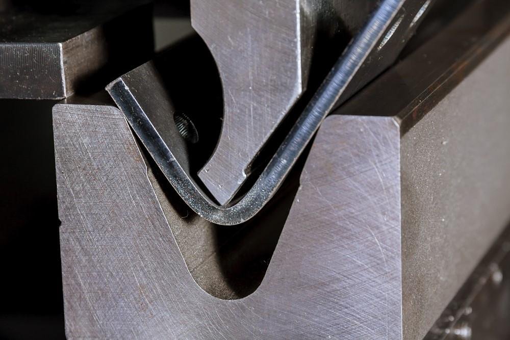
- Lower Die (V-Die) Ratio: Retreat to Advance Aluminum is typically air-bent, and V-opening width determines the natural bend radius (R ≈ V/6).
- Thin Sheets (<3mm): Recommended V-opening is 6–8 times the sheet thickness (6t–8t). For example, a 2mm sheet uses V12 or V16. A smaller V will greatly increase bending pressure and leave severe surface impressions.
- Thick Sheets and Hard Alloys (T6): Expand V-opening to 10–12 times the sheet thickness (10t–12t).
- V-Die Angle: 88° vs 85°
- 88° Die: The standard configuration—suitable for most 5052/3003 applications with moderate springback compensation.
- 85° Die (T6-Specific): For high-volume 6061-T6 processing, use 85° dies. The 88° die’s physical limit is 88°, meaning if springback exceeds 3° (common for 6061), you’ll hit the bottom of the die before reaching the target angle, leaving no room for deeper compensation.

IV. Precision Execution: Zero-Scratch Operation Workflow
In aluminum fabrication—especially for parts destined for anodizing or powder coating—“flawless” isn’t just aesthetic; it’s a marker of process mastery. Aluminum’s oxide layer is hard and brittle, while its base metal is soft and ductile.
This imbalance makes it highly vulnerable to damage from contact with hardened steel dies. Achieving perfect, defect-free forming requires a rigorous system of physical isolation and process control.
4.1 Surface Anti-Marking Techniques (Anti-Marking Strategy)
Once the aluminum surface is scratched by the die, polishing and rework costs skyrocket. Therefore, physical isolation is the most cost-effective defense—its goal is to prevent direct contact between aluminum and die steel.
- Physical Isolation: Urethane Die Film This is the most proven, standardized solution in modern sheet metal shops. A high-strength urethane film is laid across the V-die opening to act as a cushioning barrier.
- Cost Analysis: Although the film costs about 1–2 per meter, it saves several minutes of manual polishing per part. For appearance-critical components, this is a mandatory investment.
- Selection Guideline: Recommended thickness is 0.4mm to 0.8mm. A film that’s too thin can tear under high tonnage, while one that’s too thick will alter the actual bending depth. Operators must therefore recalibrate the CNC’s D-axis (bottom dead point) data—typically adding a depth compensation of 0.1–0.2mm for every 0.4mm increase in film thickness.
- The Ultimate Weapon: Roller Dies (Rolla-V) When working with polished mirror-finish aluminum sheets or highly scratch-sensitive alloys such as 5052-H32, even a taped traditional V-die can leave subtle marks. In such cases, roller dies are the solution.
- Principle Breakthrough: The V-groove of a roller die is made of two rotating semi-cylindrical inserts. During bending, these inserts roll synchronously with the sheet, converting the sliding friction of conventional dies into rolling friction. This mechanical transformation eliminates surface scuffing and drag marks at their root, making roller dies an essential tool for high-end aluminum fabrication.
- Low-Cost Emergency Fix: Tape-on-Bend-Line Method
- Practical Tip: In the absence of dedicated protective film, you can apply standard packing tape or electrical tape along the shoulders on both sides of the V-die opening—the exact points where the material slides into the die.
- Warning: Never apply tape directly to the workpiece. Though it may seem effective, adhesive residue is extremely difficult to remove and attracts dust, which can cause severe adhesion failures in subsequent processes such as painting or coating.
4.2 Equipment Setup and Calibration (Setup)
Treating aluminum like carbon steel is the number one cause of scrap. The sensitive crystalline structure of aluminum demands a deliberate recalibration of machine motion logic.
- Cleanliness Management: Prevent Galvanic Corrosion
- The Hidden Killer: Many workshops use the same dies for both carbon steel and aluminum. If aluminum is bent immediately after steel, residual iron particles can embed into the aluminum surface under high pressure. When exposed to moisture, these particles form microscopic galvanic cells, leading to dark, permanent surface spots that appear on stored parts within weeks.
- SOP: Before switching to aluminum processing, thoroughly clean both upper and lower dies using a dedicated cleaner and scrub with industrial scouring pads to remove oxide and grease. Where possible, establish a die library reserved exclusively for aluminum.
- Speed Control: The Physics of Slow Bending
- Strain-Rate Sensitivity: Aluminum alloys—especially 6061-T6—are highly strain-rate sensitive. Excessive bending speed prevents lattice slip from keeping up with deformation, resulting in brittle fracture.
- Operational Standard: Reduce the ram’s downward bending speed to 30%–50% of the typical carbon steel rate. Allowing sufficient time for dislocations within the metal lattice to move significantly reduces work hardening and prevents rapid crack propagation along the outer bend surface.
- Dwell Time: Stability Through Stillness
- Aluminum’s relatively high modulus of elasticity leads to pronounced springback. Once the ram reaches bottom dead center, set a dwell time of 0.3–0.5 seconds. This brief pause allows partial stress relaxation, reducing springback and stabilizing the crystalline structure for a more consistent final angle.
4.3 Quality Control During Production
Don’t wait until mass production is complete to discover defects. In aluminum fabrication, First Article Inspection (FAI) is the final safeguard against large-scale production errors.
FAI Key Checklist
- Digital Angle Verification: Visual inspection is unreliable for aluminum bends. Use a digital protractor with ±0.1° accuracy. Due to batch-to-batch springback variation, the first piece often requires fine-tuning.
- Monitoring the “Orange Peel Effect”: This is an early sign of fracture. Inspect the outer bend surface under 10× magnification; a coarse, dimpled texture resembling orange peel indicates overstretched or coarsened grains. At this point, either increase the bend radius or switch to a different material batch—otherwise, fatigue failure is inevitable.
- Assessing Inner Surface Impressions: The indentation depth should not exceed 10% of sheet thickness. Excessive marking indicates an undersized V-die opening, which not only mars the finish but also creates severe stress concentration points.
Process Sequence and Dynamic Support
- Inside-Out Sequence: Always bend small inner flanges first, then proceed to larger outer contours. This minimizes interference between the part and the press frame during repositioning.
- Gravity Deformation Prevention: Aluminum’s softness makes long sheets prone to sagging under their own weight, which induces reverse tension along the bend line. For sheets longer than one meter, use a sheet follower or have a second operator support the material to keep it parallel to the die throughout the bend.
V. Advanced Troubleshooting: Complex Defects and Extreme Techniques
In real-world aluminum bending, even strict adherence to standard practices can’t always prevent failures. Material inconsistencies and demanding design constraints can push you into difficult territory.
When conventional methods fall short, you need unconventional, sometimes almost “rule-breaking,” high-level troubleshooting strategies. This chapter reveals the veteran techniques and cutting-edge industrial solutions that can rescue seemingly doomed projects.
5.1 Ultimate Remedies for Cracking and Fracture

When faced with brittle 6061-T6 that must be bent, or when design drawings impose bend radii seemingly defying physics, standard parameter tables are no longer useful. You’ll need a combination of advanced tactics to salvage the project.
- Plan A (Process Adjustment): Oversized V-Die Width Don’t cling rigidly to standard tables. For crack-prone 6061-T6, increase the lower die V-width from the standard 8× sheet thickness (8t) to 10× or even 12× (10t–12t).
- Underlying Logic: A wider V-die naturally produces a larger air-bend radius, which physically reduces the tensile strain rate on the outer bend fibers. This allows the material to complete deformation before reaching its fracture limit. Although this sacrifices bend compactness and increases corner radii, it’s the most straightforward way to preserve part integrity without altering the material.
- Plan B (Material Strategy): 45-Degree Layout Compromise When perpendicular grain orientation (best crack resistance) severely reduces material yield, and parallel orientation (worst crack resistance) guarantees failure, don’t gamble between the two extremes.
- Practical Strategy: Try a 45° diagonal layout. This clever compromise takes advantage of residual slip systems in the crystal structure along the diagonal direction. Empirical data shows that a 45° bend offers crack resistance nearly equal to that of a transverse bend, while providing far greater flexibility for material nesting. It represents the optimal balance between cost (material yield) and quality (defect rate).
- Option C (Physical Approach): The Traditional “Soot Annealing Method” — a time-honored technique among master sheet metal workers. It addresses the challenge of heating aluminum, which shows no visible color change before overheating and melting. When you must perform tight bends or dead edges on hard aluminum, localized annealing is the only reliable solution.
- Operating Procedure:
- Create a Carbon Layer: Ignite an oxy-acetylene torch with acetylene only (no oxygen) to produce a bright yellow, smoky flame. Coat the area to be bent with a uniform layer of black soot.
- Controlled Heating: Turn on the oxygen to achieve a neutral flame, then gently sweep the outer flame over the soot-covered area.
- Visual Temperature Cue: This is the critical moment — when the black soot just burns off completely, revealing a bright metallic sheen, the surface temperature has reached approximately 350–400°C, the optimal annealing range for aluminum.
- Cooling and Forming: Stop heating immediately and allow the part to cool naturally. The treated zone will have softened (O temper), enabling effortless bending without cracking, while the rest of the part retains its high-strength T6 condition.
- Operating Procedure:
5.2 Eliminating the “Orange Peel Effect” and Surface Defects
The “orange peel” effect is more than a cosmetic flaw — it signals improper microstructural deformation within the metal.
- In-depth Cause Analysis: When the outer bend surface appears rough or dimpled like orange skin, there are typically two main causes: (1) the material's grains are excessively coarse, preventing uniform slip between grains during deformation and causing localized bulging; (2) the bend radius is too tight, overstretching the outer fibers and initiating micro-tears.
- Countermeasure: A Counterintuitive Tool Adjustment: If you cannot replace the coarse-grained material due to inventory constraints, try slightly narrowing the V-die opening while significantly increasing the punch radius.
- Rationale: A smaller V-die increases hydrostatic pressure during bending, helping suppress surface grain protrusion. Combined with a larger punch radius, it reduces local tensile strain, thereby improving surface finish.
- Galling Treatment: The Chemical “Soft Touch” – Aluminum debris adhering to steel dies under pressure (build-up) is a major cause of recurring surface damage. Never use sandpaper, files, or grinders to remove it — doing so will compromise the die’s precision geometry.
- Expert Technique: Use a sodium hydroxide (NaOH) solution (strong alkali).
- Procedure: Remove the affected die and immerse it in hot caustic solution. Aluminum, being amphoteric, reacts vigorously with strong alkali to form sodium aluminate and dissolves, while the steel remains unaffected. After a few minutes, the aluminum residue will vanish, leaving the die surface clean and smooth. Rinse thoroughly with water and apply oil immediately to prevent rusting.
- Safety Warning: This reaction generates hydrogen gas and significant heat, and the alkali is highly corrosive. Always wear full protective equipment, including goggles and chemical-resistant gloves.
5.3 Boosting Efficiency with CNC and Automation
The elastic modulus of aluminum can vary widely between batches due to heat treatment fluctuations, making the traditional “one-program-fits-all” method prone to high scrap rates. Modern bending technology is transitioning from experience-driven to data-driven operations.
- Adaptive Bending Systems: A breakthrough technology that marks a turning point in aluminum processing, resolving the long-standing issue of unpredictable springback.
- Technical Principle: Integrated laser or mechanical sensors (such as LVD’s Easy-Form Laser or Trumpf’s ACB) measure the bend angle in real time during the forming process.
- Closed-Loop Control: When the system detects springback, it automatically calculates the deviation and commands the ram to make a micro-level corrective press. This reduces angular error for hard-to-form alloys like 6061-T6 from ±1.5° to ±0.2°, achieving “first-part-right” accuracy without operator intervention.
- Data-Driven Manufacturing: Building an Enterprise-Level “Springback Fingerprint Library”: Don’t rely solely on the nominal values listed in the Material Test Report (MTR). A mature fabrication shop should maintain its own internal material database.
- Implementation Plan: Record the actual springback angles of aluminum sheets from different suppliers and heat numbers. Preload these correction values into your CAM software (e.g., AutoPOL or Radan).
- Practical Value: When the operator scans the incoming material’s barcode, the machine automatically retrieves the corresponding D-axis compensation parameters for that specific batch. In other words, you’re no longer programming for “6061” in general, but for “Supplier A, Batch B of 6061,” eliminating scrap caused by material variability.
VI. Safety, Maintenance, and Sustainable Manufacturing
In aluminum bending, “safety” and “quality” are two sides of the same coin. Aluminum’s unique chemical reactivity and physical sensitivity mean it cannot be treated like ordinary metals.
Ignoring the explosive nature of aluminum dust can lead to catastrophic accidents, while neglecting fine equipment maintenance can undermine precision operations. This chapter builds a protective framework for aluminum processing through risk control, equipment care, and green manufacturing.
6.1 Managing Aluminum Dust Hazards: Beyond Cleanliness — Toward Explosion Prevention
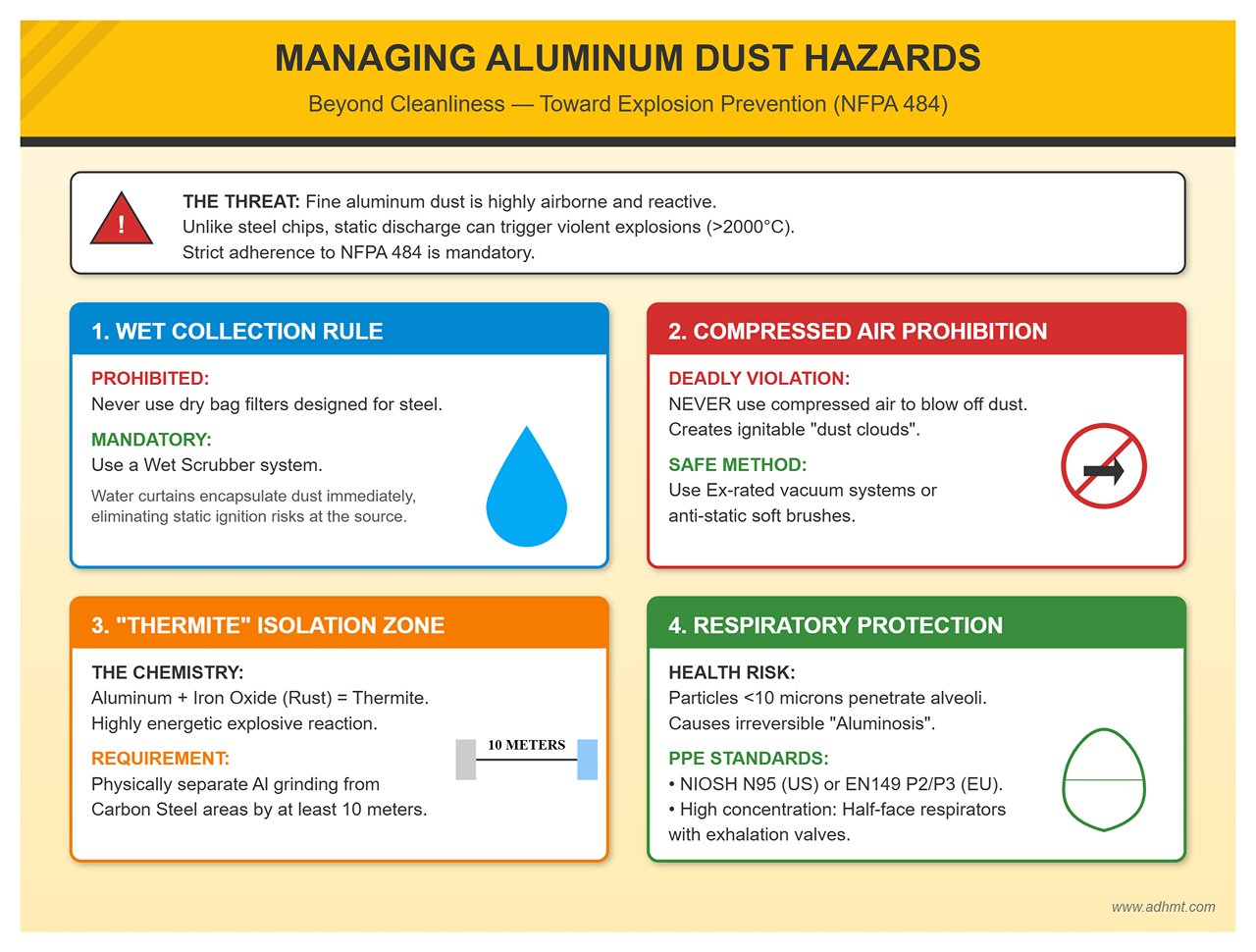
Unlike heavy steel chips, the fine aluminum dust generated during bending or deburring is highly airborne and extremely reactive. At certain concentrations, exposure to static discharge or sparks can trigger violent dust explosions, with combustion temperatures exceeding 2000°C.
- Explosion Prevention Core: NFPA 484 Mandatory Standard
- Wet Collection Rule: Never use dry bag filters designed for carbon steel to collect aluminum dust. A wet scrubber must be used instead, where water curtains immediately encapsulate and settle the dust, eliminating the risk of static ignition at the source.
- Compressed Air Prohibition: One of the most common yet deadly violations in workshops — never use compressed air to blow off aluminum dust from work surfaces or clothing. This creates an easily ignitable “dust cloud” that can explode upon contact with electrical sparks. Always clean using explosion-proof (Ex-rated) vacuum systems or anti-static soft brushes.
- “Thermite” Isolation Zone: When aluminum powder comes into contact with iron oxide (rust), it can form Thermite, a highly energetic chemical explosive. Therefore, the aluminum grinding area must be physically separated by at least 10 meters from any carbon steel grinding area to prevent cross-contamination of metal dust.
- Respiratory Protection: Prevent Irreversible Lung Damage Aluminum dust particles are typically smaller than 10 microns, small enough to penetrate deep into the alveoli and remain trapped there. Prolonged exposure can cause Aluminosis, a form of irreversible lung disease. Ordinary cotton masks provide no real protection. Operators must wear respirators rated NIOSH N95 (US standard) or EN149 P2/P3 (EU standard). In high-concentration areas such as deburring stations, half-face respirators with exhalation valves are strongly recommended.
6.2 Equipment Maintenance for Aluminum Processing: Combating Micron-Level Drift
Aluminum processing demands far greater precision than steel. Due to its high rebound characteristics, maintaining repeatability at the press slide’s Bottom Dead Center (BDC) is critical—typically within ±0.01 mm. Even the slightest mechanical drift can be amplified by aluminum’s physical properties, resulting in defective parts.
- Hydraulic System Thermal Stability Management
- Morning Warm-Up SOP: Cold hydraulic oil is highly viscous and resists flow, causing the slide to respond sluggishly. For aluminum bending, oil temperature equals precision. A strict procedure should be enforced: after startup, run the press in idle mode for 15–20 minutes until the oil temperature stabilizes within the optimal range of 30°C–55°C before performing the first test bend.
- Temperature Drift Compensation: Significant day-night temperature differences can cause hydraulic oil volume changes that shift slide positioning. For high-precision aerospace aluminum processing, use advanced press brakes equipped with closed-loop oil temperature control or recalibrate the D-axis parameters during peak afternoon temperatures.
- Mold Rust Prevention and Borrowing Prohibition
- Cross-Material Contamination: This is the hidden culprit behind mysterious dark spots on aluminum surfaces. Never allow aluminum-dedicated molds to be “borrowed” by carbon steel teams. Even trace amounts of iron dust on the mold surface can embed into aluminum under high pressure. In humid environments, iron and aluminum form micro galvanic cells, leading to surface corrosion during storage.
- Cleaning Protocol: Maintain a dedicated “Aluminum-Only Mold Cabinet.” Before storage, clean molds thoroughly with isopropyl alcohol (IPA) to remove aluminum chips and coolant residues, then apply a thin coat of rust-preventive oil. Avoid chlorine-based solvents, as chloride ions can damage the passive layer on mold steel and trigger pitting corrosion.
6.3 Green Manufacturing: Turning Waste into Profit
Aluminum is among the most valuable recyclable metals in the earth’s crust, requiring only about 5% of the energy used in primary smelting. In lean manufacturing, scrap management directly influences net profit.
- Scrap Classification: The Secret to Doubling Value
- Alloy Segregation Control: Recyclers pay a premium for uncontaminated aluminum scrap. Never mix 5052 (magnesium alloy) with 6061 (magnesium-silicon alloy). Once mixed, the scrap can only be downgraded for low-grade casting applications.
- Visual Management: Place color-coded scrap bins near shearing and press brake stations (e.g., blue for 5xxx series, red for 6xxx series, yellow for pure aluminum). This enables high-value segregation at the source. Pure 6061 scrap typically commands a 30%–50% price premium over mixed scrap.
- Energy Efficiency Revolution: The Servo-Electric Advantage
- In the modernization of aluminum processing equipment, the servo-electric press brake is demonstrating overwhelming advantages.
- Precision Advantage: Servo-electric presses eliminate hydraulic oil expansion and contraction issues, providing instant stability upon startup. Their repeat positioning accuracy can reach ±0.001 mm, dramatically reducing trial waste—crucial for aluminum bending, where rebound control depends on exact penetration depth.
- Energy Consumption Control: Servo-electric presses draw power only during slide movement, with near-zero idle consumption. Total energy savings can exceed 50%, aligning with carbon neutrality goals while significantly lowering per-part operating costs (OPEX).
VII. Summary and Action Guide
Aluminum bending is an art that fuses materials science with precision engineering. If steel bending tests strength, aluminum bending tests intelligence and patience. From microscopic lattice movement to macroscopic machine calibration, every oversight manifests instantly as cracks or dimensional errors. To help you turn theory into shop-floor performance, we’ve distilled the key insights into an actionable quick-reference card and a progressive learning roadmap.
7.1 Quick Reference Card of Core Knowledge
Print and post the following table beside the press brake control panel—it serves as the operator’s final line of defense.
| Key Dimension | Golden Rule | Critical Red Line (DO NOT) |
|---|---|---|
| Bend Radius (IR) | 5052-H32 ≈ 1t; 6061-T6 ≥ 3t; 7075-T6 ≥ 6t | Never use sharp tooling on 6061-T6—it will crack instantly. |
| V-Die Width | Thin sheet (<3 mm): 6–8t; Thick/Hard aluminum: 10–12t | Never use narrow dies for large angles—it causes deep impressions and fractures. |
| Grain Direction | Bend line ⊥ rolling direction (perpendicular is safest) | Never bend parallel to the grain unless the material is annealed. |
| Springback Compensation | Overbend preset: 5052 +1°–2°; 6061 +2°–4° | Do not apply steel’s K-factor (0.44); aluminum requires empirical correction. |
| Surface Protection | Apply 0.4–0.8 mm polyurethane film on the lower die | Never bend on dies contaminated with iron filings—this triggers galvanic corrosion. |
| Operating Speed | Reduce slide speed to 50% of that used for steel | Never perform fast-impact bending—allow lattice structures time to flow. |
7.2 Implementation Roadmap

Whether you’re new to aluminum or an experienced engineer seeking performance breakthroughs, the following progressive roadmap will help you systematically improve yield rates.
Phase 1: Survival Stage (Error Prevention for Beginners)
- Objective: Eliminate batch cracking and severe surface damage.
- Action Items:
- Adopt a “Tiered Tool Selection” Habit: When you see 6061-T6 on the drawing, instinctively reach for a large-radius punch and wide V-die.
- Mandatory Grain Orientation Check: Lock part orientation during nesting to ensure the bend line is perpendicular to the rolling direction.
- Physical Isolation: Always use polyurethane protective film, even for prototypes.
Phase 2: Optimization Stage (Efficiency Enhancement)
- Objective: Achieve precise rebound control and enhance dimensional stability (CPK value).
- Action Items:
- Build a K-Factor Database: For commonly used alloys 5052 and 6061, test the actual unfolding coefficients across various sheet thicknesses and update the default values in the ERP/CAD systems accordingly.
- Implement Slow Pressure Hold: Set a holding time of 0.3–0.5 seconds in the CNC program to release internal stress and stabilize the bending angle.
- Dedicated Die Maintenance: Establish a die area exclusively for aluminum materials, clean regularly with alcohol, and strictly prevent cross-contamination from iron debris.
Phase 3: Mastery Stage (Extreme Process Control)
- Objective: Tackle aerospace-grade hard aluminum and complex aesthetic components to achieve “zero defects.”
- Action Items:
- Master Heat-Assisted Forming: Gain proficiency in localized annealing techniques (flame or induction heating) to overcome bending challenges with 7075 alloy or ultra-small radii.
- Adopt Mark-Free Roller Dies: Invest in roller die systems such as Rolla-V to completely eliminate sliding friction marks and meet the demanding aesthetic standards of high-end electronic products.
- Data-Driven Decision Making: Use tensile test reports from incoming material batches to dynamically adjust bend-depth compensation, transitioning from a “trial-and-error” approach to a “data-driven” methodology.
7.3 Future Trends
The future of aluminum bending technology is accelerating toward greater intelligence and virtualization. We are at a turning point—machines will soon understand materials better than humans do.
- Intelligent, Material-Sensing Press Brakes (IoT Integration) The next generation of press brakes will no longer be blind executors of G-code but intelligent systems capable of perception. With sensors embedded in the back gauge or machine frame, they can detect tensile strength and thickness variations in real time. If abnormal springback is detected during the first bend, the system will automatically infer the batch’s true mechanical properties and instantly adjust the pressing depth for all subsequent operations.
- Digital Twin & Crack Prediction (Digital Twin Simulation) Virtualization will drive trial-and-error costs to zero. Before any physical sheet is processed, full-scale simulation software (such as AutoForm) will not only verify potential interferences but also predict stress concentration points based on material microstructure models. Engineers will see red-highlighted “potential crack zones” on-screen and can optimize radius or die openings digitally—eliminating the outdated “cut and test” routine once and for all.
- Automation and Flexible Manufacturing Cells As skilled sheet metal workers become scarcer, bending robots equipped with vision systems (cobots) will become standard. These robots can tirelessly handle large aluminum sheets and, through force sensors, precisely control follow-up motions—completely eliminating gravity-induced deformation caused by manual handling.
Aluminum bending is a contest of precision against a stubborn metal. Once you grasp the principles outlined here, the sheet in your hands ceases to be a cold piece of metal—it becomes a finely crafted industrial artwork in the making. Now, pick up your caliper and protractor, and head to the workshop to create that perfect bend.


