To master how to form a 0.75 inch radius on a press brake, you must look beyond standard air bending rules. A 0.75-inch (19.05mm) radius often sits in the "uncanny valley" of sheet metal fabrication—too large for standard tooling to form naturally without multi-breakage, yet too small for dedicated rolling equipment. For an in-depth understanding, explore Mastering Press Brake Bend Radius to enhance your forming accuracy and consistency.
This guide deconstructs the physics of large-radius forming, comparing air bending strategies against bottoming and step-bending techniques, to help you eliminate parabolic errors and achieve precise, repeatable results across steel, stainless, and aluminum.
I. Core Insight: Deconstructing the Physical Nature of the 0.75-inch Large-Radius Bend
In sheet metal fabrication, a 0.75-inch (19.05 mm) bend radius is far from being a mere “scaled-up version” of a standard bend. For common thin-gauge materials (such as 16Ga or 14Ga), once the ratio of bend radius (R) to material thickness (T) exceeds 8 (that is, R/T > 8), the underlying bending mechanism undergoes a fundamental transformation.
Without a deep understanding of this physics, operators can easily fall into the trap where all parameters appear correct on paper, yet the finished part ends up neither truly round nor dimensionally accurate. For those seeking more technical insights into the bending mechanism, check out the detailed guide on press brake bend radius provided by ADH Machine Tool.
1.1 Defining the Uniqueness of Large Radius Bending
To successfully achieve a 0.75-inch radius, we must first redefine what we mean by “bending.” It is not merely plastic deformation—it is an elastic-dominant wrapping process.
- Critical Shift in R/T Ratio In a conventional bend, stress is highly concentrated along the bend line, and the material quickly enters plastic flow. However, in a large-radius bend such as 0.75 inch, the stress distribution becomes extremely diffuse. A significant portion of the material remains within the elastic deformation zone, never fully yielding. This shift in physical behavior invalidates many of the standard empirical rules: for example, traditional air bending formulas no longer apply, and the familiar K-factor (neutral axis coefficient) drifts from its stable ~0.33 toward the material center, approaching 0.5. If this adjustment is ignored, the developed length will be miscalculated, producing oversized parts.
- The “Polygon Effect” and Forming Pitfalls This is the most insidious issue in large-radius air bending. When attempting to form a 0.75-inch radius using an air bend, the sheet rarely conforms into a perfect arc. Instead, it tends to form a multi-break (segmented) or parabolic curve. Physically, this happens because the sheet seeks the path of least energy, resisting full contact with the punch tip and causing lift-off. What should have been a single point of contact becomes two, leaving a visibly flat or even angular section at the arc’s center. Consequently, for R0.75 bends, achieving true roundness through simple air bending is nearly impossible unless a bottoming or coining process is used to force full contact. You can also explore how to bend a large radius arc on a press brake to understand the forming process in greater detail.
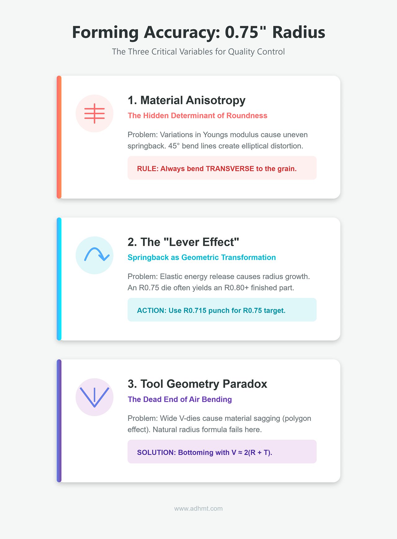
1.2 The Three Core Variables That Define Forming Accuracy
To precisely control the forming quality of a 0.75-inch radius, three critical variables must be tightly managed:
1. Material Anisotropy – The Hidden Determinant of Roundness
Many engineers focus solely on how material grain direction affects cracking, while overlooking its decisive influence on roundness. When the R/T ratio is large, the elastic recovery (springback) response differs drastically between longitudinal (with-grain) and transverse (across-grain) bending due to variations in Young’s modulus.
- Risk of Ellipticity: If the bend line is oriented at 45° or any non-perpendicular angle to the rolling direction, uneven springback can distort the intended circular radius into an elliptical or conical profile after unloading.
- Practical Rule: For a 0.75-inch radius, always bend transverse to the grain. Although this requires higher tonnage, it ensures the most consistent roundness and structural integrity.
2. The “Lever Effect” of Springback
In large-radius bending, springback ceases to be a minor angular correction—it becomes a major geometric transformation.
- Physical Mechanism: Because much of the material remains elastically deformed, once the load is released, a substantial amount of stored elastic energy is suddenly discharged. This not only produces angular springback (often 10–15 degrees) but also causes radius growth.
- Data Warning: A die nominally designed for R0.75 may yield a finished radius of R0.80 or larger after springback. Therefore, die selection must incorporate proactive over-bend compensation—for example, using an R0.715 punch instead of a direct one-to-one match. For further tooling setup guidance, refer to how to set up press brake tooling.
3. The Geometry Paradox of Tool Matching
This is the most frequent dilemma operators face when setting up large-radius bends.
- The Dead End of Air Bending: Using the natural-radius formula (R ≈ 16%V), an R0.75 bend requires a die opening around 4.7 inches. In such a wide V-die, thin sheets tend to sag excessively under their own weight, often producing a parabolic profile rather than a true arc.
- The Necessity of Bottoming: To eliminate the “polygon effect” and force full conformity to the punch, bottoming or urethane die forming is often the only viable solution. In these cases, the die opening should strictly follow the formula V ≈ 2(R + T), and sufficient tonnage must be applied to hydrostatically “lock in” the desired radius.
II. Strategic Choices: Comparing Three Process Routes to Achieve R0.75
For a 0.75-inch (19.05 mm) radius, there is no universally optimal process. Engineers must balance accuracy, tooling cost, and production efficiency.
The following analysis breaks down the physical mechanisms and practical pros and cons of the three primary process routes to help guide precise decision-making.
2.1 Route A: Air Bending — Flexible but Demands High Skill
This method offers the lowest cost and greatest flexibility, but also carries the highest technical risk. In large-radius applications, air bending often creates a deceptive appearance of curvature—a false arc that misleads operators.
- The “16% vs 20%” Rule for V-Die Openings In air bending, the die opening width directly determines the naturally formed internal radius.
- Mild Steel: The natural radius is approximately 16% of the V-die opening. For a target R = 0.75", the required die width is V = 0.75 / 0.16 ≈ 4.68"—meaning a 4.5- to 5.0-inch wide V-die is needed.
- Stainless Steel: Because of its higher yield strength, the natural radius is roughly 20% of the die opening. Thus, for stainless steel, V = 0.75 / 0.20 = 3.75". Caution: Confusing these two ratios can result in significant radius deviation when using the same tooling across different materials.
- The “Parabolic Trap” and Multi-Break Effect When R/T > 10, a sheet pressed into a wide V-die without bottom contact will not form a perfect arc, but a parabolic segment or multi-faceted curve instead.
- Physical Reality: When the sheet metal seeks the path of least deformation energy, it resists fully conforming to the punch tip. Instead, it tends to form a parabolic or elliptical curve—tighter curvature at the bottom (possibly around R0.5) and gentler curvature toward the sides (around R1.0).
- Application Limitations: If aesthetics are the only concern (e.g., equipment housings), this near-circular shape is acceptable. However, for precision fits—such as pipe clamps or bearing shells—this variable curvature becomes a critical defect.
2.2 Route B: Bottoming/Coining – The Preferred Method for High-Precision Mass Production
This is the gold standard in aerospace and high-end sheet metal fabrication. By forcing the material to conform exactly to the die shape, it eliminates the uncertainties of air bending. The trade-off, however, is the significant investment in tooling and the substantial tonnage required.
- The Counterintuitive Logic of Die Matching
- Hardware Requirements: Use a solid punch with an R0.75" radius, paired with a bottom die featuring an arc radius of R0.75" + T (material thickness).
- The Secret of Springback Compensation: An experienced die engineer would never specify a punch labeled exactly R0.750". In large-radius applications, unloading causes a 3–5% radius expansion due to springback. Therefore, a custom punch with R0.715" or R0.720" is ideal—this slight "overcut" ensures the final radius settles precisely at R0.750" after springback.
- The Tonnage Wall and Equipment Safety
- Multiplier Effect: For 16-gauge steel, air bending an R0.75 radius may require only 1–2 tons per foot—very light work. Once bottoming begins, the tonnage demand skyrockets to 3–5 times that of air bending.
- Coining Danger Zone: Never attempt true coining on large radii (i.e., where tonnage reaches 8–10 times that of air bending). The frames and tooling of standard CNC press brakes cannot withstand such extensive high-pressure contact. Doing so risks catastrophic die cracking or ram deformation. For R0.75, bottoming is sufficient—avoid full coining.
- Pro Tip: Urethane Dies – The Cost-Breaking Secret Weapon of Route B
- Principle: Replace the steel bottom die with a high-hardness urethane pad. Acting like an incompressible fluid, it exerts uniform hydrostatic pressure that forces the sheet to conform perfectly to the punch.
- Advantages: You only need a single R0.75 punch, while the urethane die remains universally adaptable. It naturally compensates for springback, eliminates polygonal effects, and leaves no surface marks, making it the ultimate solution for visible or aesthetic components.
2.3 Route C: Step/Bump Bending – The Prototype Fabrication Alternative
When only a standard sharp die is available but an R0.75 sample is urgently required, this becomes your only option. The method approximates a circular arc using a polygonal sequence—essentially applying calculus to metal forming.
- Core Calculation: Chord Height Error and Step Pitch
- Step Pitch Formula: Step Pitch = Arc Length / (Number of Steps - 1)
- Rule of Thumb: For a visually smooth curve (chord height error $\delta < 0.005"$), advance the material every 2–3 mm per bend.
- Example: For R19.05 mm, a 90° arc has an approximate length of 30 mm.
- Recommended number of bends: N ≈ 10–12 steps.
- Each bend angle: approximately 90 / 12 = 7.5°.
- Practical Challenge: Managing Cumulative Error The greatest enemy in step bending is accumulated deviation. A 0.5° error in the first bend can result in a total deviation exceeding 5° after ten bends.
- Operational Tip: Use the CNC system’s “large arc generation” function to automatically calculate all parameters. Pay close attention to adjustments at the first and last bends—improper positioning will create visible flat spots that ruin the arc’s geometry and aesthetic quality.
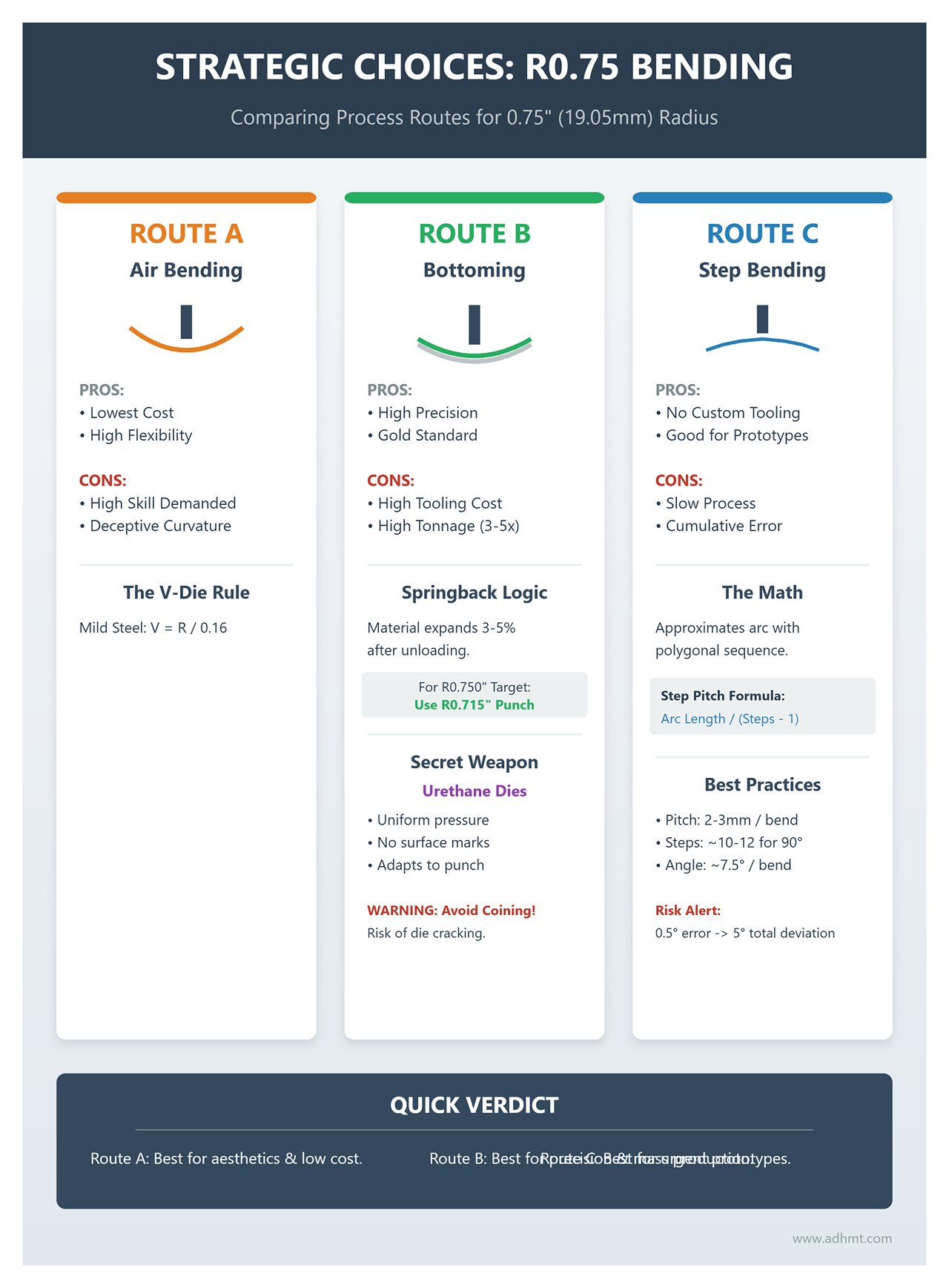
Decision Matrix Summary
To help you make an informed choice quickly, the table below summarizes the key metrics of the three bending methods:
| Dimension | Route A: Air Bending | Route B: Bottoming/Urethane (Recommended) | Route C: Step Bending |
|---|---|---|---|
| Geometric Accuracy | Low (risk of parabolic distortion) | Very high (true circularity, excellent consistency) | Moderate (depends on step density) |
| Tooling Cost | Low (uses standard wide V-dies) | High (requires dedicated round punch/die) | None (uses existing sharp tools) |
| Production Efficiency | High (single-pass forming) | High (single-pass forming) | Low (requires 10+ sequential bends) |
| Springback Control | Difficult (trial-and-error adjustments) | Easy (physical die limits provide compensation) | Difficult (cumulative error hard to predict) |
| Typical Applications | Structural or hidden support parts | Aesthetic parts, precision assemblies, mass production | Prototyping, urgent single parts, nonstandard radii |
III. Tool Selection and Parameter Calculation System
Achieving a precise 0.75-inch (19.05 mm) bend radius is far from a plug-and-play process. Since this falls into the “large radius” category for sheet metal, conventional rules of thumb (like V=8T) fail completely. Without a rigorous, physics-based selection and calculation system, you risk skyrocketing scrap rates—or worse, catastrophic tool failure.
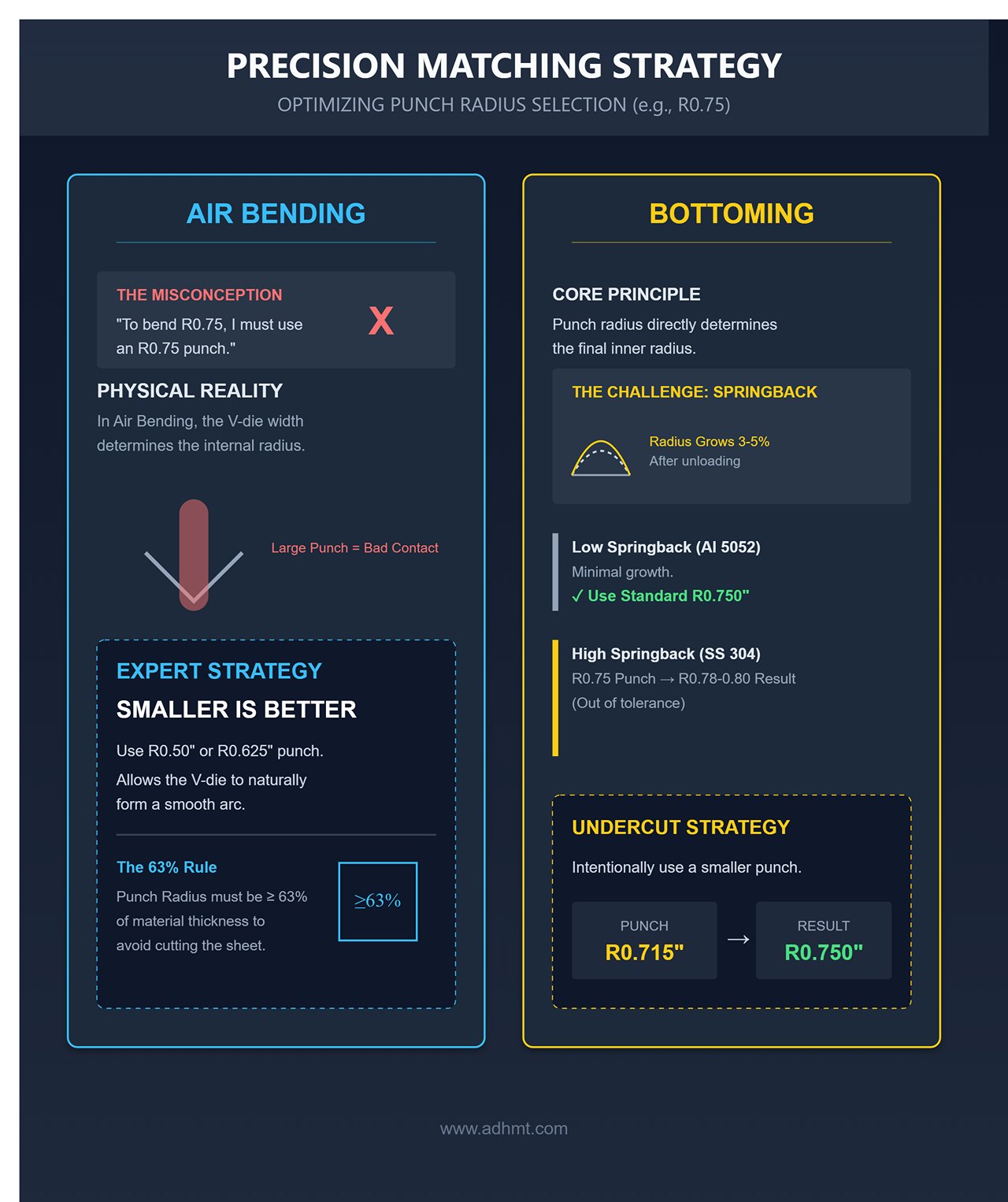
3.1 Precision Matching Strategy for Punch Radius
For large radii like R0.75, the punch is not just a force applicator—it defines the final geometry itself. However, the punch selection strategy depends on the chosen bending route, and this is where even seasoned operators can fall into a subtle but costly misconception.
- Air Bending Selection: The Counterintuitive “Smaller is Better” Approach
- Common Misconception: Many operators assume that to bend an R0.75 radius, one must use an R0.75 punch.
- Physical Reality: In air bending, it’s the V-die width, not the punch radius, that determines the internal radius. Using a punch identical to the target radius (R0.75) creates excessive contact area, which can cause double crease marks or exacerbate polygonal effects during initial forming.
- Expert Strategy: Choose a standard R0.50" (12.7 mm) or R0.625" (16 mm) punch instead. As long as the punch radius is ≥63% of the material thickness, it won’t cut into the sheet. A slightly smaller punch minimizes initial contact area, allowing the wide V-die to naturally produce a smoother, more consistent arc.
- Bottoming Selection – The Art of Geometric Compensation
- Core Principle: In bottoming operations, the punch radius directly determines the final inner radius. However, the “radius growth effect” must be factored in as a compensating variable.
- Low-springback materials (e.g., Aluminum 5052-H32): Because springback is minimal and the material is relatively soft, a standard R0.750" punch can be used directly.
- High-springback materials (e.g., Stainless Steel 304 / Mild Steel): After unloading, the release of elastic energy causes the radius to expand by about 3–5%. Using an R0.75 punch typically results in a finished radius of R0.78 or even R0.80.
- Precision Solution: Implement an “undercut strategy.” Seek or custom-fabricate punches with R0.715" or R0.720" radii (the common R18mm / R0.709" option also works perfectly). This intentional geometric deficit of roughly 0.030" offsets the post-springback radius growth, keeping the final product precisely centered within the R0.750" tolerance band.
3.2 Golden Reference Table for V-Die Opening Calculation
Under R0.75 conditions, the conventional “6–10× material thickness” rule must be discarded. Instead, use a reverse derivation method to determine the proper V-die opening. This is the critical line that separates professionals from amateurs.
- V-Die Calculation for Air Bending (Targeting a Natural Arc) To achieve a natural R0.75 radius, we must determine the V-die opening that produces it organically.
- Formula for Mild Steel: V = R / 0.16 → V = 0.75 / 0.16 = 4.68".
- Conclusion: Choose a 5.0" (127mm) large V-die.
- Formula for Stainless Steel: V = R / 0.20 → V = 0.75 / 0.20 = 3.75".
- Conclusion: Choose a 4.0" (100mm) V-die.
- Warning: For thin sheet metal like 16Ga (1.5mm), using a 5-inch V-die may seem counterintuitive, but physics dictates this as the boundary condition for achieving a natural R0.75 curve.
- Formula for Mild Steel: V = R / 0.16 → V = 0.75 / 0.16 = 4.68".
- V-Die Calculation for Bottoming (Recommended Setup) This is the optimal approach for achieving a high-precision R0.75 radius. The V-die must be tight enough to force the material to conform perfectly to the punch.
- Formula: V = (R_punch + T) × 2 + Clearance
- 16Ga (0.060") Practical Example: V = (0.75 + 0.060) × 2 ≈ 1.62".
- Selection Guidance:
- 1.5" (38.1mm) V-die: Provides excellent forming wrap with slightly higher pressure, but beware of potential pinching hazards.
- 1.75" (44.5mm) V-die: The most recommended “golden dimension.” It delivers reliable bottoming precision while preserving sufficient process margin.
Quick Reference Table for R0.75 Bending Parameters (Example: 16Ga / 1.5mm Mild Steel)
| Target Process | Recommended V-Die Width | Estimated Forming Tonnage | Accuracy Grade | Key Notes |
|---|---|---|---|---|
| Air Bending | 5.0" (127mm) | < 1 Ton/ft | Grade B | Highly prone to springback; suitable for non-critical components |
| Bottoming | 1.75" (44.5mm) | 20–25 Tons/ft | Grade A+ | Best precision combination; requires high tonnage capacity |
| Heavy Bottoming (10Ga) | 2.5" (63.5mm) | 35–40 Tons/ft | Grade A | Close monitoring of die load capacity required |
3.3 Tonnage Load and Machine Safety Calculation
In large-radius bending, danger often hides within seemingly routine operations. The greatest risk is not insufficient total machine tonnage, but overloading the die’s unit bearing capacity.
- Beware of the “Tonnage Trap”
- Air Bending Illusion: Using a 5-inch V-die, the force required to bend 16Ga steel is minimal (less than 1 ton per foot), which can lull operators into complacency.
- Bottoming Shock: Switching to a 1.75-inch V-die and attempting to fully press R0.75 causes the required forming force to increase exponentially.
- Rule of Thumb: Bottoming tonnage is typically 3–5 times that of air bending under the same V-die width—or even higher. For 16Ga steel in a 1.75" V-die, air bending requires about 3 tons/ft, but achieving a perfect R0.75 bottomed form demands 15–25 tons/ft of output.
- Die Safety Limit
- This is a commonly overlooked but critical hazard. The typical load capacity of hardened V-dies is roughly 1 ton/ft per millimeter of V width.
- Safety Calculation: For a 1.75" (44mm) V-die, the safe limit is approximately 45–50 tons/ft.
- Danger Zone Alert: Attempting to coin thicker materials (such as 10Ga or 1/8") to achieve R0.75 can escalate the tonnage requirement to 80–100 tons/ft. This not only risks severe machine damage but can fracture the 1.75" V-die itself, potentially causing flying debris and serious injury.
- Action Directive: Before performing large-radius bottoming, always consult the die manufacturer’s “Maximum Allowable Tonnage (Max Tons/ft)” and ensure your setup does not exceed 80% of that rated capacity.
IV. Advanced Field Practice: Material-Specific Adjustment Guide
After mastering the underlying physics, we must confront the most unpredictable variable in production—material characteristics. The same R0.75 tooling setup may yield flawless bends in mild steel, overshoot the radius in stainless steel, or even crack aluminum.
This chapter provides a differentiated strategy from micro-level physics to macro-level parameter optimization across three mainstream material types. For more detailed specifications and technical data, you can download official brochures from ADH Machine Tool.
4.1 Mild Steel – Baseline Parameters and Risk Avoidance
Mild steels (such as A36, 1018, or cold-rolled sheet) are often considered the “comfort zone” for bending. However, under large-radius conditions like R0.75, they are not risk-free. Their relatively low yield strength helps control springback but also tends to expose geometric discontinuity issues during air bending.
- Characteristic Analysis:
- Low Springback Baseline: For mild steel, the springback angle typically stays within 0.75° to 1.0°, meaning you don’t need to make aggressive die angle compensations.
- Forming Pitfall: Because of its softness, mild steel tends to collapse at the initial stage of air bending in wide V dies (e.g., 5-inch openings). The resulting curve often appears parabolic rather than perfectly circular.
- Practical Strategy:
- Air Bending Optimization: Although narrower V dies can theoretically be used, for a natural R0.75 bend it’s best to adhere strictly to the $V = 8T$ to $V = 10T$ guideline. For 16Ga material, a 0.8" to 1.0" V die yields a smoother, more accurate radius.
- Friction Management: The anti-rust oil film on mild steel acts as a natural lubricant during large-radius bends. Never wipe the sheet completely dry—a thin oil layer helps reduce resistance as the sheet flows over the V die shoulders, effectively preventing polygonal edges.
4.2 Stainless Steel (304/316) — Conquering the Challenge of Springback and Hardening
This is where large-radius bending becomes truly demanding. Stainless steel’s high yield strength and pronounced work-hardening behavior make its post-bend performance highly unpredictable. Using parameters suited for mild steel will inevitably lead to failure.
- Challenge: Amplified Springback and Radius Drift
- Angle Springback: For 304 stainless steel, the springback angle is typically 2–3 times that of mild steel, around 2° to 3°, and can reach up to 5° depending on the rolling direction.
- Radius Growth: A commonly overlooked issue. Upon unloading, the strong elastic recovery not only changes the bend angle but also enlarges the bend radius. Using a R0.750" punch often results in a final inner radius of R0.78" to R0.80".
- Countermeasure: The Counterintuitive “Geometric Undercut” Approach
- Punch Selection Rule: Never use a standard R0.75 punch. To offset radius growth, you must intentionally “undersize” the punch radius. Recommended range: R0.625" (16mm) to R0.70" (17.8mm). This 5–10% difference ensures that, after springback expansion, the final radius falls precisely within the R0.75 tolerance band.
- Dwell Time: Hold at bottom dead center for 0.5 to 1.0 seconds. This isn’t wasted time—it allows the material’s crystal lattice to reorganize and release part of the stored elastic energy, significantly reducing springback.
- Surface Protection: Stainless steel’s hardness can easily scratch ordinary V die shoulders, leading to die wear and visible lines on the part. Always use TiCN-coated dies, or place a 0.015" polyurethane film under the lower die for protection.
4.3 Aluminum Alloy (5052/6061) — Strategies Against Cracking and Orange Peel

Bending aluminum alloys involves a delicate balance: preventing brittle fracture in hard aluminum (6061) while avoiding orange peel texture in soft aluminum (5052).
- Managing the “Explosion” Risk of 6061-T6:
- Grain Direction Is Critical: Although R0.75 is far larger than the recommended minimum bend radius (usually 3T–4T), bending parallel to the grain can still cause microcracks along the outer arc. Strongly recommended: Always bend transversely to the grain.
- Annealing Technique: If design constraints require bending parallel to the grain, locally heat the bend area with an oxy-acetylene torch to anneal it to T4 condition, then allow natural aging after bending.
- Orange Peel and Impression Elimination:
- Phenomenon Explained: During large-radius stretching, coarse or overstretched grains can create a rough “orange peel” texture on the outer surface. Soft aluminum is also prone to deep shoulder impressions from the V die.
- Comprehensive Solutions:
- Material Substitution: When design allows, choose 5052-H32. It offers far superior formability than 6061 and greatly reduces orange peel tendency.
- Shoulder Radius: Replace sharp standard V dies with large-radius dies where shoulder radius $R_d > 1.5T$, helping distribute contact pressure.
- Mandatory Urethane Film: For aluminum parts with visible surfaces, urethane protective film is a must. It prevents impressions, acts as a lubricant, and promotes smoother material flow—reducing orange peel formation.
📊 Quick Reference Table (for 16Ga/1.5mm Material, Target R0.75)
The table below summarizes key parameter differences among the three materials when aiming for precise R0.75 forming, serving as a quick setup guide for operators.
| Material Type | Recommended Punch Radius (Punch R) | Expected Springback | Key Operation Tip (Expert Insight) |
|---|---|---|---|
| Mild Steel | R0.75" (bottoming) or R0.5" (air bend) | 0.75° ~ 1.0° | Maintain a light oil film; use natural springback to fine-tune roundness. |
| SS 304 | R0.625" ~ R0.70" | 2.5° ~ 4.0° | Overbend both radius and angle; extend dwell time. |
| Al 6061-T6 | R0.75" | 1.5° ~ 2.0° | Never bend parallel to grain; use higher tonnage for stable results. |
| Al 5052-H32 | R0.75" | 0.5° | Best forming performance; always use protective film to avoid marks and orange peel. |
V. Standardized Operating Procedure (SOP): From Preparation to First Article
Once the theoretical parameters are set, the real challenge lies in translating numbers into flawless physical results. For large-radius bends like 0.75 inches, even minor variables—such as subtle thickness differences or hydraulic oil temperature fluctuations—can be magnified by geometric leverage.
Establishing a rigorous, military-grade SOP is the only way to ensure consistent quality from the first to the thousandth part. To ensure your press brake delivers optimal performance, you can contact us for professional technical support and consultation.
5.1 Preparation Stage: Environment and Material Verification
Before pressing the start button, all hidden variables must be systematically eliminated. This isn’t just about precision—it’s about protecting the tooling itself.
- Machine Geometry Calibration:
- Ram Parallelism: For large-radius bends, synchronization between the left and right sides of the ram must be controlled within ±0.001" (0.02 mm). Because the R0.75 die has a wide contact area, even minor ram tilt can cause one side to meet the angle specification while the other overbends, potentially leading to uneven loading and die cracking.
- Backgauge Perpendicularity: Verify alignment between the backgauge fingers and the die centerline. Large-radius bends often involve long flange lengths, and even a 0.5 mm misalignment in the backgauge can cause noticeable taper along the bend line, preventing proper part assembly.
- Precision Die Alignment:
- Three-Point Alignment Method: Never align the tooling solely at the machine center. Calibration must be performed at the left end, center, and right end using a dial indicator or precision alignment block to ensure the upper and lower die centerlines remain within < 0.05 mm deviation across the entire length. The R0.75 die endures significant lateral forces during bottoming; even slight eccentricity can cause one-sided wear and asymmetric bend profiles.
- Material Verification and Data Update:
- Thickness Butterfly Effect: In air bending, a variation of just ±0.004" (0.1 mm) in sheet thickness can produce a final angle deviation of approximately 3°.
- Mandatory Action: Before loading each new batch of sheet metal, measure the actual thickness with a micrometer (for instance, a nominal 1.5 mm sheet may read 1.42 mm). Enter the measured value precisely into the CNC system’s “Material Thickness” parameter so the machine can automatically recalculate the Bottom Dead Center (BDC). This step is crucial for achieving first-piece accuracy.
5.2 Core Operation: Five-Step First-Piece Bending Method

Do not expect a perfect 90° bend on the first try. With large-radius bending, chasing instant perfection often leads to scrap. Follow the “Five-Step Trial Bend” precisely:
1. Under-Bend Safety Check:
- Setup: Raise the CNC-calculated Y-axis depth by 0.030"–0.050", or set the target bend angle to 85° for a 90° bend.
- Purpose: This is a low-risk probing step. Observe material flow within the R0.75 die, ensuring no deviation or abnormal noise, and monitor the machine’s tonnage load to confirm it remains within the safe operating range.
2. Initial Radius Check (Go/No-Go):
- Tooling: Use an R0.75 Radius Gauge and perform a Light Gap Check.
- Diagnosis: Although the angle may not yet be correct, inspect the curvature for true roundness. If the arc top already shows flat spots or polygonal edges, the V-die opening is likely too narrow or the wrong bottoming technique is being used. Continuing to press will only worsen the defect—stop immediately and review die selection.
3. Springback Quantification:
- Action: Gradually increase downward pressure until the workpiece reaches 90° under load.
- Record: Release the ram and measure the free angle (e.g., it springs back to 92.5°).
- Input: The difference (2.5°) is the actual springback value. Enter this directly into the CNC’s “Springback Compensation” or “Angle Correction” library rather than manually adjusting Y-axis depth.
4. Micro-Adjustment:
- Angle Deficiency: For manual fine-tuning, modify the Y-axis depth by 0.002" (0.05 mm) per iteration. Note that large-radius dies are less depth-sensitive than sharp dies, so larger adjustments may be needed to produce visible angle changes.
- Radius Oversize: This issue cannot be corrected by parameter adjustment. It typically indicates an oversized punch radius (without accounting for springback expansion). The only solution is to switch to a smaller punch—e.g., from R0.75 to R0.70.
5. Process Locking:
- Standard: The first-piece qualification is achieved only when three consecutive test bends show angle deviations within ±0.5° and pass radius gauge inspection.
- Record: Save the CNC program and log the current hydraulic oil temperature, die number, and sheet batch number to establish a baseline for production.
5.3 Process Control During Mass Production
Passing the first-piece inspection is just the beginning. During mass production, large-radius bending is prone to quality fluctuations caused by thermal drift and tool wear.
- Thermal Compensation Management:
- Phenomenon: As the machine runs, hydraulic oil temperature may rise from 20°C in the morning to 45°C in the afternoon. Thermal expansion of the frame can cause micron-level shifts in the ram’s bottom dead center, resulting in angle changes of 0.5°–1.0° for sensitive large-radius bends.
- SOP: Warm up the machine for at least 15 minutes before starting each day. During production, recalibrate the first-piece angle every hour. If the CNC offers real-time thermal compensation, keep it enabled at all times.
- Inspection Protocol:
- Recommended Frequency: Perform sampling inspection every 50 pieces or every 30 minutes.
- Inspection Focus: Beyond angle measurement, always use both tactile and visual checks on the arc surface. Large-radius bends have extensive contact areas and are highly susceptible to galling. If the arc surface becomes rough or develops small particles, stop immediately and clean the V-die shoulders; otherwise, subsequent parts will all suffer surface damage and be scrapped.
VI. Troubleshooting and Expert-Level Solutions
When tackling a 0.75-inch large-radius bend, even the most meticulous parameter setup can be challenged by subtle variations in material batches or machine conditions.
The true distinction between an expert and a regular operator lies not in avoiding problems, but in the ability to quickly identify the underlying physical causes and deliver a precise, surgical-level corrective solution.

6.1 Dimensional and Shape Defect Troubleshooting Matrix
This diagnostic matrix is specifically designed for extreme conditions where $R/T > 10$. Pay particular attention to the Physical Root Cause Analysis column—it exposes the subtle variables that often escape the notice of experience-based operators.
| Symptom | Root Cause | Expert Solution |
|---|---|---|
| Actual radius > 0.80" (Severe Overshoot) | Springback out of control: The material’s yield strength is higher than expected (e.g., hardened stock used), causing excessive elastic recovery after unloading, which enlarges the arc. | 1. Over-bend Compensation: Replace with a smaller punch (R0.625"–R0.70") to reserve 5–10% geometric allowance for springback. 2. Bottom Dead Hold: Extend the dwell time at bottom dead center to 0.5–1.0s to allow lattice rearrangement and “lock” the shape. |
| Actual radius < 0.70" (Too small/sharp) | Misjudged sag effect: During air bending, theoretical V-die dimensions were used without accounting for the plate’s natural sag under gravity in wide-open dies, resulting in tighter wrapping. | 1. Increase V-die width: Switch from 4" to 5" to provide broader support points, enlarging the natural bend radius. 2. Raise Punch Correction: Lift Y-axis depth by 0.010"–0.015" to reduce penetration, relying fully on air-bending curvature formation. |
| Polygonal edges (Multi-breakage) | Contact separation (Lift-off): In large-radius air bends, the sheet seeks a minimum energy path, resisting full contact with the punch and forming “two-point contact” rather than full wrap. | 1. Ultimate Fix: Use a urethane pad die, whose near-incompressible nature provides uniform back pressure for full contact. 2. Forceful Fix: Switch to a smaller V-die (e.g., 1.5") for bottoming mode—use high tonnage to press and flatten corners (ensure tonnage safety). |
| Uneven radii at part ends (Taper) | Machine deflection: Large-radius dies have wide contact areas; high tonnage causes the ram center to bow upward, leading to insufficient angle at the center and over-bending at ends. | 1. Dynamic Deflection Compensation: Manually add 0.002"–0.004" crowning compensation in the CNC system. 2. Quick Fix: Insert 0.003" copper shims or industrial paper under the die’s central zone to manually offset the deflection. |
| Outer surface orange peel | Grain coarsening/overstretching: Aluminum alloys (especially 6061) exhibit grain boundary slip under severe tension, or the V-die shoulder radius is too small, restricting material flow. | 1. Material Substitution: If design permits, replace 6061-T6 with more formable 5052-H32. 2. Shoulder Refinement: Polish V-die shoulders to Rd > 1.5T to reduce flow restriction. |
| Inner surface deep die marks | Long-distance frictional galling: In R0.75 bends, sheet travel within the V-die is over three times that of sharp bends; frictional heat can cause micro cold welding. | 1. Physical Isolation: Always use a 0.015" thick urethane protection film. 2. Rolling vs. Sliding: If budget allows, adopt Roll-V dies (roller type) to convert sliding friction into rolling contact and eliminate marking entirely. |
6.2 Tooling Maintenance and Life-Cycle Management
In R0.75 production, tooling should not be treated as consumables but managed as precision instruments. The unique stress patterns of large-radius bending produce wear characteristics distinct from conventional dies.
- Profile Monitoring for Radius Wear (“Flat-Top” Detection):
- Risk Mechanism: Unlike sharp dies that wear at the tip, R0.75 punches wear at the center of the arc. Prolonged high-tonnage bending of stainless steel flattens the punch top (flat spot), distorting the arc into a “flat-top rounded-side” shape—an error nearly impossible to correct through parameter adjustments.
- Inspection SOP: Establish a quarterly inspection routine. Use a standard R0.75 radius gauge and backlight to examine the punch top. Any uneven light gaps—especially visible at the center—require immediate precision regrinding or disposal.
- Anti-Galling Lubrication Strategy:
- Physical Mechanism: During long sliding travel into V-dies, galvanized or aluminum sheets easily cold-weld zinc or aluminum particles onto die shoulders under high pressure and frictional heat, forming pickups. These not only scratch subsequent parts but also alter die friction coefficients, causing angle instability.
- Lubrication Principle:Dry bending is strictly forbidden for large-radius operations.
- Before Production: Apply high-viscosity drawing oil or spray a dry lubricant (e.g., molybdenum disulfide) on V-die shoulders to form a micro isolation layer.
- During Production: At the end of each shift, clean V-die shoulders with red industrial-grade Scotch-Brite pads and degreaser.
- Prohibition: Never use sandpaper or angle grinders on die surfaces! Doing so destroys the die’s hardened layer and precise geometry, leading to irreversible damage.
VII. Advancement and Summary: Moving Toward Zero-Defect Production
In sheet metal bending, R0.75 (19.05 mm) large-radius forming is a true watershed—it separates traditional craftsmen who rely on tactile experience from modern engineers guided by data.
Once we master the physics, choose the correct process route, and implement strict process controls, the final step is to introduce intelligent tools and standardize best practices.
The goal goes beyond producing a flawless part—it’s about building a replicable, zero-defect production system.
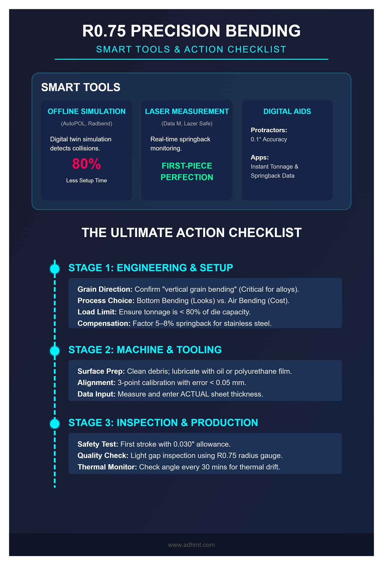
7.1 Recommended Smart Assistance Tools
In the era of Industry 4.0, relying on trial-and-error to conquer large-radius springback is not only inefficient but wasteful for costly materials. The following three categories of intelligent tools act as precision multipliers for R0.75 forming accuracy:
- Offline Bending Simulation Software:
- Pain Point Addressed: R0.75 dies are typically massive (especially 5-inch V-dies), and during actual processing, they easily collide or interfere with complex flanges or machine backgauges.
- Recommended Value: Use software such as AutoPOL, Radbend, or MetaCAM to simulate the entire bending process within a digital twin environment before cutting. These tools accurately predict developed lengths for large-radius bends (including K-factor corrections) and automatically detect potential collisions. For R0.75 projects, offline programming can reduce on-site adjustment time by up to 80%.
- Real-time Laser Angle Measurement System:
- Pain Point Addressed: Variations in material hardness between batches can cause unpredictable springback angles, making manual adjustments difficult for operators.
- Recommended Value: Press brakes equipped with Data M (Laser Check) or Lazer Safe (Iris Plus) systems can continuously monitor springback dynamics during the bending process. The system automatically measures the actual angle after unloading and commands the ram to perform a micron-level “secondary press” for compensation. For stainless steel with high springback and large-radius bends, this is the ultimate tool to achieve “first-piece perfection.”
- Portable Digital Protractors and Springback Calculators:
- Pain Point Addressed: Traditional radius gauges only provide qualitative results (pass/fail) and cannot quantify deviation.
- Recommended Value:
- Digital Protractors: With an accuracy of 0.1°, they allow for rapid verification of the first-piece bending angle.
- Brand Apps (such as Trumpf or Amada’s Bending Guide): By entering material type and R0.75 parameters, these apps use extensive material databases to instantly provide accurate tonnage requirements and springback estimates—eliminating the need for tedious manual calculations.
7.2 The Ultimate Action Checklist
To ensure every R0.75 bend meets perfection, print and post this checklist beside your machine’s control panel. It condenses countless hours of hands-on experience into a practical guide:
Stage 1: Engineering & Setup
- Texture Confirmation: Does the drawing specify “vertical grain bending”? (Especially critical for aluminum alloys and high-strength steels.)
- Process Selection: Pursuing flawless appearance? Choose bottom bending (R0.715 punch + 1.75" V-die). Seeking cost efficiency? Opt for air bending (R0.5 punch + 5.0" V-die).
- Tonnage Verification: Is the required tonnage less than 80% of the die’s maximum load capacity? (Never perform R0.75 coining on thick plates.)
- Compensation Setup: For stainless steel, has a 5–8% radius springback compensation been factored into punch selection?
Stage 2: Machine & Tooling
- Cleanliness: Have all oil and metal debris been completely removed from the V-die shoulders?
- Lubrication: Are the V-die shoulders coated with drawing oil or covered with a polyurethane film to prevent marking?
- Alignment: Was the die centerline calibrated using the “left-center-right” three-point method (error < 0.05 mm)?
- Thickness Measurement: Has the actual sheet thickness been measured and entered into the CNC system to update the bottom dead point?
Stage 3: Inspection & Production
- Underpressure Test: Was the first stroke performed with a 0.030" allowance to confirm no interference and smooth machine operation?
- Light Gap Inspection: Use an R0.75 radius gauge with backlighting to check if the arc is smooth and continuous, free of polygonal edges.
- Springback Entry: Measure the actual springback angle and record it in the CNC compensation library.
- Thermal Drift Monitoring: During mass production, check the bending angle every 30 minutes to ensure that hydraulic oil temperature rise hasn’t caused drift.
Conclusion
Bending with an R0.75-inch radius may appear to be a simple geometric task, but it is in fact a sophisticated interplay of material mechanics, tooling design, and precision processing. From understanding the physics of elastic dominance to choosing counterintuitive compensating dies and executing meticulous process control, excellence at every stage culminates in the perfect final product.
When you can confidently master the balance between a “large radius” and “thin sheet,” you’re not just operating a machine—you’re redefining the art of metal forming through a craftsman’s lens. May this guide become your most trusted workshop companion, helping you achieve that crisp metallic resonance that signifies perfection with every bend.


