Press brake die selection for aluminum is no longer a matter of rule-of-thumb; it defines whether your bends are predictable, crack-free, and economically viable. Modern studies and industrial practice alike highlight that the “right” die now has to match alloy grade, thickness, surface requirements, and even future digital control of springback.
This article builds on that reality to walk from material physics and die geometry, through hardware and troubleshooting, to an ROI-driven roadmap for intelligent tooling decisions.
I. Cognitive Reframing: Building a “Non-Steel Mindset” for Aluminum Processing
1.1 Breaking Inertia: Why “Steel Thinking” Is the Biggest Trap in Aluminum Bending
In precision sheet metal fabrication, 90% of aluminum bending failures don’t stem from machine inaccuracy, but from engineers trying to apply the logic of mild steel to aluminum. This mental inertia not only drives up scrap rates but also leads to misguided tooling choices. To truly master aluminum bending, one must first rebuild their understanding of the material at a fundamental, physical level.
1. The Contrast Between “Chaotic” and “Linear” Springback
Mild steel’s springback is typically linear and predictable. Aluminum, however, behaves far less obediently. Influenced by both work hardening and yield strength fluctuation, its springback is highly non-linear. For cold-worked alloys like 5052-H32, even minor variations in rolling tension within the same batch can cause significant differences in rebound angle.
💡 Key Difference: In steel bending, the V-die opening largely determines the inner bend radius (in air bending, the natural radius is roughly 16% of the V width). In aluminum, however, the punch tip radius dominates the outcome. Using a sharp punch (e.g., R0.8 mm) suitable for steel on 6061-T6 won’t yield a smooth curve — it will create stress concentrations at the point, leading directly to intergranular cracking.
2. The Abrasive Nature of Aluminum Oxide
Steel oxide layers are loose and brittle, but the aluminum oxide (Al₂O₃) film on aluminum is as hard as ceramic — nearly the same as ruby.
⚠️ The Hidden Assassin: When you bend aluminum with standard steel dies, you’re effectively rubbing a soft metal core wrapped in “sandpaper” (the oxide layer) against the die surface. This leads to severe galling (pickup) — aluminum particles cold-weld to the die and scratch every subsequent workpiece. Steel bending logic says “harder dies are better”; aluminum bending experience insists “friction control and anti-adhesion are king.”
3. Critical Sensitivity to Grain Direction
When bending mild steel, grain direction is often ignored. With aluminum, it’s a life-or-death factor. Rolling elongates grains, creating strong anisotropy.
🛠️ Field Rule: Bending parallel to the grain “tears” grain boundaries, dramatically increasing cracking risk. Bending perpendicular to the grain disperses stress. If you don’t adjust the V-die width or change the layout orientation, alloys like 6061-T6 will crack mercilessly along the outer bend line.
1.2 The Bending Personalities of Aluminum Alloys
“Aluminum” isn’t a single material—it’s a diverse family with distinct personalities. Tool selection must be based on the specific alloy grade and temper; otherwise, you’re chasing illusions. Below is a personality map of major aluminum alloys and their corresponding tooling strategies:
| Alloy & Temper | Industry Nickname | Bending Personality Profile | Key Tooling Strategy |
|---|---|---|---|
| 5052-H32 | “The Workhorse” | Exceptionally well-balanced. A magnesium-based alloy with moderate strength and excellent ductility. It’s the most bendable non-heat-treatable alloy. Can typically handle small radii (~1t) without cracking. | Standard Strategy: You can use near-steel V-width standards (6t–8t), but opt for coated dies (TiCN) or polyurethane films to prevent surface scratching. |
| 6061-T6 | “The Diva” | Deceptively strong but fragile. While widely used for its high strength, its ductility plummets in the T6 temper. Precipitates lock the grains, making it extremely notch-sensitive — bending it is like folding a dry cracker. | Defensive Strategy: 1. Use large radii: minimum 3t–4t (for sheets >3 mm). 2. Increase V width: abandon the 8V steel rule—go 10V–12V to ease stress. 3. Match punch radius: avoid sharp tips; use large-radius punches. |
| 6061-T4 / W | “The Flexible One” | Time’s ally. The T4 temper (naturally aged) is far more ductile than T6. The W temper (freshly quenched, unaged) offers a few hours of a “golden bending window” — soft as butter, then hardens over time. | Advanced Strategy: If the design needs small radii with high strength, bend in the T4 or O temper, then artificially age to T6. This is standard aerospace practice. |
| 7075-T6 | “The Rock” | Approach with caution. A zinc-based, ultra-high-strength alloy — as strong as steel but extremely brittle. Room-temperature bending is nearly destructive. | Special Strategy: Never bend at room temperature. Either anneal to O temper or apply warm forming. If bending is mandatory, use very large radii (≥6t). |
| 3003-H14 | “The Softie” | Exceptionally forgiving. A manganese-based alloy that almost never cracks — even 0R bends are possible. However, it’s low strength and prone to galling. | Surface Strategy: Cracking isn’t the issue; appearance is. Use non-marking dies (polyurethane, ball-type V-dies, or rotary dies) to avoid surface indentation. |
🚀 Insider Tip: Many engineers select dies based solely on tensile strength, but in aluminum bending, elongation and the yield-to-tensile ratio are the true survival metrics. 5052’s elongation exceeds 20%, while 7075-T6 may fall below 11%. This difference directly defines your minimum bend radius threshold.
II. Core Algorithms: Calculating Tooling Parameters Based on Material Properties
When working with mild steel, many engineers swear by the universal “V = 8t” rule. In aluminum fabrication, clinging to that rule isn’t just lazy—it’s disastrous. Aluminum’s unique physical behavior demands a highly adaptive approach to die selection.
This section reveals the reasoning behind the empirical formulas, helping you set each process parameter with precision.
2.1 Dynamic Principles for Calculating V-Die Opening
The choice of V-opening for aluminum is far from fixed—it must strike a delicate balance between forming precision and fracture risk. Depending on the alloy’s hardness, entirely different calculation strategies are required:
- Soft aluminum (5052-H32, 3003) — The “Compact Rule”
These alloys offer excellent ductility and can withstand significant plastic deformation. To achieve a smaller inner radius (Inner Radius) and superior flatness, you can confidently reduce the V-opening.
Expert Formula: V = 6t (when sheet thickness t < 3mm)
Practical Note: When bending 5052 with a 6V die, the inner radius will be crisp—about 0.8–1.0 times the sheet thickness. But be aware: a narrower V-opening means higher localized pressure. Always inspect the die shoulder radius for surface smoothness, and use protective film if necessary, as aluminum pickup will form roughly twice as fast as it would with an 8V die.
- Hard aluminum (6061-T6, 7075) — The “Forgiveness Rule”
For high-strength T6-tempered alloys, the main goal of choosing the V-opening is no longer defining the R-radius—it’s about diffusing bending stress. Using an 8V die on 6061-T6 forces the material to undergo extreme deformation over a very short arc length, instantly exceeding the grain boundary bonding strength.
Expert Formula: V = 10t ~ 12t
Practical Note: Expanding the V-opening to 10t–12t increases the natural forming radius, but this adjustment is often the only physically viable solution that prevents cracking.
- Air Bending — The “14% Rule”
This is the golden ratio for predicting the natural forming radius (Natural Radius) of aluminum. In free bending, the material forms while suspended, and the inner radius (Ir) maintains a fixed proportion to the V-opening. For steel, the ratio is about 16%, but because aluminum has a lower elastic modulus, the ratio decreases:
Aluminum Natural Radius Estimate: Ir ≈ V × 14%
Application Example: If the customer’s drawing specifies an R3.0 corner, you can calculate the required V-opening: V = 3.0 / 0.14 ≈ 21.4 mm. In this case, choosing a V20 or V22 die is optimal.
Critical Warning: Never attempt to “coin” an R3 radius using a punch tip of R3. This will cause severe surface indentation and structural damage in aluminum parts.
2.2 Minimum Inner Bend Radius (Min IR) and Fracture Threshold
The minimum bend radius isn’t a recommendation—it’s a physical red line. Crossing it will result in surface defects like orange peel or even intergranular cracking.
Below is a safety threshold table based on extensive empirical data (values expressed in sheet thickness multiples, T):
| Alloy Grade | Perpendicular to Grain | Parallel to Grain | Risk Level |
|---|---|---|---|
| 5052-H32 | 0.8t ~ 1.0t | 1.0t ~ 1.5t | 🟢 Low Risk |
| 6061-T6 | 3.0t ~ 4.0t | 4.0t ~ 5.0t | 🔴 High Risk |
| 7075-T6 | 4.0t ~ 6.0t | Bending Prohibited (or requires hot forming) | ⚫ Extremely High Risk |
| 3003-H14 | 0t ~ 0.5t | 0.5t ~ 0.8t | 🟢 Low Risk |
⚠️ Critical Warning: The 63% Sharp Bend Limit
Regardless of alloy type, when the punch tip radius (Punch Radius) is smaller than 63% of the sheet thickness (0.63t), the bending mechanism changes fundamentally—from bending to creasing. At this point, the punch tip no longer guides material flow but instead acts like a blunt cutter penetrating the sheet. For 6061-T6, this creates a deep stress groove on the inner bend surface, which becomes the origin of fatigue fractures. Rule of thumb: for aluminum bending, keep punch tip radius ≥ 1t.
2.3 Quantitative Control of Springback
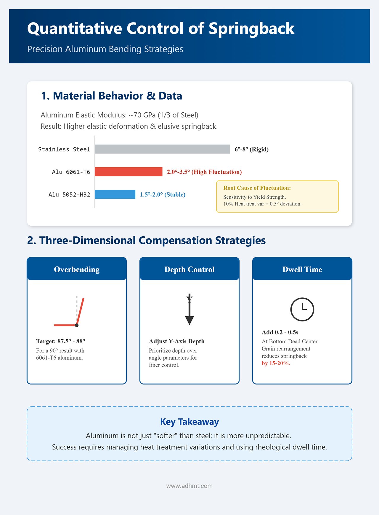
Aluminum’s elastic modulus (around 70 GPa) is only one-third that of steel, meaning it exhibits significantly greater elastic deformation under the same stress. Its springback behavior is not as “rigid” as stainless steel (6°–8°), but it is far more elusive and difficult to predict.
- Nonlinear Fluctuation of Springback Data
- 5052-H32: Springback is relatively stable, typically 1.5°–2.0°.
- 6061-T6: Springback varies widely, roughly 2.0°–3.5°.
- Root Cause of Fluctuation: Aluminum is extremely sensitive to variations in yield strength. A mere 10% inconsistency in T6 heat treatment can shift the yield strength enough to cause a 0.5° deviation in springback. This explains why even material from the same batch may produce inconsistent bend angles.
- Three-Dimensional Compensation Strategies
- Overbending: If the target angle is 90°, for 6061-T6 the die design or CNC program should set the target between 87.5° and 88°.
- Depth Compensation: In CNC systems, prioritize adjusting the Y-axis press depth rather than the die angle parameter. This allows for finer springback control.
- Dwell Time — The Overlooked Technique: Aluminum exhibits strong rheological behavior. By adding a 0.2–0.5 s dwell time at the bottom dead center (BDC), you allow the compressed grains to rearrange and relieve stress. Tests show this small adjustment can reduce springback by 15–20%, significantly improving angular consistency.
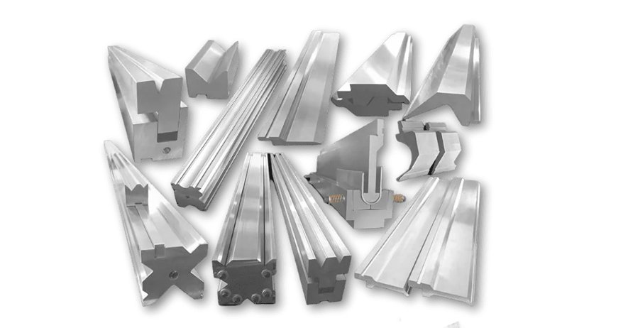
III. Hardware Strategy: Die Material, Coating, and Specialized Configurations
When working with aluminum, clinging to the old steel-processing belief that “the harder the die, the better” is a losing strategy from the very first stroke. The core challenge in aluminum bending isn’t resisting wear—it’s preventing microscopic galling and surface damage.
The hardware strategy is, at its essence, a precise interplay of tribology and geometric compatibility. For more insights into tooling selection, explore press brake tooling basics.
3.1 Die Base Material and Surface Treatment Techniques
For stainless steel, what we need most is compressive strength; for aluminum, the priorities shift to chemical inertness and an ultra-low coefficient of friction. Using conventional 42CrMo (SCM440) steel dies—even after heat treatment—for aluminum bending is a risky move.
Under the intense contact pressure of bending, aluminum atoms become thermally activated and migrate into the steel substrate, forming visible “pickups.” Once these aluminum buildups are cold-welded onto the die’s shoulder, they act like serrated blades, scratching every subsequent workpiece.
- Base Material Upgrade: Beyond 42CrMo For high-spec aluminum components, it’s advisable to upgrade to DC53 or D2 cold-work tool steel. The goal isn’t just higher hardness—it’s a denser and more uniform microstructure. DC53, in particular, features finely dispersed carbides, allowing mirror-grade polishability (low surface roughness, Ra) and physically minimizing adhesion points for aluminum particles. You can learn more about suitable press brake die material for aluminum applications.
- Coating Revolution: The TiCN Trap vs. the DLC Salvation
- ❌ Avoid TiCN (Titanium Carbonitride): A gold-standard coating for carbon steels, but a fatal mismatch for aluminum. Titanium and aluminum have strong chemical affinity, easily forming adhesive bonds under heat and pressure.
- ✅ The Ultimate Solution—DLC (Diamond-Like Carbon): The “holy grail” for aluminum bending. DLC coatings offer an exceptionally low friction coefficient (about 0.05–0.1, close to Teflon) and extreme chemical inertness, completely blocking atomic diffusion between aluminum and steel. This allows aluminum to glide smoothly across the die surface, behaving more like a fluid than a solid under friction.
- ⚖️ Cost-Effective Alternative—CrN (Chromium Nitride): When DLC is beyond budget, CrN offers the best balance. It provides far better anti-galling performance than TiN-based coatings while keeping costs manageable.
3.2 Specialized Solutions for Scratch-Free Bending
When working with anodized aluminum sheets or Class-A automotive interior panels, “scratch-free” isn’t optional—it’s mandatory. Here, sliding friction arises from the relative motion between the die shoulder and the sheet surface. The only way to eliminate scratches is to alter the friction mechanism or introduce a protective medium.
Urethane Protective Film: The Low-Cost Defense Line This is the quickest and most effective tactic—place a protective urethane film on the lower die to isolate metal-to-metal contact. For additional guidance, download detailed brochures from ADH for advanced film options.
- 🚀 Pro Tip: Never use cheap 0.1 mm films—they’ll tear instantly when bending hard alloys like 6061. Always choose 0.4–0.6 mm high-performance urethane films.
- ⚠️ Parameter Compensation: Adding film effectively narrows the V-opening and increases the bend radius. Empirically, you’ll need to deepen the ram stroke (Y-axis) by 0.1–0.2 mm to offset the angular deviation caused by the film thickness.
Wing Bend / Rotary Dies: A Physics-Level Game Changer This is the ultimate mechanical solution for eliminating press marks. Traditional V-dies rely on sliding friction, whereas rotary dies use rotating arms that “cradle” the sheet during bending.
💎 Core Advantage: They convert sliding friction into rolling friction. Since there’s no relative motion at the contact point, you can theoretically achieve zero surface scratches. Additionally, rotary dies prevent hole distortion when bends are close to perforations—something conventional V-dies can’t manage.
Urethane Pad Dies: Isotropic Flexible Forming Replace the lower die with a high-hardness urethane block to achieve pressure distribution similar to hydraulic forming. This method works especially well for large-radius bends and irregular profiles, offering excellent surface protection. The trade-offs, however, are shorter die life and less predictable springback control.
3.3 Die Configuration for Complex Cross-Sections
Bending aluminum extrusions or complex sheet-metal profiles is often constrained by the geometry of the part itself. Aluminum’s high springback tendency amplifies these interference risks.
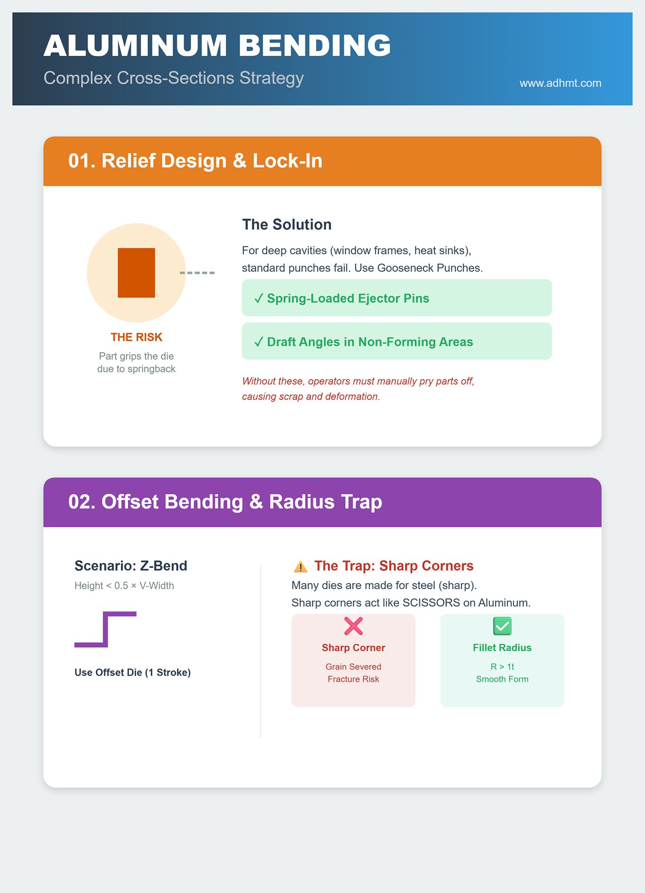
- Relief Design and the “Lock-In” Risk Standard straight punches can’t access deep or recessed cavities (such as window frames or heat sink housings), necessitating gooseneck or sash punches.
- 🛠️ Critical Detail: Due to aluminum’s strong springback, parts may tightly grip the upper die after bending. When designing custom gooseneck tools, ensure sufficient draft angles in non-forming areas and consider adding spring-loaded ejector pins. Without these, operators will have to pry off each part manually, risking deformation and scrap.
- Z-Bend (Offset Bending) and the Radius Trap When forming Z-shaped steps, if the height difference is less than half the V-width, the bend can’t be completed in two passes—use an offset die to form it in one stroke.
- ⚠️ Aluminum-Specific Note: Many commercial offset dies are designed for steel with sharp internal corners. For aluminum (especially 5052-H32 and harder), the offset step must include a fillet radius (R > 1t). Sharp-cornered offset dies act like scissors, severing the aluminum’s grain structure and causing immediate fracture. To understand how different metals behave, see can press brakes bend aluminum.
IV. Process in Practice: From Setup to First Article Approval
Setting theoretical parameters is only the opening move—the real victory lies in translating those numbers into precise machine movements.
Aluminum bending behaves fundamentally differently from steel, demanding a more delicate “feel” and a deeper understanding of the press brake’s dynamic behavior. For precision press brake machinery, consider ADH Machine Tool solutions designed for aluminum applications.
This chapter covers tonnage control, defect prevention, and tooling details to recreate a true high-standard aluminum bending environment.
4.1 Tonnage Calculation and Equipment Matching
Don’t let aluminum’s softness fool you—that’s a dangerous misconception. Although its tensile strength is only about one-third to one-half that of steel, underestimating it can lead to equipment damage or scrapped parts. Aluminum bending typically uses wider V-openings than steel, and this geometric change makes tonnage requirements counterintuitive.
- The “Aluminum Correction Factor” in Tonnage Calculations The standard air-bending formula, ( P = 650 × S² × L / V ), is based on low-carbon steel with a tensile strength of (450 N/mm^2). For aluminum, you must apply correction factors rather than copying steel reference tables:
- 5052-H32 (Soft Aluminum): Correction factor ≈ 0.5, meaning only about 50% of the theoretical tonnage required for steel.
- 6061-T6 (Hard Aluminum): Correction factor ≈ 0.6. Though its strength approaches certain steels, its high springback demands greater holding force—don’t underestimate it.
⚠️ High-Risk Alert: Hemming (Flattening) Operations
During hemming operations, the required tonnage can instantly spike to four to five times that of air bending.
Remember: hemming aluminum is far riskier than hemming steel. Steel exhibits good plastic flow and will naturally spread sideways under pressure. In contrast, hard aluminum alloys (such as 6061) lack this ductility and tend to crack or even burst the moment they are flattened. Operators must wear protective eyewear and carefully control the press limit to prevent tool overload and fracture.
- Machine Dynamics: Taming “Overshoot” Hydraulic press brakes switch from “fast approach” to “work speed” just before contacting the material. When bending steel, the sheet’s reaction force naturally acts as a brake. Aluminum, however, is much softer and produces minimal resistance, making the hydraulic cylinders prone to inertia-driven overshoot.
- 🛠️ Operational Rule of Thumb: In the CNC system, set the Speed Change Point / Mute Point higher than for steel (i.e., start decelerating farther from the sheet). This ensures the punch enters a slow pressing mode before contact, preventing over-bending on the first part and avoiding high-speed impact marks that are nearly impossible to remove from aluminum surfaces.
4.2 Process Guidelines to Prevent Common Defects
In aluminum bending, defects often stem not from dimensional inaccuracies but from compromised appearance or microstructural damage. The following are specialized countermeasures for three persistent issues:
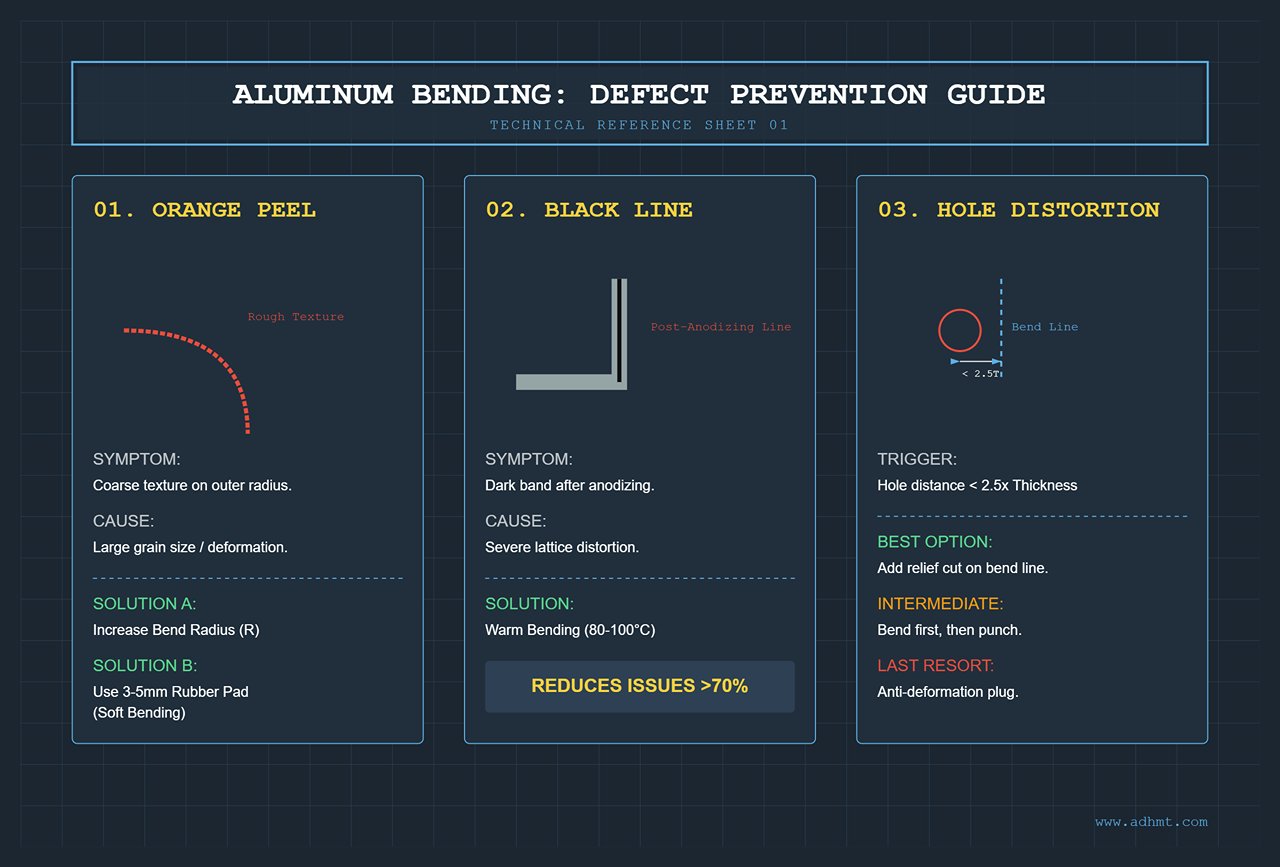
- Defect 1: Orange Peel on Bend Outer Surface
- Symptom Diagnosis: A coarse texture resembling orange skin appears on the outer bend radius. This indicates macroscopic slip between grains, typically caused by large grain size or excessive localized deformation.
- Practical Countermeasures:
- Geometric Dispersion: This is essentially a material issue. If fine-grain sheet cannot be sourced, the only process-based remedy is to increase the bend radius (R).
- Soft Bending Technique: If a large-radius punch is unavailable, place a high-hardness rubber pad (3–5 mm) between the die and the workpiece. The elastic medium helps distribute surface tension, sacrificing some angle precision but often saving the finish — the last resort for aesthetic recovery.
- Defect 2: “Black Line” after Anodizing
- Symptom Diagnosis: The raw part appears flawless, but after anodizing, a dark band emerges along the bend line. This occurs because severe lattice distortion in the bend area alters oxidation kinetics, producing a visibly different oxide film.
- Confidential Solution: Warm Bending Before bending, preheat the bend line with an industrial hot-air gun to 80–100°C (hot to the touch but not burning). This modest thermal input activates lattice mobility and eases internal stresses from work hardening. Field data show that warm bending can reduce post-anodizing black-line issues by over 70%, making it a closely guarded secret in high-end aluminum panel fabrication.
- Defect 3: Hole Distortion near Bend Line
- Physical Limit: When the edge distance from the hole to the bend line ( L < 2.5t ) (where t is sheet thickness), deformation becomes unavoidable.
- Remediation Strategies:
- Best Option (Design Optimization): Add a relief cut along the bend line to interrupt the stress path. This is the smartest and most cost-effective solution.
- Intermediate Option (Process Adjustment): Perform bending first, then punch or drill the hole. This requires specialized side-punch tooling or an additional CNC operation.
- Last Resort (Manual Correction): Insert a custom anti-deformation plug into the hole. Labor-intensive and time-consuming, this method is only suitable for small-batch recovery.
4.3 Specialized Tooling and Fixtures for Aluminum
Aluminum is not only sensitive to bending but even more vulnerable to clamping and abrasion. Its surface hardness is far lower than that of a press brake’s worktable—any rough contact can leave irreversible scratches.
- Demagnetized Positioning System Magnetic backgauges commonly used for steel sheets are ineffective with aluminum.
- Gripping Solution: Upgrade backgauge fingers to pneumatic vacuum cups or spring-loaded mechanical fingers. This not only ensures precise positioning but also prevents operators from accidentally denting edges during manual alignment.
- “Soft Landing” on Worktable Surface The cast-iron or steel support arms of a press brake are major culprits behind scratched aluminum sheets. Even a tiny steel chip can ruin an expensive brushed panel as it slides.
- 🛠️ On-site modification: Shield the support arms with protective coverings.
- Brush Surface: Install industrial nylon brush strips on the support racks to let aluminum sheets glide freely.
- Teflon Tape: The most economical fix—wrap all metal-to-aluminum contact areas with PTFE (Teflon) tape.
- 🛠️ On-site modification: Shield the support arms with protective coverings.
Remember: in aluminum processing, a flawless surface is itself a mark of high precision. For expert consultation or tailored tooling solutions, feel free to contact us.
V. Fault Diagnosis and Maintenance: Full Life-Cycle Management
As press brakes operate day after day, engineers often shift focus away from parameter tuning, overlooking a hidden adversary on the production floor—progressive failure. In aluminum forming, the failure mechanism differs completely from steel: steel wears the die, while aluminum builds up on it.
This unique degradation pattern demands a distinct diagnostic and maintenance framework that moves quality assurance from reactive correction to proactive prevention.
5.1 Root Cause Analysis (RCA) of Typical Failure Modes
In aluminum bending operations, 90% of sudden quality incidents stem not from machine malfunction but from neglecting micro-level changes in die condition. Below is the root cause analysis for three aluminum-specific failure modes:
1. Galling / Pickup: More Than Just a “Dirty Tool”
This is the number-one killer in aluminum bending. You may notice white specks on the die shoulder of the V-groove, or irregular scratches on the workpiece surface.
- Physical Appearance: White aluminum deposits adhere to the die surface and resist cleaning.
- Root Cause: This is not mere adhesion—it’s cold welding. Under high contact pressure, the aluminum’s oxide layer fractures, exposing highly reactive aluminum atoms that bond directly with the die’s iron substrate. The frictional heat accelerates this atomic-level fusion.
- Common Misdiagnosis: Many operators assume the die isn’t hard enough. In fact, galling arises from material affinity, not hardness. Even the hardest uncoated tool steel cannot eliminate the chemical attraction between aluminum and iron.
- Failure Consequence: Once built-up edge (BUE) forms, the friction coefficient on the die surface surges instantly, causing bending angle deviations. The BUE then acts like sandpaper, scratching every subsequent workpiece.
2. Angle Drift: The Illusion of Shoulder Wear
After producing thousands of parts continuously, the bending angle begins to fluctuate unpredictably. Even resetting the back gauge fails to resolve the issue.
- Root Cause: The culprit isn’t a malfunctioning hydraulic system, but microscopic changes in the V-die’s shoulder radius.
- Scenario A (Radius Increases): The aluminum oxide layer (Al₂O₃) on the material surface is extremely hard (Mohs hardness 9). Prolonged friction gradually wears down the die shoulder radius, enlarging it. The sheet then sinks deeper into the V opening, resulting in a smaller bend angle.
- Scenario B (Radius Decreases): Accumulated BUE on the shoulder reduces the effective V-width, producing a larger bend angle.
- Diagnostic Method: Don’t measure only the workpiece—measure the die itself. Use a radius gauge regularly to check for consistency in the lower die shoulder radius.
3. Center Dishing: Damage Caused by Operator “Laziness”
The bent part shows a “canoe effect”—a larger angle in the middle and smaller angles at both ends.
- Root Cause: Operators habitually place short workpieces only at the center of the press brake for convenience.
- Mechanism: Although aluminum requires relatively low bending force, long-term localized loading causes plastic deformation or fatigue wear at the center of the die, while both ends remain untouched.
- Warning: For aluminum, which is extremely sensitive to precision, a die unevenness of just 0.02 mm can result in a bending angle deviation of 0.5°.
5.2 Die Life Extension and Maintenance Standards

To maintain die accuracy in aluminum processing’s harsh environment—characterized by abrasive aluminum oxide and adhesive aluminum dust—you must follow a specialized, non-ferrous maintenance protocol.
1. Cleaning Taboos: Ditch the File!
In factories processing steel sheets, operators often use an oilstone or fine file to remove iron debris from dies. In aluminum bending, this is absolutely fatal.
- Prohibited Actions: Never use any metal removal tools (files, steel scrapers) or coarse sandpaper to clean dies. Doing so destroys the die’s polished surface, creating micro-pits that become “anchoring points” for the next BUE formation.
- Proper Procedure:
- Light Aluminum Build-Up: Wipe with Scotch-Brite pads moistened with industrial alcohol or mold cleaner.
- Heavy Aluminum Build-Up: Apply sodium hydroxide (NaOH) solution locally to dissolve aluminum deposits (handle carefully to avoid corroding the steel base), or use a copper scraper, which is softer than steel.
- Coated Dies: For DLC or TiCN-coated dies, only a soft cloth may be used. Any abrasive action can strip off the expensive coating.
2. Lubrication Strategy: Replace Friction with Film
Although modern sheet metal processing favors dry operations, a moderate amount of lubrication is essential for problematic aluminum alloys (such as 5052 soft aluminum) to extend die life.
- Practical Tip: Use volatile stamping oil or dry lubricant spray.
- After every 50–100 bends, spray the lower die shoulders once. This reduces friction, prevents BUE formation, and—most importantly—creates a micron-thin physical barrier between aluminum and steel.
- Note: Avoid viscous machine oil, which traps aluminum dust and forms an abrasive paste that accelerates wear.
3. Rethinking Usage: Load Balancing
Don’t let the center section of the die bear all the load alone.
- Operational SOP: Establish a strict workstation rotation schedule.
- When bending small aluminum pieces, instruct operators to alternate between the left, center, and right sections of the press brake.
- Advanced CNC systems (such as the Delem DA-60 series) now feature a “workstation guidance” function that prompts operators on-screen: “Next bend: operate on the left station.” This ensures uniform wear and can extend die life by over threefold.
4. Storage Environment: Moisture Control Prevents Adhesion
Aluminum dust is not only flammable but also highly hygroscopic.
- Storage Rule: After bending, immediately remove aluminum dust from the die. Aluminum dust strongly absorbs moisture, and once wet, it triggers galvanic corrosion that etches microscopic pores into the steel surface.
- Sealing Standard: After use → clean aluminum dust → spray anti-rust oil → store in a drying cabinet. For high-precision aluminum dies, physically separate them from carbon steel dies to prevent cross-contamination.
🚀 Expert Insight: A die is a living tool. In aluminum processing, its surface finish is its lifeline. The moment you take sandpaper to a die for convenience, you unleash the Pandora’s box of BUE formation—entering a destructive cycle of “polish–stick–repolish” until the die is ruined. Maintenance, at its core, is about protecting that mirror finish.
VI. Next Level and Beyond: Digitalization and Intelligent Tool Selection
In traditional sheet metal shops, die selection often comes with heavy “trial-and-error” costs—cutting test strips, setting up tooling, scrapping several aluminum sheets—only to find springback or interference issues.
In the Industry 4.0 era, the selection process for high-springback, scratch-prone materials like aluminum is undergoing a profound shift—from experience-based decisions to digital twin-driven precision.
6.1 Application of Digital Tool Selection Systems: From Trial to Simulation
Die selection today is far beyond flipping through paper catalogs. The widespread adoption of Digital Twin technology allows 99% of verification to occur virtually, driving physical trial costs nearly to zero.
- Deep Integration of 3D Bending Simulation Software: Don’t rely solely on 2D drawings to judge die compatibility. For complex aluminum parts such as electronic enclosures or aerospace brackets, collision risk is the biggest hidden danger in die selection.
⚠️ Real-World Pain Point: Many engineers correctly calculate and choose a V12 die, but during the fourth bend of an aluminum box (usually the final closure), the sidewall collides directly with the punch holder, invalidating the entire setup.
🚀 Solution: Use simulation tools like AutoPol, BySoft, or SolidWorks Sheet Metal to request that suppliers provide STEP-format 3D models of the dies before purchase. Run a full virtual bending simulation—you may discover that instead of a standard straight punch, you actually need a gooseneck or sash punch to avoid interference. This single “rehearsal” can save tens of thousands in misprocurement costs.
- Integration of Cloud-Based Tooling Libraries and Material Big Data
Leading manufacturers such as WILA and Trumpf have established extensive cloud-based selection systems. The real value of these systems lies not in merely displaying geometric parameters but in their vast aluminum material physics databases that power data-driven decision-making.
💎 Data Empowerment: When you input “6061-T6, thickness 3.0 mm, bend angle 90°,” the cloud algorithm doesn’t just recommend a suitable V-die opening. It also references historical performance data to inform you, for instance, that “this material typically exhibits a springback of about 2.8° when bent with a V24 die.” The system then automatically generates a corrected DXF drawing or even exports the ready-to-run CNC program. This kind of data-driven precision far outperforms the traditional workshop estimate of “roughly 2 degrees of springback.”
6.2 Industry Outlook: AI and Adaptive Bending
While we still struggle with aluminum’s unpredictable springback, cutting-edge bending machines have evolved to “think” and “self-correct.” In the near future, tooling selection will no longer be a mere hardware purchase but a fully integrated software–hardware intelligence process.
- Adaptive Springback Control System
This is the ultimate weapon against inconsistencies between aluminum batches. Intelligent press brakes equipped with Lazer Safe laser angle sensors or contact probes are redefining the rules of precision bending.- Closed-Loop Operation: During bending, the machine continuously measures the sheet angle. For example, with a target of 90°, it first bends to 88° for detection. If it identifies that a batch of 5052 aluminum is softer and springs back only 1.5° (actual 89.5°), the system instantly calculates the deviation and automatically adjusts the ram pressure by microns to achieve an exact 90° bend.
- Why It Matters for Aluminum: Aluminum’s yield strength fluctuates widely—even between batches from the same supplier, springback can vary by more than 0.5°. With adaptive systems, there’s no need to re-test tooling parameters for every batch. The machine ensures “first-piece accuracy,” enabling seamless one-piece flow production.
- Tooling “Identity ID” and Lifecycle Management
In the near future, every die segment will carry a Data Matrix code or embedded RFID chip, marking the beginning of fully digital hardware traceability.- Error-Proofing Mechanism: When an operator mounts a die, the system automatically scans and verifies it. If the program requires a V16 die but a V12 is mistakenly installed, the system will lock operation and trigger an alarm. This function is critical in aluminum processing—using too small a V-opening on thick aluminum can fracture the die and cause serious injury.
- Lifecycle Tracking: The system automatically logs the bending count for each die segment. Given aluminum’s tendency to cause galling, it can issue alerts such as: “This die has bent aluminum 20,000 times—maintenance and polishing recommended.” Such predictive maintenance prevents costly surface scratching incidents caused by aluminum buildup on the die surface.
VII. Decision Checklist: Your Action Roadmap
After analyzing aluminum’s physical properties, key algorithms, and hardware strategies, we return to the core question on the shop floor: What should I decide right now?
Before signing the tooling purchase order or releasing the process sheet, this decision checklist serves as your final safeguard. It’s not just a set of “recommendations”—it’s a collection of hard-earned survival rules distilled from countless aluminum bending failures.
7.1 Tooling Selection Decision Matrix (Checklist)
Before placing a tooling order or finalizing your process route, use this matrix to conduct a rigorous self-assessment. Overlooking even a single criterion could turn an expensive die into scrap metal—or worse, trap your project in endless delivery delays.
| Dimension | Checkpoints | Aluminum-Specific Criteria (Pass/Fail) |
|---|---|---|
| Material | Alloy temper verification | ⚠️ Critical rule: Confirm whether the material is T6 (hard/brittle) or O/H32 (soft/ductile). ❌ If the drawing specifies 6061-T6 and the inner radius R < 3t, reject the job or request a design change immediately. Never rely on luck. |
| Batch consistency | ⚠️ Do you have yield strength test data from the previous batch? ✅ If not, allocate twice the normal steel setup scrap for first-piece trials. | |
| Geometry | Minimum radius compliance | ✅ Is the punch tip radius ≥ sheet thickness (for 6061)? ✅ Check for hole-to-edge distances < 2.5t—if present, prepare anti-deformation fixtures in advance. |
| Interference alert | ✅ For U-shaped bends, is the height-to-width ratio > 1.5? ⚠️ If > 2.0, standard gooseneck punches will likely interfere—order a deep sash punch instead. | |
| Surface | “A-side” appearance requirements | ⚠️ Are minor surface marks acceptable? ❌ No → Use Wing Bend tooling or 0.6 mm polyurethane film. ✅ Yes → Use large-radius punches with polished dies. |
| Production Volume | Tool life & coating | ✅ For orders > 5,000 pcs → DLC coating is mandatory—any cost-cutting here is false economy. ✅ For orders < 100 pcs → Standard 42CrMo dies with 0.5 mm protective film are acceptable for short runs. |
7.2 ROI Insight: Accounting for Hidden Costs
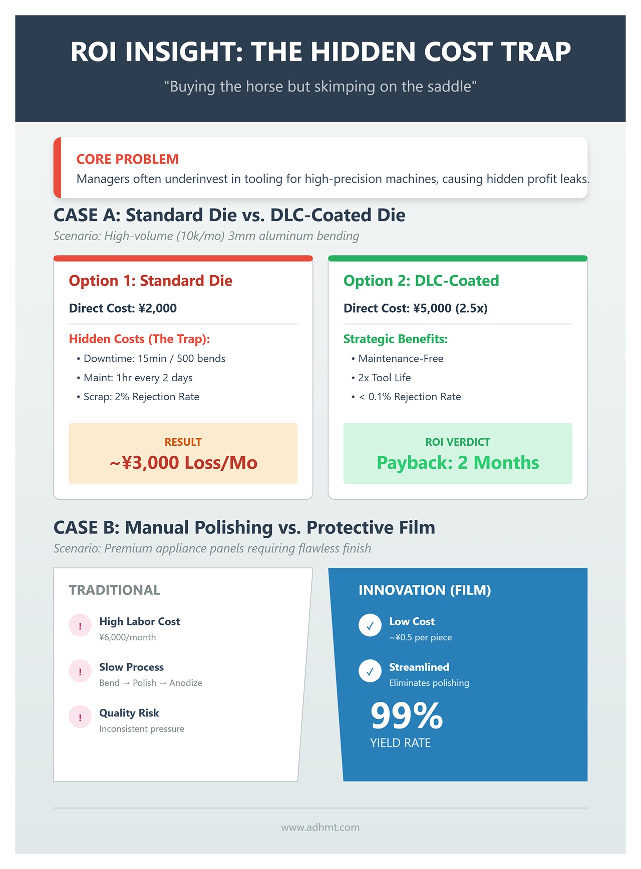
Many plant managers fall into a common trap: they’ll spend ¥2 million on a high-precision press brake but hesitate to pay an extra ¥20,000 for a die truly optimized for aluminum. This “buying the horse but skimping on the saddle” mindset is a hidden drain on productivity and profit.
Here are two real-world ROI case studies to help you persuade decision-makers using financial reasoning:
Case A: Standard Die vs. DLC-Coated Die
- Scenario: Bending 3 mm 6061 aluminum sheet, monthly output 10,000 pcs, high risk of galling.
- Option 1: Standard Die (42CrMo)
- Direct Cost: ¥2,000 per segment.
- Hidden Costs:
- Downtime cleaning: Every 500 bends, stop for aluminum chip removal (15 minutes).
- Maintenance: Full polishing required every 2 days (1 hour downtime).
- Scrap Losses: Surface scratches from aluminum chips result in an approximate 2% rejection rate.
- Estimated Monthly Loss: Downtime labor cost plus scrap material ≈ ¥3,000 per month.
- Option 2: DLC-Coated Mold
- Direct Cost: ¥5,000 per unit (about 2.5 times the price of a standard mold).
- Hidden Benefits:
- Maintenance-Free: The ultra-low friction coefficient prevents aluminum buildup.
- Extended Lifespan: Surface hardness is significantly increased, effectively doubling tool life.
- Quality Gains: Scratch-related rejection rate drops below 0.1%.
- ROI Summary: Payback in 2 months. For high-volume aluminum production, skipping DLC coating is like letting profits “leak” every quarter.
Case B: Manual Polishing vs. Polyurethane Protective Film
- Context: Premium aluminum alloy panels for high-end appliances, requiring flawless A-surface finishes.
- Option 1: Traditional Approach (Post-bend Manual Polishing)
- Process Flow: Bending → Surface scratches → Manual grinding and polishing → Anodizing.
- Cost Pain Points: Requires one full-time polishing worker (labor cost ¥6,000/month). Inconsistent polishing pressure causes noticeable color variation after anodizing, leading to frequent rework.
- Option 2: New Approach (Using 0.6mm Polyurethane Protective Film)
- Direct Cost: Material cost around ¥0.5 per piece.
- Process Innovation: Eliminates the polishing step entirely—bending produces a finished part.
- Quality Gains: Yield rate soars to 99%, with perfectly consistent surface texture.
- ROI Summary: A true “dimensionality reduction strike.” For appearance-critical components, protective film isn’t a cost—it’s a money-saving machine, replacing expensive manual labor and quality risks with a low-cost consumable.


