Press brake laser safety is no longer just a compliance checkbox; it is the technical and economic hinge between high-risk legacy bending and intelligent, high‑throughput production. Modern laser-based AOPD systems allow near‑tool guarding at finger resolution while maintaining cycle times that traditional fences and light curtains could never achieve.
This article reframes safety as an asset, unpacking the physics and control logic behind laser safeguards, showing how to retrofit old presses, run them reliably on the shop floor, and ultimately plug them into AI‑driven, data‑centric smart bending workflows.
I. Core Cognitive Shift: Breaking the Old Paradox of “Safety vs. Efficiency”
In the sheet metal fabrication industry, a frustrating paradox has long persisted: to ensure safety, efficiency must be sacrificed; yet to meet production deadlines, safety systems are often bypassed.
With the evolution of laser safety technology, however, this zero-sum game has finally been overturned. Modern press brake safety systems are no longer just a shield protecting operators—they have become accelerators that enhance overall equipment effectiveness (OEE).
1.1 Pain Point Analysis: The Hidden Killers and Efficiency Bottlenecks in the Bending Workshop
Press brakes, with their massive tonnage and open operation zones, have consistently topped accident statistics in the metalworking industry.
- The Dual Threat of Pinch Points and Whip-up Traditional safety awareness often focuses solely on the pinch point hazard caused by the descending ram. Yet seasoned operators know that workpiece whip-up is an even stealthier killer. When high-strength sheet metal snaps upward at high speed during bending—or fractures due to brittleness—it can strike the operator’s face or chest with tremendous force. This physical danger triggers a psychological defense mechanism: operators move more slowly and double-check repeatedly to protect themselves. Such fear-induced hesitation silently erodes productivity. According to the U.S. Department of Labor, nearly half of all press brake accidents result in amputations, with compensation costs often reaching hundreds of thousands of dollars—enough to cripple the cash flow of a small or mid-sized manufacturer. To learn more about effective preventive measures, see optical safety arrangements that can mitigate these risks.
- The “Stop-and-Go” Dilemma of Traditional Safeguards For decades, infrared light curtains have been the mainstream protection method. However, according to the safety distance formula (D_s = K × T_s + D_pf), the light curtain must be installed at a considerable distance from the die. This creates the notorious Stop-and-Go phenomenon:
- The ram descends rapidly.
- Well before reaching the workpiece (typically more than 6mm away), the system is forced to switch to slow speed to prevent finger intrusion.
- During every bending cycle, the operator must endure several seconds of unproductive waiting.
On production lines performing thousands of bends per day, the cumulative time loss caused by this technical limitation translates into a staggering waste of potential output. To explore how to overcome such limitations, check out ADH Machine Tool, a leader in intelligent bending technology.
1.2 The Evolution of Technology: From Passive Barriers to Active Intelligence
If mechanical fences are like cages keeping people out, and infrared light curtains are invisible walls, then the Laser Safety System (LSS)—especially the Active Optoelectronic Protective Device (AOPD)—gives machines both “eyesight” and “intelligence.”
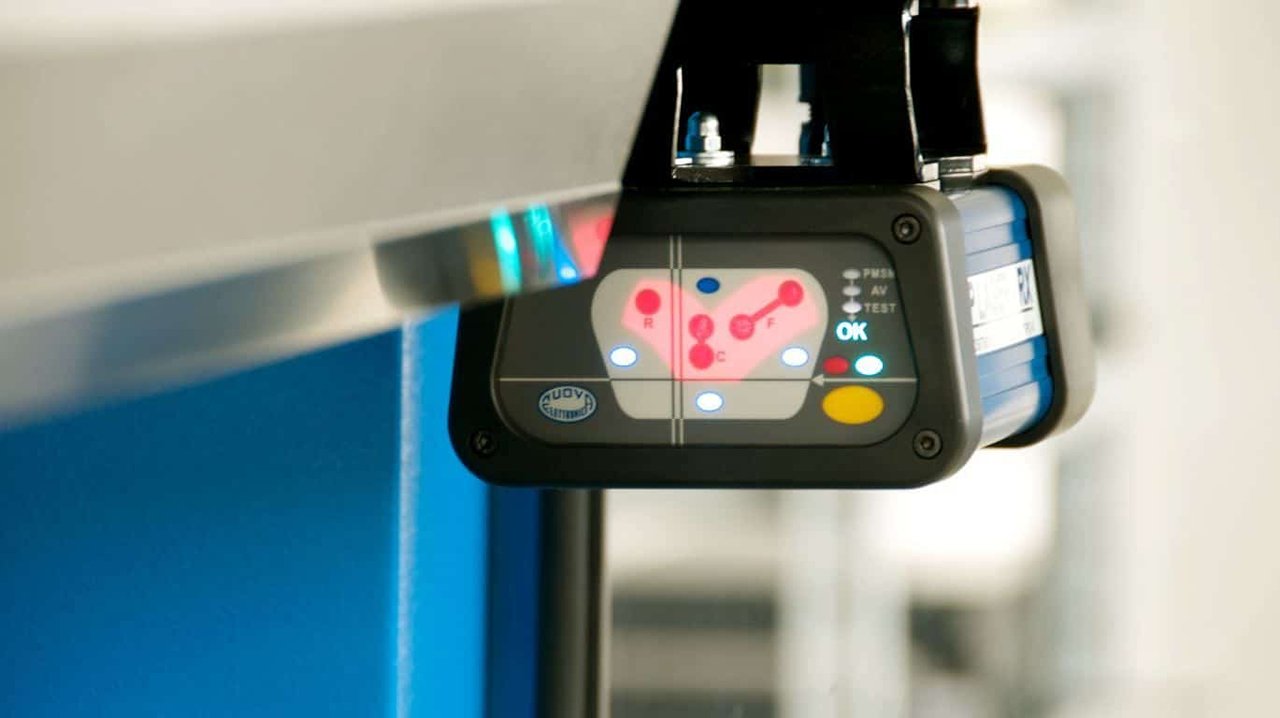
- From Static Defense to a Moving Bodyguard The new generation of laser safety systems (from brands such as Lazer Safe and Fiessler) employ dynamic tracking technology. The laser emitter and receiver are mounted on the upper beam, with the light field moving in perfect sync with the punch tip.
- Millimeter-Level Precision: Modern AOPDs now offer resolution better than 14mm, capable of detecting even fingertip intrusion with high accuracy.
- Intelligent Object Recognition: Advanced algorithms distinguish between a “sheet bending upward” and a “foreign object entering the danger zone.” This enables the system to automatically mask certain beams (Box Mode/Tray Mode) when forming box or irregular parts, eliminating false stops common with light curtains and solving long-standing issues in side-wall bending.
- The ‘2mm’ Efficiency Breakthrough This is the most revolutionary aspect of laser safety technology. Thanks to ultra-fast response times and seamless CNC integration, the laser AOPD allows the ram to descend at full speed until just 2mm above the workpiece before switching to forming speed (the Mute Point). In contrast, traditional light curtains require deceleration tens of millimeters earlier. This 2mm transition threshold drastically shortens the slow travel distance. The resulting “fast descent—instant stop—smooth pressing” sequence achieves both ISO 13849 PL e / Cat. 4 safety compliance and peak mechanical efficiency. If you want to learn more about system fine-tuning, see how to adjust the dsp laser protection for press brake.
1.3 Strategic Value: Why Upgrading to Laser Protection Is Now Imperative
For decision-makers, upgrading to a laser safety system should not be viewed as a mere safety expense—it is a high-return capital investment.
- ROI: Converting Seconds into Profit Let’s run the numbers: adopting an advanced laser protection system (such as those featuring RapidBend technology) can save 2 seconds per bending cycle. If a machine performs 1,000 bends per day, that’s roughly 33 minutes saved daily, or 137 hours annually (based on 250 working days). That’s equivalent to gaining an entire month of a skilled operator’s productivity—at zero labor cost. The resulting improvement in OEE often pays back the upgrade cost within 12 to 18 months. You can find detailed specifications and ROI data in our brochures.
- Solving the Skilled Labor Shortage Through Technology In an era of acute shortages of experienced sheet metal operators, laser safety systems reduce dependence on operator skill. The system allows operators to hold the workpiece close to the die throughout the ram’s descent—without risk of injury. This “zero-distance safety” boosts operator confidence, shortens training time, and significantly reduces scrap rates caused by handling errors.
- Compliance as a Non-Negotiable Baseline With updates to ANSI B11.3 and ISO 13849, safety regulations now impose stricter requirements for control reliability. Many legacy machines retrofitted with simple single-channel light curtains no longer meet the standards for fault self-diagnostics. In the event of an accident, companies face not only heavy fines but also possible denial of insurance claims on the grounds of noncompliance. Upgrading to a certified laser system is the only reliable way to mitigate such systemic legal risks. For professional consultation on compliance and system upgrades, feel free to contact us.
II. Deep Technical Insights: The High-Tech Core of the Laser Safety System (LSS)
If traditional light curtains are the press brake’s “crash barriers,” then the modern Laser Safety System (LSS) is its “optic nerve.” It no longer operates on simple open/close logic; instead, it leverages complex optical geometry and real-time algorithms to distinguish process-related movements from true hazards within milliseconds.
2.1 Optical Geometry and Detection Logic: From a ‘Blind Wall’ to an ‘Intelligent Eye’
Traditional infrared light curtains create a static vertical light wall, whereas the core innovation of laser AOPDs lies in their traveling field and multi-zone detection architecture.
- Constructing the Moving Protection Field: The emitter and receiver are rigidly mounted on either side of the upper ram, moving synchronously with the tooling. The system forms a tightly focused “protective envelope” just below the punch tip—typically divided into front, center, and rear zones. This design ensures that the protection field always remains a few milliseconds ahead of potential pinch points, eliminating the blind spots inherent in fixed light curtain installations.
- Dynamic Muting Algorithm Logic: This is what fundamentally distinguishes an LSS from low-end photoelectric switches. The system monitors the ram’s position, speed, and time in three dimensions to determine the nature of any “intrusion.”
- Foreign Object Detection: If the light beam is interrupted while the ram is moving downward at high speed (greater than 10 mm/s), the system interprets it as a finger or foreign object and immediately triggers an emergency stop (E‑Stop).
- Normal Working Stroke: When the ram slows to a safe speed (typically ≤ 10 mm/s) and reaches the mute point approximately 2 mm above the sheet surface, the system automatically disables detection in the front and rear zones, keeping only the middle zone active—or fully muting the field—to allow the tool to make contact and complete the bend. This seamless transition is the key to achieving true “zero‑pause” operation.
- Box Mode Intelligent Masking: Forming sidewalls, such as during box bending, has long been a safety nightmare that often forces operators to disable protection. Advanced LSS systems solve this through programmable masking. When a sidewall blocks the front or rear light beams, the system does not trigger an emergency stop; instead, it temporarily masks the affected beam area according to the pre‑set “flange height” logic, keeping only the zone directly beneath the punch tip active. This allows the press brake to maintain full‑speed operation even when processing complex or irregular parts—without any manual intervention. For more insights into this optical principle, refer to optical safety arrangements.
2.2 Core Performance Metrics and Selection Criteria: Safety Defined by Data
When selecting or evaluating an LSS, brand reputation alone is not enough. You must dig into the granular technical parameters and focus on the following decisive indicators:
- Safety Integrity Certification: Compliance with ISO 13849‑1 PL e (Performance Level e) and Category 4 is mandatory. This means the system must feature dual‑channel monitoring and an exceptionally high level of diagnostic coverage. In simple terms, even if a single internal component fails—such as a relay sticking—the safety function remains intact and the system will self‑diagnose and issue an error. For press brakes involving human safety, PL d or lower is an unacceptable red line.
- Stopping Time ((Ts)) and Safety Distance: These are governed by hard physical constraints. The total stopping time is calculated as T_s = T_response + T_valve + T_inertial, that is, signal response time + hydraulic valve closure time + ram inertia stop time. A high‑quality LSS should achieve a system response time within 5 ms. Ts directly determines how far ahead of the punch tip the laser field must be positioned. The shorter the Ts, the closer the laser can be placed, allowing the speed change point (SCP) to be set lower—thus improving production efficiency.
- Comparison of Two Technology Approaches:
- Point‑Laser Type: Examples include Lazer Safe Sentinel and Fiessler AKAS.
- Advantages: Extremely fast response, strong interference resistance, ideal for high‑speed, large‑volume production of standard parts.
- Limitations: Requires precise tool alignment and may need adjustment when changing to molds of different widths.
- Vision‑Based Type: For instance, Pilz PSENvip.
- Advantages: Uses cameras to capture the tool and workpiece profiles in real time, suitable for highly complex variable‑section molds or frequent tool changes.
- Limitations: Image processing introduces slightly higher latency than point‑laser systems and is more sensitive to ambient light conditions.
- Point‑Laser Type: Examples include Lazer Safe Sentinel and Fiessler AKAS.
2.3 System Integration Architecture: Not Just a Brake, but a Co‑Pilot
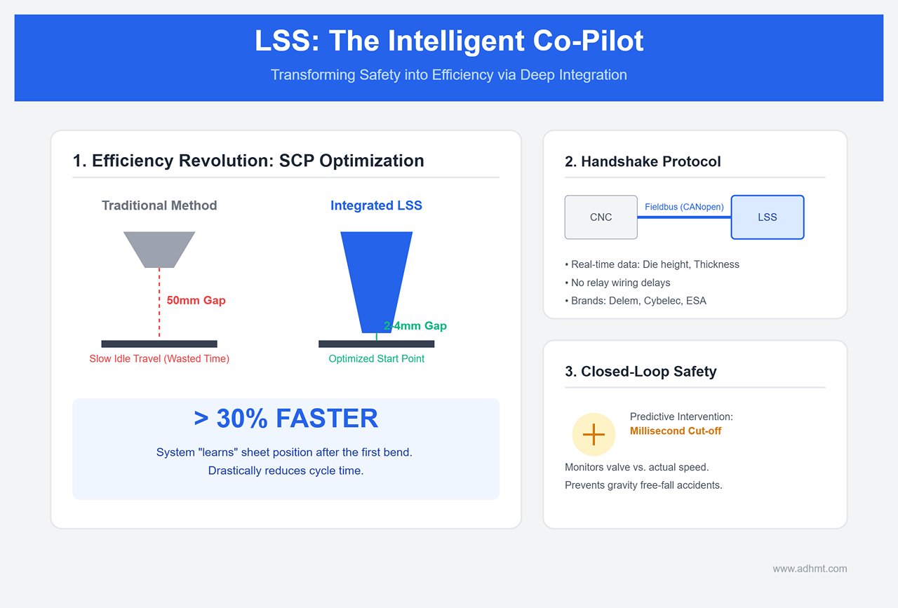
Modern LSS units are no longer external “circuit breakers.” They are deeply integrated into the CNC control loop, forming a closed‑loop control system.
- Handshake Protocol with CNC: High‑end LSS systems communicate directly with CNC controllers (such as Delem, Cybelec, ESA) via fieldbus protocols like CANopen or SafetyBUS. In addition to sending stop commands, the system transmits real‑time data such as die height and sheet thickness. This deep integration eliminates the signal delays inherent in traditional relay wiring, enabling much faster system response.
- Automatic Optimization of the Speed Change Point (SCP): This is the ultimate efficiency booster. In traditional setups, operators often set the fast‑to‑slow transition point about 50 mm above the sheet to simplify operation, wasting significant time in slow idle travel. Integrated LSS systems “learn” the sheet position during the first bend and automatically optimize the SCP to just 2–4 mm above the surface in subsequent cycles. This single feature alone can reduce the bending cycle time by more than 30%.
- Fully Closed‑Loop Monitoring Logic: The LSS continuously monitors the hydraulic proportional valve opening and the actual ram speed. If it detects a mismatch between commanded and actual speed (for example, a free‑fall caused by gravity), the system cuts off the hydraulic circuit within milliseconds. This form of predictive intervention ensures that even in the event of total hydraulic failure, the operator’s fingers remain completely safe.
III. Practical Implementation Guide: Selection, Installation, and Retrofit Projects
Introducing a top‑tier Laser Safety System (LSS) into your workshop is far more than a simple “buy and install” process—it’s a precision operation akin to surgery. For many retrofit projects on older press brakes, the implementation phase determines whether the investment becomes a productivity engine or a source of recurring false alarms. The following guidelines, distilled from frontline engineering experience, are designed to help you avoid hidden pitfalls.
3.1 Pre‑Implementation Site Audit: Avoid Hidden Traps
Before signing any purchase order, the existing equipment must undergo a rigorous “health check.” Many retrofit failures stem not from the laser system itself, but from the machine’s inability to meet the performance demands of modern safety logic.
- The Brake Performance Lifeline (Stop Time & Crawl Speed): Although ISO 13855 and ANSI B11.3 provide the safety distance formula ( S = K \times T + C ), the real challenge during retrofits lies in maintaining stable crawl speed.
- Pitfall: High‑end laser protection systems (such as Fiessler AKAS or Lazer Safe) rely on extremely precise speed feedback. If an older hydraulic system’s proportional valves are worn—causing slow‑stroke speed fluctuations greater than 10 mm/s, or inconsistent stopping times (e.g., variance exceeding 20 ms)—the system will interpret this as a loss of control and trigger repeated emergency stops.
- Countermeasure: A professional stop-time measurement device must be used to perform no fewer than ten consecutive full-load and no-load tests, taking the worst-case result as the calculation basis. If the hydraulic system’s response is too slow (total stopping time >200 ms), priority should be given to replacing the servo drive or hydraulic valve assembly. Otherwise, the only fallback is to use a light curtain system, sacrificing the convenience of close-range operation.
- Eliminating Environmental Interference
- Reflective Surfaces Causing Sensor Blindness: Check whether the workshop frequently processes mirror-finish stainless steel or highly reflective aluminum sheets. Some early single-beam laser sensors can be misled by reflected light from the workpiece surface, causing the receiver to make false readings. When selecting sensors, always confirm they include a polarizing filter or have a built-in anti-reflection algorithm.
- Rigidity and Vibration: For large press brakes exceeding 200 tons, the frame deflection during the stamping moment can cause micrometer-level displacement of the laser emitter fixed on the upper beam. For such heavy-duty machines, assess whether an independent vibration-damping mount is needed or consider using a wide-beam system with higher positional tolerance.
3.2 Standardized Installation and Commissioning: The Devil Is in the Details
True expert-level installation goes far beyond tightening screws and connecting cables—it’s about building a “micron-level parallel universe” that moves in perfect sync with the ram.
- Mechanical Installation: Striving for Zero-Tolerance Parallelism
- Linear Guide Alignment: The linear guide brackets for the emitter and receiver units must be absolutely parallel to the ram’s motion path. Never rely solely on a spirit level. A dial indicator must be mounted on the ram to measure travel across the full stroke of the guide rail.
- Expert Standard: The full-stroke parallelism deviation should be kept within <0.1 mm. Excessive deviation will cause the laser beam to drift during downward motion—working normally at some heights but triggering random stops at others. These intermittent faults are notoriously difficult to diagnose.
- Electrical Integration: Tapping into the “Neural Core”
- Encoder Interface: This is the key to achieving the “2 mm ultra-quiet point.” Do not attempt to control the laser system using only limit switches. The TTL or HTL signals from the linear scales (Y1/Y2) must be split and fed into the laser safety controller (e.g., Lazer Safe Sentinel). Only by capturing the ram’s real-time position and speed can the controller issue the precise “mute” signal within the millisecond window before the punch contacts the sheet.
- Dual-Channel Redundancy (OSSD): Wiring of the safety relays must strictly follow Cat. 4 standards, using dual-channel (OSSD1/OSSD2) logic. Any voltage anomaly in a single channel must trigger an emergency stop. Important: The system must include an External Device Monitoring (EDM) loop to prevent control failure caused by welded main contactor points.
- Core Parameter Calibration (Teach Mode)
- Mute Point: This is the key to production efficiency. It is typically set about 2 mm above the sheet surface. Setting it too high prolongs slow-feed time, reducing cycle rate; too low, and the ram may fail to decelerate before tool contact.
- Verification Test (SAT): After installation, a standard test block (typically a 14 mm fingertip simulator) must be used for obstruction testing. During a fast downstroke, the ram must come to a complete stop before contacting the block. This is the daily start-up “life-or-death” check.
3.3 Operating Strategies for Complex Conditions: Unlocking Hidden Skills
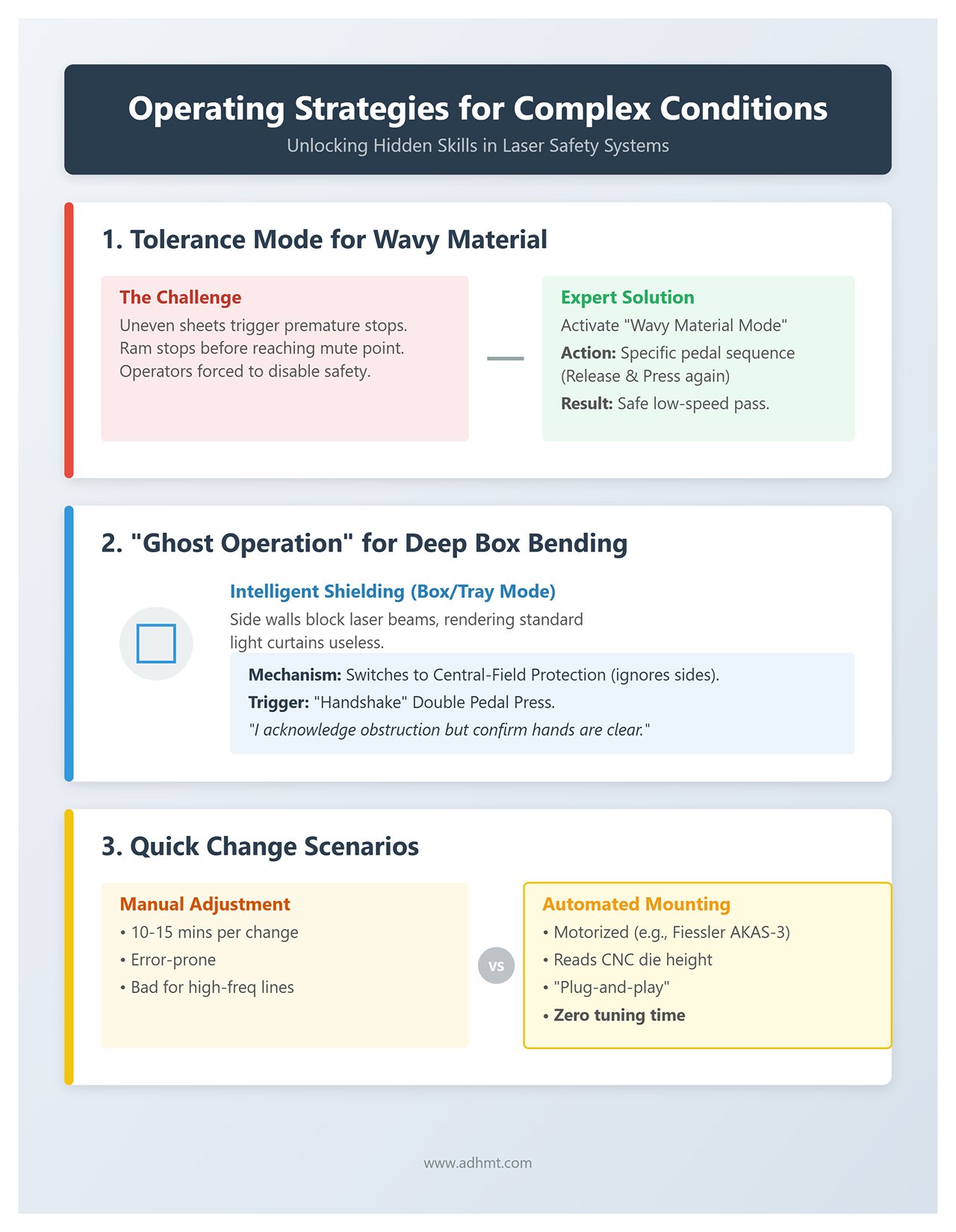
If you only operate the laser safety system in its “standard mode,” you’re wasting half of its potential. To handle non-standard conditions, you must unlock its hidden capabilities.
- Tolerance Mode for Wavy Material
- Challenge: Uneven or warped sheets can trigger premature laser interruptions, causing the ram to stop before reaching the mute point—forcing operators to disable the safety system.
- Expert Solution: Activate the system’s Wavy Material Mode. In this mode, when the laser detects surface irregularities, it won’t shut the machine down immediately. Instead, the operator can use a specific pedal sequence—typically releasing and pressing again—to safely pass through the obstructed zone at controlled low speed, maintaining both workflow continuity and safety.
- “Ghost Operation” for Deep Box Bending
- Challenge: In the final bending stages of deep boxes, the side walls inevitably block the laser beams on both sides—rendering traditional light curtains useless in such scenarios.
- Intelligent Shielding: Activate the Box/Tray Mode. The laser protection field then intelligently switches from full-field to central-field protection—ignoring the front and rear side beams while maintaining safety directly beneath the punch tip.
- Activation Trigger: This typically requires a “handshake” between operator and machine—such as performing a double pedal press. Upon receiving the signal, the system interprets it as “I acknowledge the side obstruction but confirm hands are clear,” allowing the ram to continue its descent.
- Quick Change Scenarios
- Automated Mounting Systems: For high-frequency production lines changing dies more than five times a day, manually adjusting the laser emitter height is both time-consuming (10–15 minutes per change) and error-prone. It’s strongly recommended to use a motorized automatic lift mount (e.g., Fiessler AKAS-3 motorized). This system reads CNC die height parameters directly and positions the laser via servo control, achieving true “plug-and-play” setup and reducing safety tuning time to zero.
IV. Operation and Maintenance: Building a Human–Machine Safety Culture
Hardware installation marks only the beginning of the safety journey. The real challenge lies in integrating this high-precision system into the daily rhythm of the workshop. If the laser safety system is the “nervous system” of the press brake, then systematic operation and maintenance are its “lifeblood.”
Building a human–machine collaborative safety culture transforms passive compliance into proactive performance improvement.
4.1 Operator Empowerment and Training: From Knowing How to Knowing Why

In the era of traditional light curtains, operator training was often rudimentary: “Don’t put your hand in, and press the pedal all the way down.” Under a laser protection system, however, that crude logic isn’t just unsafe—it’s a direct hit to efficiency. The new generation of training must focus on building fresh muscle memory and cognitive discipline.
- Counter-Intuitive Drills
- Rebuilding Foot Pedal Muscle Memory: Operators must unlearn the old habit of “pressing the pedal to the floor.” On machines equipped with advanced systems like Lazer Safe or Fiessler, the foot pedal is more than a power switch—it’s a kind of Morse code for communicating with the safety controller. Especially when bending sidewalls (Box Mode) or corrugated panels, operators must master the rhythm of “tap—pause—confirm—press again.” This sequence acts as a handshake protocol, signaling to the controller: “I’m aware the sidewall blocks the beam, but I confirm it’s safe—proceed at low speed.”
- Sense of Critical Speed Control: The challenge in training lies in helping operators perceive the “speed change point.” If the pedal is pressed too forcefully, the hydraulic system may overshoot, triggering a laser safety alarm due to insufficient braking distance. Only by smoothly “gliding” through the change point can one maintain an optimal production rhythm.
- Visual Status Management: Reading the Machine’s Micro-Expressions
- Decoding LED Signals: Operators shouldn’t rely solely on CNC error codes—that’s too slow. They should learn to read the LED indicators directly on the receiver (RX). For example, in the Sentinel system, a steady orange light generally means “system operational but optical signal weakened (needs cleaning),” whereas a flashing red light or steady red light indicate “beam obstruction” and “system fault,” respectively. Understanding these signals instantly can save about 30 seconds on each troubleshooting session.
- Self-Checking for ‘Phantom Stops’: When the machine suddenly halts without clear reason, operators should perform a quick environmental check—look at nearby windows or skylights. Intense sunlight or flickering fluorescent lamps are often the culprits behind false sensor alarms.
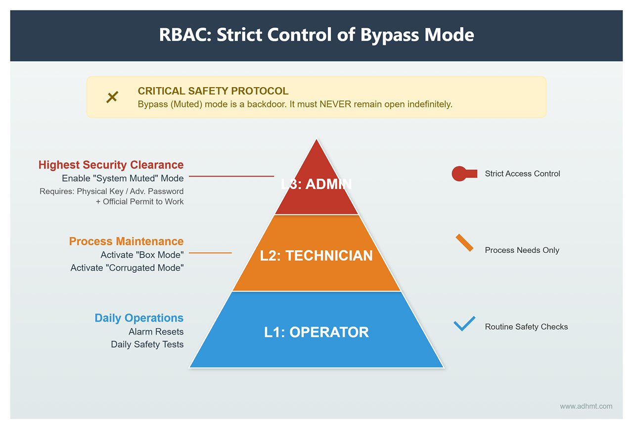
- Role-Based Access Control (RBAC)
- Strict Control of Bypass Mode: The bypass (muted) mode is effectively a backdoor to the safety system and must never remain open. The HMI should enforce digital access boundaries with tiered permissions:
- L1 Operator: Authorized only for alarm resets and daily safety tests.
- L2 Technician: Permitted to activate “Box Mode” or “Corrugated Mode” as required by process needs.
- L3 Administrator: Only personnel with a physical key or advanced password can enable “System Muted” mode, and this must be accompanied by an official Permit to Work document.
- Strict Control of Bypass Mode: The bypass (muted) mode is effectively a backdoor to the safety system and must never remain open. The HMI should enforce digital access boundaries with tiered permissions:
4.2 Preventive Maintenance and Periodic Calibration: Rejecting ‘Pseudo-Safety’
The performance of a laser safety system depends not only on its electronic components but also on the cleanliness of its optical path and the responsiveness of its hydraulic system. Neglect in any area can turn a costly PL e-level safeguard into a mere decoration.
- Daily Test Ritual
- Standardizing the Test Rod: Abandon the makeshift practice of using random wooden sticks. The workshop must be equipped with certified test rods conforming to EN 12622: 14mm (finger simulation) or 20mm (knuckle simulation).
- Mandatory Startup Procedure: Integrate the safety test logic into the PLC startup sequence. At the start of each day or shift, operators must interrupt the laser beam with the test rod during the slide’s fast descent. If the slide fails to stop decisively before contact, the system locks itself out of production mode. This digital traceability ensures accountability for safety compliance.
- Optical Component Maintenance: Precision Begins with Cleanliness
- Solvent Red Line: Never use acetone or strong industrial degreasers to clean laser lenses (typically made of PMMA). These solvents can cause instant fogging and permanent damage.
- Recommended Solution and Technique: Use >90% pure isopropyl alcohol (IPA). Avoid dry wiping—dust particles often contain quartz, which is harder than glass and can scratch lenses. The correct method is to first blow away loose dust with an air blower, then gently wipe in one direction with an IPA-dampened lint-free cloth.
- Annual Compliance Certification: Stop Time Measurement
- Why It Matters: Over years of use, valve wear and spring fatigue can extend the physical braking time from the original 80ms to 120ms. For a close-protection laser system, that 40ms delay could turn a safe zone into an amputation hazard.
- Execution Standard: Follow ISO 13855 guidelines and conduct professional testing at least every 12 months (every 6 months for high-frequency machines). Use certified stop-time testers (e.g., from Smartscan or Pilz), and recalculate safety distances based on the worst-case measured stop time.
4.3 Data-Driven Safety Management: From Reactive Fixes to Predictive Insight
Modern laser safety controllers are no longer isolated systems—they are data-generating hubs. By mining this data, safety managers can shift from reacting to incidents to preventing them altogether.
- Using Logs to Capture Near-Miss Events
- Unearthing the Data Goldmine: High-end controllers like Sentinel Plus record thousands of recent event logs. Safety managers should export these monthly and analyze the frequency and timing of “Error: Obstruction detected.”
- Scenario Reconstruction and Optimization: If a machine repeatedly triggers obstruction alarms between 2 p.m. and 4 p.m., the cause may not be operator error but glare from reflective workpieces or operator fatigue. This kind of near-miss data highlights hidden risks—perhaps calling for adjustments in lighting or shift schedules.
- Digital Fingerprints of Unsafe Behavior
- Monitoring Bypass Duration: Track the cumulative monthly runtime of “muted” mode. If a machine spends more than 5% of its time bypassed, it’s a red flag—either poor mold design is forcing workers to disable safety systems, or shop-floor discipline has collapsed. Immediate corrective action is required.
- Maintenance Alerts: Optical Power Decay Curve
- Predictive Maintenance: Many advanced receivers now feature a “Signal Margin” monitoring function. Don’t wait for the red warning light before taking action. When backend data shows signal strength gradually dropping from 100% to around 70%, it’s time to schedule lens cleaning or optical alignment. This form of Condition-Based Maintenance (CBM) helps prevent sudden machine downtime right when production deadlines are most critical.
V. Emerging Trends: The Fusion of AI and Intelligent Manufacturing
As the wave of Industry 4.0 sweeps through the metal fabrication sector, press brake laser safety systems are undergoing a profound transformation—from passive defense to proactive intelligence.
In cutting-edge production facilities, safety devices are no longer just emergency stop switches; they are evolving into the machine’s “sensory organs” and the data network’s “nerve endings.” The future is already here: laser protection is redefining the boundary between safety and efficiency.
5.1 Integration of Laser Safety and Quality Control (Security + Quality)
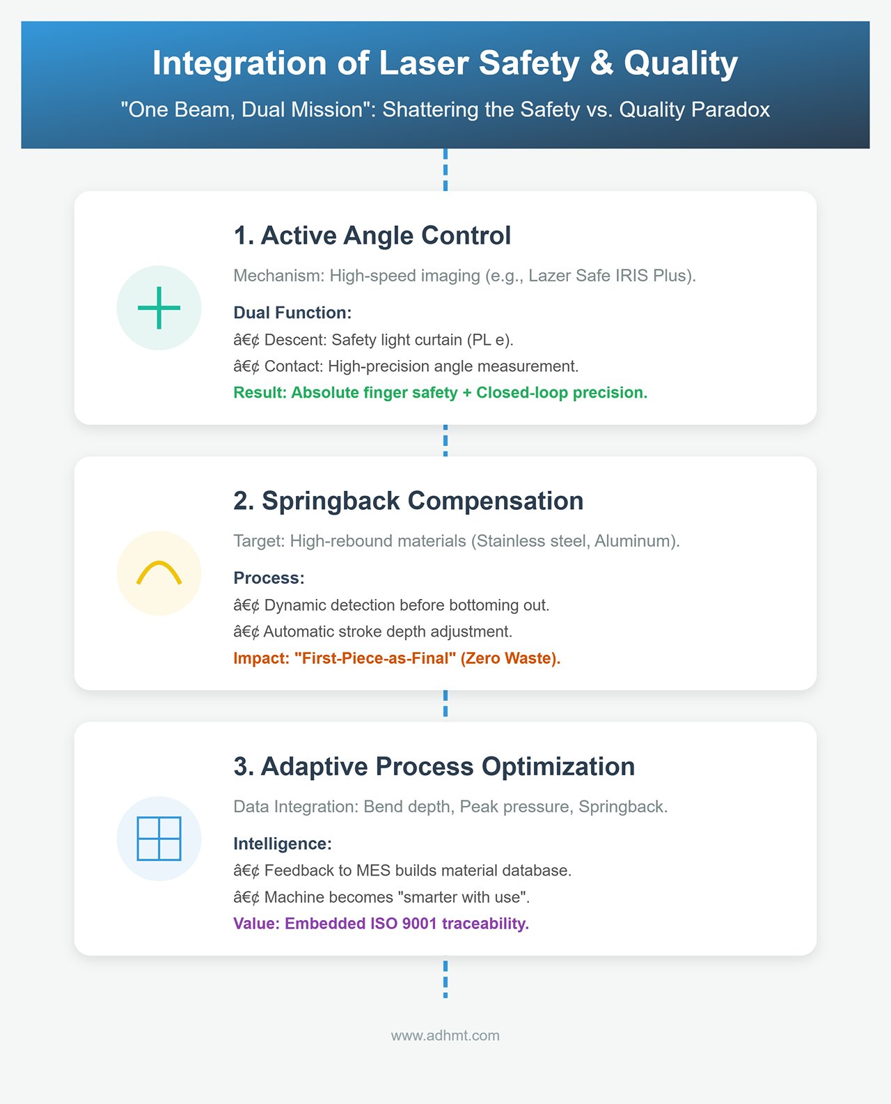
For decades, manufacturing has suffered from a stereotype: safety and quality are enemies, since safety supposedly means slowing down. However, the new generation of laser protection systems has shattered this paradox through the concept of “one beam, dual mission.” Today’s sensors protect both people and product quality.
- Active Angle Control: Modern high-end laser systems (such as Lazer Safe IRIS Plus or Data M solutions) integrate high-speed imaging technology. During the press descent, they act as safety light curtains at Performance Level e; at the instant the die contacts the sheet, they switch to high-precision angle measurement instruments. The system scans the bending angle of the sheet in the V-die in real time, sending closed-loop feedback to the CNC controller to fine-tune ram depth. The result: absolute finger safety and simultaneous “measure-as-you-bend” precision.
- Springback Compensation and “First-Piece-as-Final” Production: For materials prone to high springback—like stainless steel or aerospace aluminum alloys—traditional methods often require multiple test bends. A laser safety system with integrated angle measurement can, within milliseconds before bottoming out, dynamically detect material rebound and automatically adjust stroke depth. Practical impact: this eliminates trial-and-error waste. For high-value, low-volume parts, it delivers true “first-piece-as-final” manufacturing—protecting both the operator’s hands and the company’s profit margins.
- Adaptive Process Optimization: Real-time data on bend depth, peak pressure, and springback collected by the laser system no longer sits idle in logs—it’s fed back to the MES to build a material database. The machine literally becomes “smarter with use,” automatically optimizing dwell time and pressure based on batch-to-batch hardness variations. This is a benchmark case of embedding ISO 9001 traceability directly into safety hardware.
5.2 Next-Generation Intelligent Protection: From “Photoelectric” to “Cognitive”
If current AOPD systems are rule-based, the next generation will be cognitive. With AI algorithms entering the scene, machines are beginning to demonstrate human-like judgment.
- AI Behavior Prediction (Vision-Based Prediction): Traditional laser protection follows a binary logic—“interruption equals stop.” In contrast, AI-powered vision systems, leveraging edge computing platforms like NVIDIA Edge AI, can recognize operator skeletal posture and motion intent in real time. Intent recognition: AI can tell the difference between a hand guiding material and one accidentally entering the danger zone. If hand speed and trajectory suggest normal handling within a safe area, the system won’t trigger an abrupt stop—instead, it dynamically adjusts the muted zone. This “flexible safety boundary” allows machines to work in harmony with human rhythm rather than forcing humans to conform to mechanical rigidity.
- Volumetric Guarding and Human–Robot Collaboration: As collaborative robots (Cobots) become common in bending cells, two-dimensional linear lasers are no longer enough. Advanced 3D time-of-flight (ToF) scanners—such as next-generation versions of the Pilz SafetyEYE—create multiple dynamic virtual safety shells in 3D space. Practical scenario: when the robot arm enters the loading area, the system lights green; if a human operator steps into the robot’s swing radius, the system commands a speed reduction instead of a full stop. This achieves true fluid cooperation among humans, machines, and materials within the same workspace—no fences, no isolation.
- Cloud-Based Safety Monitoring and OTA Updates: OEMs now monitor the safety status of tens of thousands of machines worldwide in real time via the cloud. This “God’s-eye view” is revolutionizing maintenance and support models:
- Predictive Maintenance: If data shows a machine’s hydraulic valve braking time slightly increasing, the cloud service center can alert the customer to replace components up to two weeks before a “stopping distance fault” occurs—cutting unplanned downtime to zero.
- Algorithm OTA: When new high-reflectivity composites or coated materials appear, manufacturers can push optimized optical filtering algorithms via over-the-air (OTA) updates—enabling improved interference resistance without any hardware replacement.
5.3 Industry Best Practice Case Library
Theory must ultimately prove itself in practice. The following three real-world cases demonstrate how advanced laser safety systems translate into measurable business value.
| Industry Case | Challenge / Background | Solution | Results & Business Value |
|---|---|---|---|
| Automotive Parts Manufacturing (The Secret Behind a 15% OEE Boost) | A Tier-1 supplier faced intense delivery pressure. Existing light curtains forced a slow 20mm approach distance on every bend cycle, hampering speed. | Upgraded to a matrix-style laser system featuring “automatic speed point optimization.” | • Slow approach distance reduced from 20mm to 4mm. • 15% increase in OEE due to saved "air travel" time. • ROI achieved in just 5 months. |
| Precision Sheet Metal Fabrication (Solving the “Too Small to Hold” Dilemma) | Processing narrow 50mm server brackets required hands close to the die. Traditional light curtains caused instant halts, leading to widespread disabling of safety devices. | Introduced an intelligent laser system supporting “Box Mode” and “profile masking,” used alongside magnetic hand tools. | • Automatically masked a central 100mm zone while protecting sides. • Compliance jumped from 0% to 100%. • Eliminated fear of injury and improved workflow smoothness. |
| Heavy Machinery Manufacturing (Dual-Machine Synchronization at High Tonnage) | Bending 12m long steel with a 1,000-ton setup caused frame deflection. Fixed laser emitters frequently misaligned due to impact forces, triggering false shutdowns. | Implemented a laser system mounted on a motorized self-alignment base for continuous precision. | • System automatically fine-tunes emission angle (like a tank stabilizer). • Resolved “false faults” caused by vibration or deformation. • Ensured uninterrupted production of large components. |
VI. Summary and Action Roadmap
Amid the digital transformation of sheet metal processing, the Laser Safety System (LSS) for press brakes is no longer a mere compliance accessory—it has evolved into a next-generation productivity enabler connecting people, machines, and data. It marks the industry’s transition from the era of trading efficiency for safety to an age where safety itself drives efficiency through intelligent synergy.
6.1 Core Value Review: Safety Is an Asset, Not a Cost
A closer look at the evolution of press brake safety reveals a clear path from physical barriers to digital empowerment. The true value of laser protection lies in its transformative dual advantage:
- For operators, it provides invisible protection. With millisecond-level response and adaptive guarding logic, it eliminates the blind spots and psychological strain caused by conventional light curtains. Even new operators can work confidently at close range, effectively removing the inefficiency born of fear.
- For enterprises, it functions as a hidden profit center. By minimizing non-productive slow-feed time and ensuring “first-piece-as-final” quality control, LSS dramatically improves OEE (Overall Equipment Effectiveness). More importantly, it builds a solid legal firewall—shielding the company from crippling injury claims and downtime crises.
Laser protection is not only a key enabler of automated bending but also the perfect intersection of corporate social responsibility and lean manufacturing principles.
6.2 Enterprise Action Guide (30-60-90 Day Plan)
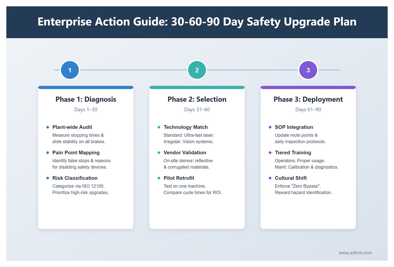
Upgrading a safety system is not a one-step process. Hasty procurement often leads to implementation failures. The following phased blueprint is designed to help manufacturers execute a smooth and efficient technological transition.
Phase 1: Diagnosis and Assessment (Days 1–30)
- Plant-wide Audit: Conduct a “health check” on all press brakes. Focus on measuring the stopping time of older hydraulic systems and document each machine’s slide stability data.
- Pain Point Mapping: Gather operator feedback. Which parts frequently cause false stops? Which processes force workers to disable safety devices? Match these pain points against current equipment limitations.
- Risk Classification: According to ISO 12100, categorize machines as “high-risk—urgent upgrade,” “moderate risk—deferred upgrade,” or “obsolete—recommended for replacement.” Prioritize budget for high-risk, high-utilization machines.
Phase 2: Selection and Pilot Implementation (Days 31–60)
- Precise Selection: Choose technology based on identified pain points. For standardized enclosures, opt for ultra-fast matrix laser systems; for diverse or irregular parts, consider vision-based imaging systems with advanced image processing capabilities.
- Vendor Evaluation: Don’t rely on presentations alone. Require suppliers to conduct on-site demos with sample units. Pay special attention to performance with reflective materials, corrugated sheets, and sidewall bending scenarios.
- Pilot Retrofit: Select one main production machine for trial integration. Record pre- and post-upgrade cycle times and tool change durations to validate the ROI with real production data.
Phase 3: Full Deployment and Institutionalization (Days 61–90)
- SOP Integration: Incorporate laser system procedures into Standard Operating Protocols (SOPs). Define “mute point” configurations, special mode activation workflows, and daily inspection standards.
- Workforce Empowerment: Conduct tiered training sessions. Operators must learn proper usage, while maintenance staff should master optical calibration and error code diagnostics.
- Cultural Transformation: Establish a “zero bypass” incentive system. Reward employees who identify safety hazards or propose process improvements, and enforce strict penalties for disabling safety features. Make safety awareness an integral part of corporate culture.
6.3 Essential Insights for Decision-Makers: Common Pitfalls to Avoid
In the face of six-figure investment decisions, leadership must stay vigilant against the following misconceptions and implementation traps:
Beware of Low-Cost “Fake Laser” Solutions
- Misconception: Assuming all light-emitting sensors are the same and choosing cheaper models with only basic photoelectric switch functions.
- Reality: A genuine LSS must meet stringent IEC 61496 and ISO 13849 certifications (Type 4 / PL e). Low-end single-beam sensors lack both adaptive protection and self-diagnostic capability. In the event of an accident, such “decorative safety” becomes a liability in legal proceedings.
Don’t Overlook the Machine’s Core Condition
- Misconception: Believing that installing a top-tier laser system can revive an aging machine.
- Reality: A laser system is a precision multiplier, not a miracle cure. If the press brake’s slide guides are worn, hydraulic valves sluggish, or frame rigidity compromised, even the best laser system will struggle—leading to endless false alarms. In such cases, mechanical overhaul or machine replacement must come first.
Prioritize Software and Local Support
- Misconception: Focusing solely on hardware specs while ignoring software flexibility and service responsiveness.
- Reality: As bending technologies evolve, the ability to adapt via software updates—to new materials like high-strength steel or new forming techniques—determines long-term value. Because any LSS fault halts production, supplier commitments to 24-hour on-site or remote support are critical to delivery reliability. Service capability should weigh as heavily as hardware performance in vendor selection.
Safety is non-negotiable, and efficiency has no finish line. May this guide serve as your foundation for building a zero-accident, high-productivity, and future-ready bending workshop.


