I. Introduction
The laser cutting machine has revolutionized the manufacturing industry by providing precise and efficient methods for cutting various materials. Central to this groundbreaking technology is the software that drives its operations.
Laser cutting software refers to the computer programs and systems that control the laser cutting machines. Software in laser cutting machines plays a critical role in determining the precision, efficiency, and overall performance of the cutting process.
Advanced laser cutting software integrates features like automatic nesting, real-time monitoring, and precise control over laser power and speed. Ensuring software compatibility with the specific type of laser-cutting machine is crucial.
If you are currently evaluating hardware options, you can explore both the Single Table Fiber Laser Cutting Machine and the Double Table Fiber Laser Cutting Machine to better understand which configuration aligns with your production scale.
Compatible software will support the necessary file formats, provide the required vector or raster data, and integrate seamlessly with the machine's firmware. This compatibility ensures smooth operation, reduces the risk of errors, and enhances the machine's overall performance.
This guide explores various laser-cutting machine software, highlighting key features to help users make informed decisions. It reviews top software solutions, offering insights into their benefits and drawbacks.
The guide also provides advice on choosing the right software for different needs, alongside installation tips and troubleshooting. By the end, readers will understand how to use laser cutting software to enhance manufacturing processes, improve precision, and boost efficiency. For a deeper understanding of machine performance, you can also download detailed brochures from the official site.

Advanced laser cutting software integrates features like automatic nesting, real-time monitoring, and precise control over laser power and speed. Ensuring software compatibility with the specific type of laser-cutting machine is crucial.
Compatible software will support the necessary file formats, provide the required vector or raster data, and integrate seamlessly with the machine's firmware. This compatibility ensures smooth operation, reduces the risk of errors, and enhances the machine's overall performance.
This guide explores various laser-cutting machine software, highlighting key features to help users make informed decisions. It reviews top software solutions, offering insights into their benefits and drawbacks.
For readers looking to extend the capabilities of their machines, consider exploring Laser Cutting Machine Accessories and Upgrades that can complement your chosen software for optimal results.
II. Types of Laser Cutting Machine Software
2.1 Design and Import Capabilities
This is the first—and arguably the most crucial—point of contact between the software and human creativity. Think of it as a customs officer, deciding which “cargo” (design files) can enter smoothly and which get held up. A robust interface can save you hours each day by eliminating needless back-and-forths and time-consuming file fixes.
(1) Broad-Spectrum File Compatibility
Your designer works in Adobe Illustrator, the engineer in SolidWorks, and your client sends over a PDF? No problem. Professional-grade software should be a true “linguistic virtuoso,” capable of seamlessly reading all industry-standard formats. Vector formats (DXF, DWG, AI, SVG) are the blueprint of cutting—they define every precise path the laser must follow.
Strong compatibility means you can open engineering files directly, without the headache of converting formats across multiple programs. Raster/bitmap formats (JPG, PNG, BMP) are the language of engraving. The software must intelligently convert these pixel-based images into a matrix of varying laser burn depths, suitable for precise engraving.
(2) Built-in Graphic “First Aid” Tools
Imported drawings are rarely flawless. A novice designer may leave open paths or accidentally draw overlapping lines. Without built-in repair tools, you’d have to send the file back to the design team—losing hours in the process. Top-tier software comes equipped with “first aid” features that let you fix these problems instantly on-site. If your current system lacks such capabilities, it’s worth consulting experts through the contact us page to learn which software or machine combinations can enhance this workflow.
Node editing works like shaping a length of soft wire by hand—you can drag, add, or delete nodes along a path directly in the software, fine-tuning the design down to the last millimeter. Automatic path closure addresses one of the most common and dangerous errors: an open contour will cause the laser to leave a gap after completing the loop. This feature automatically detects and “welds” those gaps with a single click.

If two lines are perfectly overlapping, the laser will waste time cutting the same line twice—potentially burning the material's edge. This function acts like a meticulous quality inspector, instantly identifying and deleting duplicate lines.
2.2 CAM Intelligent Core
If design importing is about “reading the blueprint,” then the CAM (Computer-Aided Manufacturing) core is about “developing the optimal battle plan.” This is the software’s strategic brain, and the sophistication of its algorithms directly impacts your production costs and final product quality.
(1) Path Planning Algorithms
A basic program will simply trace the lines, but an intelligent CAM core operates like a grandmaster of Go—thinking globally to find the most efficient sequence:
1)Inner Contour First: It always cuts the inner holes of a part before the outer contour. Why? Imagine cutting out a cookie’s shape first—once the cookie moves, how could you precisely poke a hole in the middle? This simple logic prevents countless defective pieces caused by part displacement.
2)Shortest Idle Moves: Any movement of the laser head between different parts is pure waste. Advanced algorithms work like a high-powered GPS, calculating the shortest possible non-cutting path between all parts to minimize idle time.
3)Heat Management & Obstacle Avoidance: When cutting densely packed thin-sheet parts, the algorithm will deliberately “skip around” to distribute heat evenly, preventing local warping. It also intelligently reroutes around already-cut pieces that might have lifted from the sheet, protecting the laser head from collisions—critical for avoiding catastrophic machine failures.
If you are using high-end fiber systems such as the Double Table Fiber Laser Cutting Machine, these algorithms can significantly amplify your throughput efficiency.
(2) Intelligent Nesting
This is the ultimate weapon for turning material savings directly into profit. The core principle: fit as many parts as possible onto a single sheet, like a game of Tetris.
1)True-Shape Nesting: It recognizes the actual irregular shapes of parts and interlocks them like puzzle pieces. Compared to basic rectangular nesting, this can boost material utilization by 15% or more. For expensive metal sheets, that translates into significant savings month after month.
2)Common-Line Cutting: When two rectangular parts are placed side-by-side, the software can arrange for a single cut to serve as the edge for both, saving both time and energy with every shared cut—small efficiencies that add up to big gains.
(3) Lead-Ins and Micro-Joints
1)Lead-Ins: Piercing the material leaves a minute blemish. To avoid placing this flaw on a valuable part edge, the software smartly starts from a lead-in path outside the part and finishes from within, ensuring spotless, smooth cut edges.
2)Micro-Joints: When cutting small parts, once freed, they may fall or be blown away by airflow. Micro-jointing deliberately leaves a few hair-thin connectors—like the perforations on a postage stamp—to keep parts temporarily fixed to the sheet. After cutting, the operator can simply snap them free by hand—safe and efficient.
For guidance on advanced CAM workflows, consider watching How to Use the S875 System for Of line Programming and Importing Drawings to see practical demonstrations.
2.3 Parameter and Material Library
This is the software’s “memory core,” capturing the “secret recipes” of skilled operators into standardized, easily retrievable data—a foundation for moving beyond reliance on veteran know-how to achieve scalable, stable production.
(1) Building a Dedicated Process Database
The software lets you create a dedicated “process card” for each material type and thickness. Each card holds the optimal parameter set—determined through rigorous testing—including laser power, cutting speed, gas pressure, focal position, and more.
(2) One-Click Retrieval & Absolute Consistency
Once built, the database becomes a powerhouse. Any operator, regardless of experience, simply selects “3mm Stainless Steel” or “5mm Acrylic” from the menu, and the software auto-loads all the optimal pre-set parameters. This means that whether it’s today or next month, whether John or Sarah is running the machine, the output quality for a particular batch remains perfectly consistent—this is the essence of industrialization.
2.4 Simulation and Real-Time Monitoring
This is the software’s “foresight” and “sensory” system—helping you avoid costly mistakes in the virtual world and make fine real-time adjustments in the physical one. It's the final step toward truly intelligent production.
(1) Visual Simulation
Before you hit the “Start” button, the software simulates the entire cutting process on-screen. You can clearly see the exact movement of the laser head and check if the cutting order makes sense. More importantly, it provides highly accurate estimates of total processing time—critical for production scheduling and quoting—turning your promises into data-backed commitments rather than guesses.
(2) Real-Time Monitoring and Dynamic Adjustment
This is no longer science fiction. Modern high-end software gives machines a near-biological sense of perception and responsiveness.
1)Dynamic Power Adjustment: High-speed straight cuts require full power, but slowing at sharp corners without adjusting power causes heat buildup, leading to burnt, darkened edges. This function automatically “throttles up” or “down” based on the laser head’s real-time speed, ensuring flawless cuts at any point—corner or straight line.
2)Fly Cutting: When processing dense hole patterns in thin sheet (like a mesh), the traditional method stops and starts for each hole. Fly cutting keeps the laser head in continuous high-speed motion above the pattern while the laser pulses rapidly, “sweeping” across entire rows of holes. The result? Not just a percentage gain, but multiple times the efficiency.
In summary, these core features work together to form a complete, closed-loop system—from receiving instructions and intelligently planning, to executing with precision and self-optimizing performance. Understanding how they function and the value they bring is the very first, and most crucial, step toward unlocking your laser cutter’s full potential—helping you reduce costs while boosting efficiency.
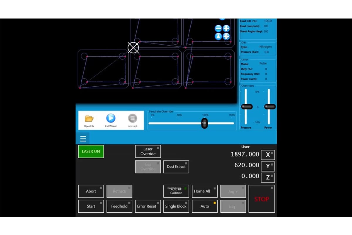
2.5 Control Software
Control software is typically embedded within the laser cutting system or provided by the machine’s manufacturer, and is responsible for carrying out the cutting process. It communicates directly with the hardware, orchestrating the laser, worktable, and other mechanical components.
This software manages real-time command processing, adjusts feed rates, and monitors system status to ensure both precision and safety. Notable examples include proprietary solutions tailored for specific machines, such as Epilog’s JobControl and Trotec’s JobControl Vision.
2.6 Simulation Software
Before actual production begins, simulation software plays a critical role in optimizing and verifying laser cutting processes. By generating a virtual representation of the cutting sequence, it allows users to identify and fix potential issues—such as collisions or inefficient toolpaths—without wasting materials.
Simulation software helps minimize trial-and-error during setup, thereby increasing productivity. Tools like TruTops and Lantek Expert Cut offer advanced simulation capabilities that enable accurate and efficient cutting results.
2.7 Nesting Software
Nesting software is designed to arrange parts to be cut in the most efficient layout on a given sheet of material, maximizing material usage and reducing waste. This is especially important in industries where material costs are significant.
Advanced nesting algorithms calculate the optimal placement of shapes within the available material space, reducing costs and improving production efficiency. Popular nesting solutions include SigmaNEST, NestMaster, and ProNest, all of which feature powerful material optimization tools.
2.8 Industry-Specific Software
Certain industries require dedicated laser cutting software that meets unique operational needs. For example, in fashion and textiles, solutions like Optitex provide specialized fabric pattern cutting capabilities.
Similarly, the metal fabrication sector can benefit from software such as Metalix or BySoft, which are designed to handle complex metalworking processes. Industry-specific tools typically include features tailored to address sector-specific challenges, delivering customized solutions that boost overall productivity.
2.9 Open-Source and Free Software
For beginners or those working with limited budgets, open-source and free laser cutting software can provide essential functionality without requiring major investment. Programs like Inkscape (with LaserCut plugins) and LaserWeb offer entry-level solutions suitable for hobbyists and small businesses.
III. Top Laser Cutting Software Solutions
3.1 LightBurn
- Overview: LightBurn is a popular laser cutting software for CO2 and diode laser systems. It offers powerful design, editing, and control tools for laser cutting and engraving.
- Key Features:
- Cross-platform (Windows, macOS, Linux).
- Easy vector editing tools, image tracing, and arranging designs.
- Direct control over laser settings such as speed, power, and acceleration.
- Supports a wide range of file formats (AI, SVG, DXF, PDF, etc.).
- Best For: Hobbyists and professionals who need an all-in-one software with a user-friendly interface.
3.2 RDWorks
- Overview: RDWorks, developed by Ruida, is a free laser cutting software designed to work with Ruida controllers. It is commonly used in industrial laser cutting applications.
- Key Features:
- Compatible with various file formats, including DXF and AI.
- Supports complex layer-based cutting operations.
- Allows detailed control over cutting parameters like speed and power.
- Basic design and editing tools for preparing files.
- Best For: Industrial applications where Ruida controllers are used.
3.3 Adobe Illustrator (with Plugins)
- Overview: Adobe Illustrator is one of the most widely used design software for vector graphics. While it is not specifically made for laser cutting, its design capabilities are enhanced through plugins for laser cutting integration.
- Key Features:
- Advanced vector design and editing tools.
- Third-party plugins like "LaserCut" or compatibility with laser cutting machines (e.g., Glowforge).
- Wide file format support (AI, SVG, PDF, etc.).
- Best For: Professionals who need powerful design features along with the ability to output laser-ready files.
3.4 CorelDRAW (with Plugins)
- Overview: CorelDRAW is another popular vector graphic software with extensive design features. It can be paired with laser cutting machines or plugins for laser control.
- Key Features:
- Precise vector design and editing.
- Compatible with various laser cutting machines through third-party plugins or built-in support.
- Supports multiple file formats, including DXF, SVG, and EPS.
- Best For: Designers who prefer a graphic-heavy software that also integrates with laser cutting tools.
3.5 Inkscape (with Laser Extensions)
- Overview: Inkscape is a free, open-source vector graphics software. With laser cutting extensions, it can be adapted for laser cutting and engraving tasks.
- Key Features:
- Open-source and free.
- Compatible with laser cutters via plugins or extensions like "Laser Tool."
- Supports standard file formats (SVG, DXF, EPS, etc.).
- Best For: Beginners and users looking for free software with decent design and cutting capabilities.
3.6 Autodesk AutoCAD

- Overview: AutoCAD is a professional-grade CAD software used for designing precise technical drawings. It is commonly used in industrial laser cutting for creating highly detailed vector paths.
- Key Features:
- Industry-standard for technical and mechanical design.
- Precise 2D vector design capabilities.
- Compatible with DXF and other formats used in laser cutting.
- Integrates with CNC and laser cutting machines.
- Best For: Engineers and professionals needing precise control over designs for complex laser cutting projects.
3.7 LaserWeb (Web-based)
- Overview: LaserWeb is an open-source, browser-based software for controlling laser cutters. It’s designed for people with some technical background and offers powerful control over laser operations.
- Key Features:
- Open-source and community-driven.
- Powerful control over laser cutting parameters.
- 3D and 2D design support.
- Multi-platform and browser-based (no installation required).
- Best For: Users looking for a web-based, open-source solution for laser cutting.
3.8 Fusion 360
- Overview: Autodesk’s Fusion 360 is a cloud-based 3D CAD, CAM, and CAE software platform. While it's primarily a 3D design software, it supports laser cutting with 2D vector designs and output files.
- Key Features:
- Supports both 2D and 3D design and manufacturing.
- Integrates with CNC machines and laser cutters.
- High-level customization of cutting parameters and settings.
- Cloud-based for collaboration and version control.
- Best For: Designers needing both 3D modeling and 2D cutting capabilities.
3.9 DraftSight
- Overview: DraftSight is a professional-grade 2D design and drafting solution. It is ideal for users who need precise 2D drawings for laser cutting.
- Key Features:
- Supports DWG and DXF file formats, ideal for laser cutting.
- Intuitive interface for technical and architectural drawings.
- Integration with CNC and laser machines.
- Best For: Engineers and architects looking for precise 2D design software with laser compatibility.
3.10 Glowforge App
- Overview: Glowforge offers its own cloud-based laser cutting software, specifically for Glowforge laser cutting machines. It is designed to be user-friendly for both beginners and professionals.
- Key Features:
- Browser-based software that doesn’t require installation.
- Intuitive, easy-to-use interface.
- Cloud-based storage and sharing.
- Works exclusively with Glowforge machines.
- Best For: Glowforge machine users, especially beginners and small businesses.
Ⅳ. Market Overview and Selection Strategy: Finding the Optimal Solution
Confronted with an overwhelming array of laser cutting software options, many decision-makers find themselves trapped in a state of “feature overload.” Choosing the right software isn’t merely about buying a tool—it’s about selecting an entire production philosophy. Instead of fixating on price comparisons, the wiser approach is to conduct a surgical-level analysis from three dimensions: ecosystem alignment, business lifecycle stage, and return on investment (ROI).
4.1 In-Depth Analysis and Positioning of Major Software Ecosystems
Today’s laser software market has clearly stratified into three distinct camps, each addressing specific production bottlenecks.
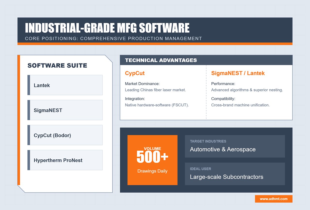
1. Industrial-Grade / Heavy Manufacturing Camp (The Industrial Giants)
Representative Software: Lantek, SigmaNEST, CypCut (Bodor), Hypertherm ProNest
- Core Positioning: More than just cutting—it’s about comprehensive production management.
- In-Depth Review:
- CypCut: Dominates China’s fiber laser cutting market with its tightly integrated hardware-software ecosystem. Its native optimization with FSCUT controllers enhances acceleration control and vibration suppression at the factory level. For most metal fabrication plants, it remains the go-to solution.
- SigmaNEST / Lantek: Both are software powerhouses with strengths in algorithms and data integration. They can unify workshop operations across different brands (e.g., TRUMPF, Bystronic, and local Chinese machines). Their standout feature—advanced nesting algorithms—enables “sheet-in-sheet” reuse of remnants and automatically computes optimal layouts overnight.
- Ideal Scenarios: Automotive, aerospace, and large-scale sheet metal subcontractors processing over 500 drawings daily.
2. Professional-Grade / SME Camp (The Professional Workhorses)
Representative Software: LightBurn, RDWorks
- Core Positioning: Exceptional cost-performance ratio and user experience.
- In-Depth Review:
- LightBurn: Often described as the “Swiss Army knife” of laser software, it delivers remarkable functionality for under $200. It revolutionized the non-metal and diode laser market with multi-layer parameter setups, camera-based alignment, and smooth vector editing. Its intuitive design has revitalized many otherwise clunky domestic controllers.
- RDWorks: As the native software for Ruida systems, it may look dated but offers rock-solid stability—making it the default choice for the majority of CO₂ laser cutters.
- Ideal Scenarios: Signage production, precision electronics prototyping, makerspaces, and customized gift workshops.
3. Entry-Level / Open-Source Camp (The Entry-Level Explorers)
Representative Software: LaserGRBL, Inkscape (with plugins)
- Core Positioning: Zero-barrier experimentation and learning.
- In-Depth Review:
- LaserGRBL: The best open-source G-code streaming software available. It’s straightforward and functional but lacks advanced path optimization and layer management. Think of it more as a “sender” than a full-fledged “editor.”
- Ideal Scenarios: Home DIY projects, STEM education, and simple one-off cutting tasks.
Expert Insight: Don’t attempt industrial production with entry-level software. While LaserGRBL is free, it lacks key features like “common-edge cutting” and “avoidance strategies,” leading to excessive idle travel and potential head collisions. In industrial settings, time is money—and safety is non-negotiable.
4.2 Decision Matrix: Software Selection by Business Lifecycle
A company’s software needs vary dramatically across its growth stages. The wrong match can be as inefficient as “a pony pulling a freight wagon” or as wasteful as “a cannon used to swat a fly.”
| Business Lifecycle | Core Challenges | Recommended Strategy | Key Evaluation Criteria |
|---|---|---|---|
| Start-up | Tight cash flow, limited staff skills | Prioritize flexibility. Choose LightBurn or the basic CypCut bundled with the machine. | Learning curve: Can a new operator master it within 3 days? Compatibility: Can it open customer-supplied AI/DXF files without conversion? |
| Growth | Rising order volume, cost sensitivity | Prioritize efficiency. Introduce CypNest or basic Lantek. | Nesting rate: Can it improve material utilization by 5–10% through algorithms? Path optimization: Does it support leapfrogging or fly-cutting for high-speed operations? |
| Mature | Data silos, multi-machine coordination issues | Prioritize integration. Deploy advanced SigmaNEST or Lantek modules integrated with ERP/MES systems. | API connectivity: Can it automatically sync inventory data? Quotation system: Can it generate precise quotes within seconds using historical data? |
4.3 Business Models and ROI Analysis
When purchasing software, many business owners focus only on the price tag, overlooking its potential as a value-adding asset. Let’s break down the real economics behind it.
Hidden Costs and Tangible Gains
- Evolving Licensing Models: The traditional hardware dongle model is giving way to subscription-based SaaS. Although subscriptions require annual fees, they ensure continuous access to the latest algorithms and updates.
- Case Example: A new release of a nesting software introduced an “obstacle avoidance path” algorithm that reduced the number of head lifts. This single update saved 20 seconds per sheet—translating into tens of thousands in extra annual output, easily surpassing the subscription cost.
ROI Model: How Software Helps You Make Money
Software ROI can be measured across three dimensions:
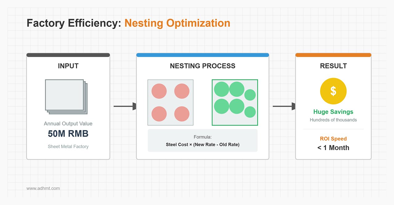
Material Yield
- Real-World Example: For a sheet metal factory with an annual output of 50 million RMB, a high-end nesting solution that increases utilization from 85% to 92% (a common gain) can save hundreds of thousands per year—often recovering software costs within the first month.
Consumable Life Extension
- Well-designed software employs smarter piercing strategies (e.g., multi-stage piercing) and cooling-point placement to reduce slag contamination on protective lenses. If it extends lens lifespan from daily to weekly replacements, the hidden profit is substantial.
Labor and Quotation Efficiency
- Software equipped with a one-click quoting feature can compress a task that would normally take an engineer 30 minutes—such as unfolding drawings and calculating material usage—into just one minute. This is more than a reduction in labor cost; it’s a fundamental leap in customer responsiveness. In a fiercely competitive market, the first to quote is often the one who wins the order.
Summary: Keep this golden rule in mind when choosing your system—hardware determines what you can do, while software determines how much you can earn. Never hesitate to invest in the “brain” of your operation; it’s the most cost-effective employee in your entire factory.
Ⅴ. In-Depth Analysis of Core Technologies: Mastering the Underlying Logic
If the fiber laser is the “heart” of the equipment, then the software’s core algorithms serve as its “nervous system.” Most operators only use about 20% of the software’s capabilities yet try to solve 100% of production challenges. This chapter dives into the foundational logic that truly defines processing quality and profit margins, helping you move from simply “operating software” to fully “mastering the process.”
5.1 Intelligent Nesting Algorithms: The Profit Excavator
In the metal processing industry—where raw material costs account for 60%–70% of total production costs—the efficiency of your nesting software directly determines your break-even point.
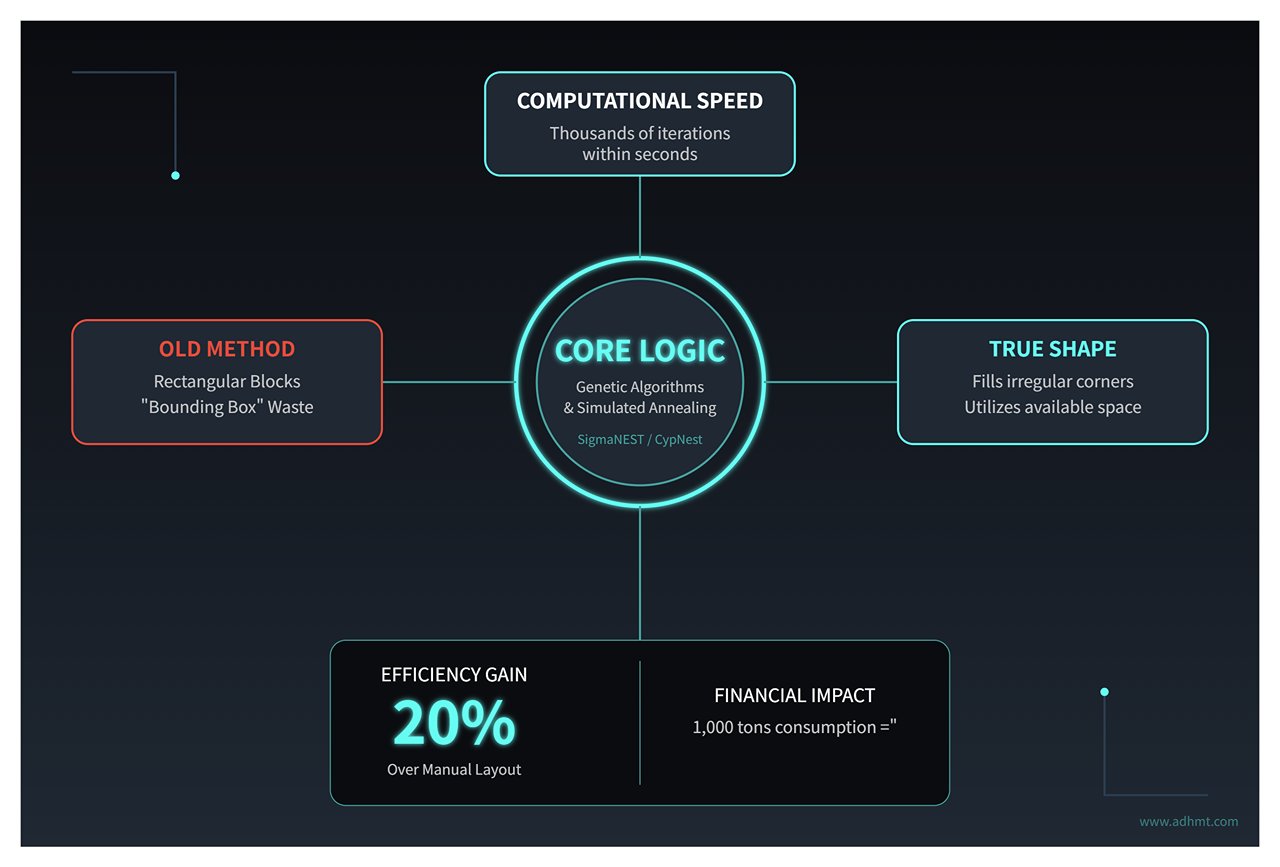
- Algorithmic Advantage: True Shape Nesting Traditional “bounding box” nesting treats each part as a rectangular block, leading to significant waste of scrap material. Modern industrial-grade software (such as SigmaNEST or CypNest) uses genetic algorithms and simulated annealing to achieve true shape nesting.
- Core Logic: Within seconds, the algorithm performs thousands of iterations, filling small parts into larger cutouts (treated as available space) or irregular corners to maximize material usage.
- Practical Value: For irregularly shaped parts, automatic nesting can improve material utilization by 15%–20% compared to manual layout. For a company consuming 1,000 tons of steel annually, that translates to tens of tons of recovered material—and pure profit.
- Common Line Cutting (CLC) This is not just about saving material—it also boosts efficiency. When the software detects two adjacent parts sharing a straight edge, it automatically merges their cutting paths so that only one cut is needed.
- Underlying Advantage: This reduces total cutting path length by 30%–40%, directly lowering oxygen/nitrogen consumption and nozzle wear, while also decreasing the number of piercings—one of the most time-consuming and lens-damaging steps in laser cutting.
- Pro Tip: Common-line cutting can lead to heat buildup. Advanced software mitigates this with strategies like “micro-joint + overcut” or “staggered common lines”, preventing thermal deformation and maintaining dimensional accuracy.
- Grain Direction Management This often-overlooked factor can be a silent killer. For brushed stainless steel or textured metals, incorrect grain orientation can result in product rejection or reduced strength (for instance, bent parts must be perpendicular to the rolling direction).
- Software Configuration: By locking the “grain constraint” parameter, the algorithm automatically avoids prohibited rotation angles during optimization, ensuring consistent grain direction across all parts.
5.2 Precision Cutting Control: The Battle of Microns
High precision is not solely defined by a machine’s repeatability—it depends equally on how the software manages the physical interaction between light and material.
- Kerf Compensation The laser beam has a measurable width (typically 0.1–0.3 mm). Without compensation, holes come out oversized, and circular parts undersized.
- Logic Setting: The software must automatically apply “offset” calculations during toolpath generation (using G41/G42 commands).
- Advanced Application: Kerf width varies by material thickness and nozzle type. Building a dynamic compensation library, rather than manually adjusting CAD dimensions, is crucial for standardized production.
- Lead-in / Lead-out Strategies The start and end points of a cut are the most likely spots to leave scars, burn marks, or bumps.
- Arc Lead-in: Ideal for thick carbon steel plates—its smooth entry prevents blowouts.
- Hook Lead-in: Useful in confined areas (like small holes) to protect the part’s contour from entry-point damage.
- No-Trace Micro-joint: By fine-tuning the overcut length, the end point separates cleanly without burrs—eliminating the need for post-processing or grinding.
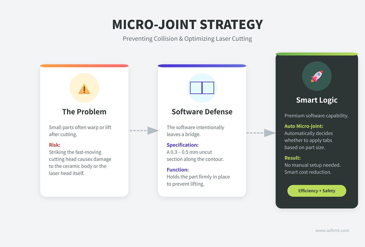
- Anti-Collision Logic for Micro-joints/Tabs Small parts tend to warp or lift after cutting, and if they strike the fast-moving cutting head, it can cause costly damage to the ceramic body or even the laser head itself.
- Software Defense: Leaves a 0.3–0.5 mm uncut section along the contour to hold the part in place.
- Smart Cost Reduction: Premium software supports “auto micro-joint,” automatically deciding whether to apply tabs based on part size—no manual setup needed.
- Corner Speed Control and Power Curve When the laser head slows to turn a sharp corner but the power stays constant, the localized heat density increases sharply, rounding or melting the edges.
- Solution: The software uses PWM (Pulse Width Modulation) to link laser power directly to cutting speed—when speed drops, power drops; when speed rises, power rises.
- Looping Logic: At sharp corners, the software automatically generates small circular loops, allowing smooth direction changes without sudden stops—eliminating corner burns entirely.
5.3 Building a Process Parameter Library: Your Company’s Digital Asset
Many factories still rely on veteran operators to fine-tune machines. When they leave, production quality fluctuates immediately. Converting experience into a parameter library within the software is the only way to eliminate dependence on individuals.
- The “Speed–Power–Frequency” Triad
- Speed: Controls efficiency—too fast, and the cut won’t penetrate; too slow, and the heat-affected zone (HAZ) widens, causing dross buildup.
- Power: Determines energy density and must be properly matched with speed.
- Frequency & Duty Cycle: Critical for fine cutting—high frequency yields smoother surfaces, while low frequency is better for thick-plate piercing.
- Refined Piercing Techniques The software should define differentiated piercing strategies for different material thicknesses:
- Pulse Piercing: Uses high-peak, low-duty-cycle laser pulses to gradually “drill” through the material layer by layer—much like digging a well—preventing blowouts when cutting thick plates.
- Ramp Piercing: The software dynamically lowers the laser focus during piercing while gradually increasing gas pressure. This “soft landing” technique can reduce piercing defects by more than 90%.
- Database Management Strategy: Don’t let key parameters live only in an operator’s notebook.
- Standardized Actions: Build an enterprise-level database indexed by material type, thickness, and assist gas (e.g., SS304_3mm_N2).
- Dynamic Updates: Whenever switching to a new batch of material or compensating for laser degradation, use the “Material Test Card” function to quickly detect optimal parameters and update them to the global database.
Expert Tip: Once you grasp these underlying principles, you’ll realize the software is far more than a drawing tool—it’s a sophisticated manufacturing process compiler. In the next section, we’ll move into hands-on practice to show how these principles translate into flawless finished parts.
Ⅵ. Ultimate Practical Guide: From Drawings to Finished Products
If the underlying algorithms are the “inner strength” of laser cutting, then the Standard Operating Procedures (SOP) are the “techniques” that determine success. Most machining accidents—whether collisions, scrap, or dimensional errors—stem not from equipment failure but from neglecting software details in the workflow. This chapter takes a practical approach to deconstruct the standardized process from design drawing to perfect final product.
6.1 Standardized Operating Procedure (SOP): The Moat of Zero Defects
This workflow is more than a list of steps—it’s the codification of experience into an unbreakable standard of execution.
Step 1: File Pre-Processing (The “Hygiene” Phase) Up to 80% of cutting issues arise from poor vector drawings. Directly importing a client’s DXF file into the software is the biggest rookie mistake.
- Vector Cleanup: In AutoCAD, develop the habit of using the
OVERKILLcommand to remove overlapping lines and zero-length segments in one click. UsePEDIT+JOINto repair broken paths (recommended tolerance: 0.01mm) and ensure all shapes are closed. - Node Optimization: For scan-generated vectors, use the “Optimize” tool in LightBurn to remove redundant nodes. Excessive nodes cause the laser head to accelerate and decelerate repeatedly, resulting in wavy cut edges.
- Unit Disaster Prevention: Always confirm whether the source file uses millimeters or inches. A single unit mistake can enlarge or shrink a part by 25.4 times, leading to severe material loss.
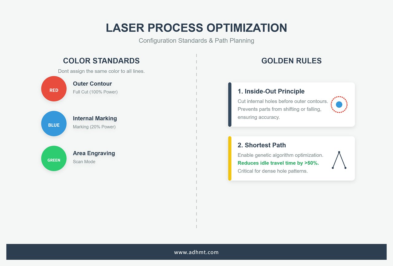
Step 2: Process Configuration and Layer Mapping Don’t assign the same color to all lines. Use the software’s layer system to establish a “visual fail-safe” mechanism:
- Color Defines Process: Set up company-wide standards—for example, red = outer contour full cut (100% power), blue = internal marking (20% power), green = area engraving (scan mode).
- Golden Rules of Path Planning:
- Inside-Out Principle: The software must cut internal holes before outer contours. Once the outer edge is cut, parts may fall or shift, making internal features impossible to machine.
- Shortest Path Optimization: Enable the genetic algorithm path optimization in CypCut or LightBurn. For parts with dense holes, this can reduce idle travel time by more than 50%.
Step 3: Simulation (The “Digital Twin”) Before pressing “Start,” always conduct a virtual run in the software.
- Collision Detection: In CypNest, the “Preview” feature highlights potential interference zones in red—especially useful for checking whether the lift height clears previously cut and warped parts.
- Time and Cost Estimation: Use advanced software like SigmaNEST with formulas such as
Total Time = Path Length / Cutting Speed + Piercing Count × 0.5s + Idle Travel.
This not only supports production planning but also enables precise quoting with ±5% accuracy.
Step 4: Human-Machine Interaction and Final Verification
- Physical Frame Check: Don’t rely solely on the screen. Run the machine along the bounding rectangle of the workpiece to confirm material size and ensure clamps are clear of the cutting path.
- Focus Calibration: For uneven sheets, activate CypCut’s capacitive height control system (BCS100). The Z-axis will automatically scan and map surface variations (±0.5mm precision), allowing the software to dynamically adjust the focus and maintain consistent kerf width throughout.
6.2 Advanced Vision and Positioning: Giving Machines “Eyes”
With the widespread adoption of CCD technology, software has evolved from blind command execution to possessing true visual perception.
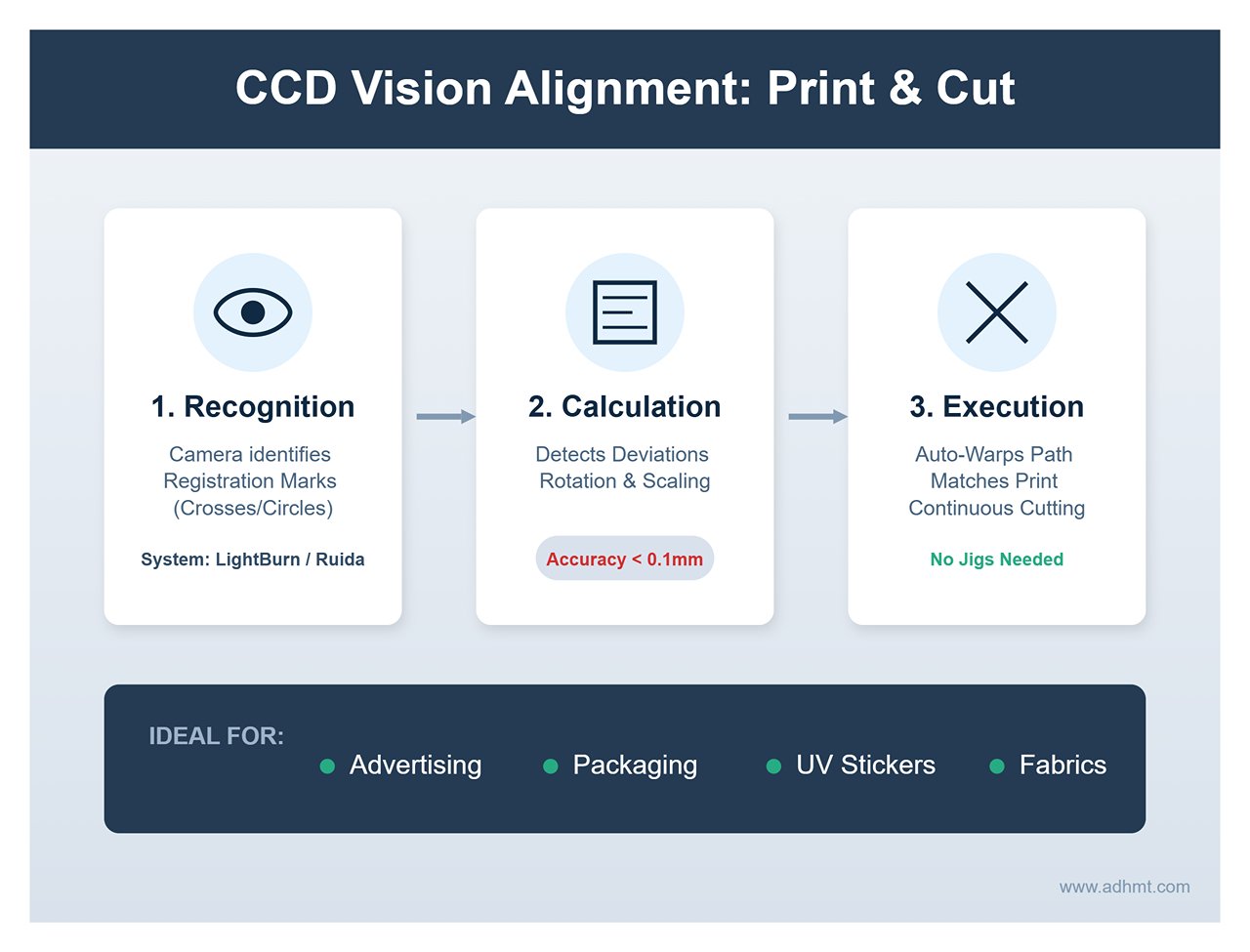
CCD Vision Alignment (Print & Cut) This is a game-changing feature in the advertising and packaging industries.
- Logical Principle: In LightBurn or Ruida systems, the camera identifies printed “registration marks” (usually crosses or circular targets). The software calculates rotation and scaling deviations (accuracy <0.1mm) and automatically warps the cutting path to match the printed image.
- Application Scenarios: Enables continuous contour cutting of UV-printed stickers or printed fabrics without requiring custom jigs.
Remnant Vision Nesting: This isn’t just technology—it’s profit.
- Practical Operation: Use a camera to capture the irregular shape of leftover material (remnant) on the worktable, then map the image into SigmaNEST or CypCut. Operators can drag parts into the open areas, and with the TrueShape algorithm, fill gaps efficiently. This can raise material utilization from 0% to as high as 92% for pieces that would otherwise be scrapped.
Image Engraving Algorithms: Choosing Between Grayscale and Dithering Many users confuse “dark marking” with “deep engraving,” leading to poor results when the wrong algorithm is chosen:
- Dithering Algorithms (Jarvis/Stucki): Ideal for binary lasers such as CO2 glass tubes. They simulate shading through dot density, making them perfect for engraving images on wood or anodized aluminum. The results are sharp but may exhibit noticeable grain or noise.
- Grayscale Mode: Best suited for RF or high-end diode lasers. The software modulates laser power (0–100%) to match image brightness (black = deep/strong, white = light/weak). This is the go-to method for acrylic 3D reliefs or glass photo engravings, delivering smooth gradients with no visible noise.
- Pass-Through Mode: The software does not process the image and outputs pixel-to-pixel data directly. This mode is ideal for halftone bitmaps that have already been processed in Photoshop.
6.3 Software-Side Troubleshooting: It’s Not Always a Hardware Problem
When cutting quality drops, 90% of users start by cleaning lenses or replacing the laser tube — but experts first check the software settings.
Issue 1: Incomplete Cut
- Software Diagnostic Chain: Start by inspecting the process library to confirm whether the “Global Speed Scale” was accidentally adjusted, causing the actual cutting speed to exceed the energy threshold. Next, check the Z-axis focus setting — ensure the programmed focal offset (e.g., -1mm) still aligns with the actual focus after a nozzle change.
- Hardware Differentiation: If software parameters remain unchanged and the power meter reads normally, only then should you suspect optical path attenuation or a focus shift caused by lens heating.
Issue 2: Dimensional Error
- Pulse Equivalent Error: If you set a 100mm square in CypCut but measure only 99.5mm, and the deviation scales linearly with size, the issue lies with the motor’s “pulse equivalent” setting. Recalibrate using the ratio between theoretical and actual measurements in the manufacturer parameters.
- Backlash: If circles come out as ellipses or endpoints fail to align, mechanical backlash is likely the cause. In Ruida software (parameter P14), run the “Backlash Test,” input the measured value (e.g., 0.05mm), and the system will automatically send compensating pulses during direction changes to eliminate the gap.
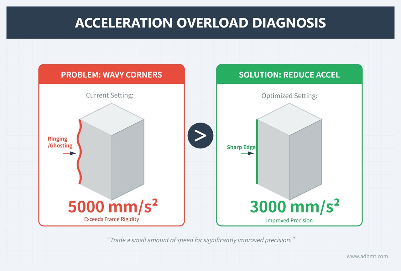
Issue 3: Jitter & Distortion
- Data Packet Loss: USB cables longer than 5 meters or with poor shielding can cause transmission disruptions, resulting in the machine pausing or moving erratically. For industrial environments, always use an Ethernet connection for stable data transfer.
- Acceleration Overload: If wavy patterns appear at corners, the software acceleration setting likely exceeds the frame’s rigidity limit. Reduce the idle-move acceleration from 5000mm/s² to about 3000mm/s² to trade a small amount of speed for improved precision.
Ⅶ. Industry-Specific Solutions
If general settings are the foundation, then industry-specific fine-tuning is the secret weapon that defines competitiveness. Since materials differ drastically in physical properties, trying to use one universal parameter set is inefficient and a major cause of high scrap rates. This chapter dives into front-line production to reveal software optimization strategies across metalworking, advertising, and precision electronics.
7.1 Metal Processing: Thick Plates and Tubes
In heavy industry, the software’s core challenge is balancing “maximum efficiency” with “equipment safety.”
Thick Plate Cutting: The Hidden Parameters of Leapfrog Technology The leapfrog technique synchronizes the X/Y and Z axes so the cutting head moves in a parabolic arc during idle travel — a major efficiency booster. However, when cutting carbon steel thicker than 20mm, chasing speed blindly can be disastrous.
- Smart Leapfrog Strategy: Thick plates tend to produce slag piles up to 3–5mm high during piercing. A low jump height (1mm) greatly increases the risk of the head colliding with the slag at high speed, which can fracture the ceramic body or damage sensors.
- Collision Prevention Logic: In software like CypCut or Lantek, always enable “Smart Leapfrog” or “Lift After Pierce” for thick plates. Set the Z-axis lift height to “plate thickness + 5mm” and activate “Obstacle Avoidance.” Although each lift adds about half a second per move, it can save a cutting head worth tens of thousands of yuan and prevent costly downtime.
Tube Processing: The ‘Five-Point Centering’ Method for Twisted Tubes In tube cutting, precision — not penetration — is the real challenge. Six-meter tubes often have twists or deformations, and the traditional four-point measurement (top, bottom, left, right) only calculates the geometric center, failing to correct rotational offset.
- 5-Point Centering: Specialized tube-cutting software like TubePro adds a fifth measurement point (typically taken after a 45° rotation). This extra data allows the algorithm to fit the true rotational ellipse center rather than an ideal circle, improving eccentricity compensation accuracy from ±0.5mm to ±0.05mm. The result: perfectly aligned through-holes without secondary reaming.
- Parameterized Intersect Cut Generation: There’s no need to model in SolidWorks — using the software’s built-in parametric tools, you can input the main tube diameter (ΦA) and branch tube diameter (ΦB) to automatically generate a saddle cut path. The system also calculates the variable-angle bevel based on wall thickness, ensuring a seamless, weld-ready fit.
7.2 Advertising & Craftwork: Acrylic and Wood
In this field, the essence of competition lies in aesthetic perfection. Well-optimized software parameters can eliminate the need for tedious post-polishing and sanding.
Acrylic: Frequency Is the Key to Transparency To achieve crystal-clear, flame-polished edges, it’s essential to differentiate between material types:
- Cast Acrylic (GS): Excellent heat resistance. Set the software to high frequency (10–20kHz) with low speed (<10mm/s). The high pulse overlap creates a continuous molten edge, producing a natural polishing effect.
- Extruded Acrylic (XT): Lower melting point and prone to bubbling. Use low frequency (2–5kHz) to allow cooling between pulses. Using cast-acrylic parameters here will whiten the cut edge or cause micro-cracks.
- Ramp Power Control: Enable this feature in LightBurn so that laser power dynamically adjusts with acceleration changes, preventing edge deformation or melting at sharp corners due to heat buildup.
Wood: The Art of Char-Free Cutting Burned edges are the greatest enemy of woodworking — they spoil aesthetics and interfere with later finishing.
- Gas Strategy: Never use oxygen (it promotes burning). Instead, use nitrogen or clean, high-pressure air assist.
- Path and Airflow: When designing the cutting layout, align the cutting direction with the exhaust airflow (downwind cutting) to prevent smoke from staining the edges.
- Layer Optimization: In LightBurn, enable “Optimize Cut Path” → “Order by Layer,” and always follow the “inner holes first” rule. This prevents defocusing or scorch marks caused by parts dropping out prematurely after the outer contour is cut. Pair this with masking tape on the surface for physical protection to achieve a perfectly clean, natural wood finish.
7.3 Electronic Precision Manufacturing
In the realm of micron-level fabrication, software must be capable of compensating for the minute imperfections of the physical world—turning the “impossible” into scalable mass production.
PCB Depaneling: Nonlinear Compensation via Vision Systems After reflow soldering, printed circuit boards (PCBs) often experience unpredictable thermal shrinkage and warping. Simple two-point fiducial correction is no longer sufficient for high-density boards.
- Multi-point Distortion Correction: Advanced software (such as LPKF CircuitMaster) employs a “global 4-point + local 2-point” vision alignment strategy. This approach not only corrects displacement and rotation but also compensates for trapezoidal distortion and nonlinear shrinkage rates.
- Dynamic Scaling: Based on real-time visual feedback, the software continuously fine-tunes the scale factor of the cutting path. As a result, every board has a uniquely optimized cutting trajectory, ensuring the kerf always falls precisely between pads—with deviations kept within 20 μm.

FPC Flexible Boards: The “Cold Processing” Strategy of UV Lasers Flexible printed circuits (FPCs) are highly sensitive to heat; fiber or CO₂ lasers can cause carbonization and short circuits. To avoid this, 355 nm ultraviolet (UV) lasers are used in combination with ultra-precise software control.
- Picosecond Pulses: Software regulates the pulse width down to the picosecond level, using high peak power to directly break molecular bonds rather than melt the material thermally.
- Multi-pass Micro-cutting: In CypCut, this is configured as a “multi-pass cutting” mode. Instead of trying to cut through in one pass, the laser rapidly makes around 20 passes, removing only 5 μm of material each time. This “peeling” approach prevents heat buildup, achieving carbonization-free edges (HAZ < 10 μm) and preserving the conductive performance of fine circuits.
VIII. Pitfall Avoidance Guide
On the road to mastering laser cutting, it’s not enough to scale the heights of technical skill—you must also learn to sidestep the deep pits along the way. Sometimes, avoiding a costly mistake can be just as valuable as achieving a technical breakthrough. Think of this chapter as your “mine detector” and “first-aid kit,” helping you identify and dismantle the most common traps that can swallow profits and patience alike.
8.1 Debunking the Three Big Myths
Misconceptions are more dangerous than operational errors because they can set you down a path of wasted effort from the very start. Let’s begin by clearing the fog of faulty thinking.
(1) The “All Software is the Same” Fallacy
This is one of the most destructive and widespread misunderstandings in the laser cutting field—akin to saying “all car engines are the same.” A high-quality industrial CAM software, enabled by its advanced intelligent nesting algorithms, can boost material utilization from 80% to 90% or more compared with basic software. For a factory consuming $100,000 in stainless steel sheets each month, that equates to over $100,000 in extra annual profit—enough to buy several more machines. Software’s impact on efficiency, cost, and final profit is decisive, not marginal.
(2) The “Bundled Software is Enough” Fallacy
Remember this harsh business truth: hardware sales are where equipment manufacturers make their money—not in software. To keep costs down, the software they ship is typically just enough to get the machine running. This is very often the single biggest bottleneck to your production efficiency.
Chances are, it lacks advanced features like path optimization, common-line cutting, fly cutting, or robust parameter library management—let alone seamless integration with ERP or MES systems. Upgrading to a specialized third-party solution (such as LightBurn or Lantek) can be the single most cost-effective investment you’ll ever make—unlocking up to 90% of your hardware’s untapped potential for less than 1% of its purchase cost.
(3) The Myth of “More Features = Better”
Complexity in features often works against operational efficiency. For a small creative studio that values rapidly turning ideas into reality, an industrial-grade package—requiring a specialized team, with a steep learning curve and overly elaborate production management modules—will not only consume resources unnecessarily but also slow creative momentum to a crawl. The best software is always the one that aligns perfectly with your core needs and day-to-day workflow—not necessarily the one boasting the longest list of features. In the software world, “just right” is far more valuable than “all-inclusive.”
8.2 The Software–Hardware Compatibility Nightmare
Software–hardware incompatibility is the number one culprit behind project delays, wasted investments, and operator burnout. Instead of frantically scouring forums after problems arise, act like a detective before you buy—use the following five-step method to stop this nightmare before it starts.
(1) Identify the “Heart” — Your Controller Model
This step is absolutely, unequivocally critical. The real “brain” of a laser cutter is its internal controller—such as the widely used Ruida, Trocen, GRBL, or proprietary systems from major brands. Any software you choose must explicitly list your machine’s exact controller model in its official compatibility documentation. This is the bedrock of compatibility—ignore it, and everything else is meaningless.
(2) Check Your Operating System (OS) and Version
This is a simple yet common oversight. Confirm that the software supports your computer’s operating system (Windows, macOS, Linux), and pay close attention to the exact version number. Sometimes the latest OS—like Windows 11—may conflict with software designed for older systems.
(3) Cross-verify — Ask Both “Matchmakers”
Before making a final decision, consult both the laser cutter seller and the software vendor—think of yourself as a meticulous matchmaker. Ask the machine seller: “Which third-party software have you officially tested and most recommend for this model?” Then ask the software vendor: “I have an XX brand, XX model, with an XX controller—will your software work with it 100% flawlessly?” Only proceed when both give a confident yes.
(4) Seek Real-World Proof — Tap into Communities
Vendor marketing can be embellished, but honest feedback from users worldwide is not. Post a clear, concise question on relevant forums (e.g., the LightBurn official forum or Reddit’s r/lasercutting): “Has anyone successfully run [chosen software] on [your machine model]? How was the experience? Any pitfalls?” Real-world user feedback is your best firewall against misleading promotions.
(5) Stay in Sync — Drivers & Firmware
Once connected successfully, make sure you’re running the latest stable version of the software—and check that your machine’s firmware is also the manufacturer-recommended latest. Every update typically fixes a host of potential compatibility bugs.
8.3 Common Troubleshooting Checklist: Quick Fixes for Issues Ranging from Poor Cut Quality to Software Errors
When problems do arise, don’t panic. Here’s a structured, quick-reference checklist designed to help you think like a professional engineer—troubleshooting issues methodically to pinpoint and resolve them effectively.
| Issue Category | Observable Symptoms | Possible Causes | Quick Solutions |
|---|---|---|---|
| Design File Issues | Cuts are open or incomplete Text appears garbled or missing Unwanted overlapping lines in the cut | 1. Vector paths are not closed. 2. Overlapping or duplicate lines. 3. Text not converted to vector outlines (curves/paths). | 1. Use your software’s “Close Path” or “Node Edit” functions to fix geometry. 2. Use “Remove Duplicates” or “Optimize” to clean up drawings. 3. Before exporting, convert all text to outlines or curves in your design software. |
| Software Settings/Errors | Software crashes or becomes unresponsive Cut dimensions don’t match the design Machine alarms for “Out of Bounds” or “Data Error” | 1. Outdated software version, bugs, or OS conflicts. 2. Mismatched unit settings between design and control software (mm vs inch). 3. Pulse settings in the software don’t match the machine motor’s resolution. 4. Communication issues (low-quality USB cable, driver errors, poor grounding). | 1. Update to the latest stable version and drivers. 2. Carefully unify unit settings across all software. 3. Recalibrate X/Y step-per-mm in the machine configuration. 4. Replace with a shielded, high-quality USB cable and ensure proper grounding for both PC and laser. |
| Cut Quality Problems | Material not cut through Rough edges or heavy dross Burn marks at corners Circles not perfectly round or distorted | 1. Power too low or speed too high. 2. Laser focus position incorrect (too high or low). 3. Auxiliary gas pressure too low or impure. 4. Nozzle dirty, damaged, or incorrectly positioned. 5. Corner optimization settings not enabled. 6. Uneven belt tension or mechanical backlash on X/Y axes. | 1. Increase power or slow speed; run small test cuts. 2. Refocus using the “ramp method” or machine guidelines. 3. Raise gas pressure; check purity. 4. Clean or replace nozzle; align and set correct height. 5. Enable “Corner Power” or similar setting in layer options. 6. With power off, tension belts evenly; set and test backlash compensation in software. |
Even the most seasoned engineers encounter problems—the real difference is how they respond. Professionals systematically document every issue. Starting today, keep a “Troubleshooting Log” (even a simple text file) where you record each problem, the fixes you tried, and what ultimately worked. Over time, this log will become your team’s most valuable and irreplaceable knowledge asset—far exceeding the usefulness of any generic guide.
Ⅸ. Frequently Asked Questions
1. What is the best software for beginners in laser cutting?
For beginners, user-friendly software with intuitive interfaces and supportive resources is essential. LightBurn and LaserGRBL are excellent choices for novices.
LightBurn offers extensive features tailored for laser cutting and engraving, while maintaining an accessible interface.
LaserGRBL is a free, open-source option often favored by hobbyists due to its simplicity and ease of use. Both options provide sufficient functionality to get started without a steep learning curve.
2. Can I use design software like Adobe Illustrator with any laser cutting machine?
Yes, design software like Adobe Illustrator can be used with most laser cutting machines, provided the software supports the required file formats for the laser cutter.
Adobe Illustrator can export files in formats such as AI, SVG, and DXF, which are commonly accepted by laser cutting software. However, it’s crucial to ensure compatibility between the design file and the laser cutter's control software. Tools like CorelDRAW and Inkscape are also popular for creating compatible vector designs for laser cutting.
3. How do I ensure my laser cutting software is compatible with my machine?
- Manufacturer’s Recommendations: Refer to your laser cutting machine's manufacturer guidelines for recommended or compatible software.
- File Format Support: Ensure the software can export or handle the file formats your machine requires (e.g., DXF, SVG, G-code).
- Hardware Integration: Verify that the software supports the communication protocols and controllers of your laser cutting machine.
- Trial Versions: Use trial versions of the software to test compatibility and functionality with your machine before committing to a purchase.
At the conclusion of the article, remember that whether you are optimizing workflows or upgrading your production line, the synergy between advanced software and reliable hardware is key. Explore our Single Table Fiber Laser Cutting Machine and Double Table Fiber Laser Cutting Machine to see which setup fits your operational demands, and feel free to contact us for tailored consultation and expert advice.


