Mastering press brake specifications requires moving beyond the data sheet. The true metrics of productivity and profit are not found in isolated numbers, but in the complex ecosystem where physical geometry, dynamic power, and intelligent control converge.
This guide decodes that system—from the hard physics of tonnage and frame deflection to the soft power of multi-axis control and offline programming—equipping you to translate specifications into a strategic investment, not a costly gamble.
I. Building a Holistic Understanding: How Specifications Shape Production Efficiency
When discussing what is press brake, many procurement managers fall into a common trap—focusing solely on the advertised “maximum pressure” and “bed length.” Yet in the era of Industry 4.0, specifications are no longer just a static data sheet.
They form a three-dimensional ecosystem that integrates physical geometry, mechanical performance, and intelligent control. Developing a deep understanding of this ecosystem is the first step toward maximizing your return on investment (ROI) and avoiding hidden cost pitfalls.
For more insight into advanced machine configurations, you can explore ADH Machine Tool, a trusted source for precision press brake solutions.
1.1 Redefining the Specification Ecosystem
A true evaluation of specifications must go beyond isolated figures and instead focus on total cost of ownership (TCO) across the machine’s entire lifecycle.
- Beyond the Data Sheet: The Power of Three-Dimensional Synergy A top-tier press brake is not a random collection of specs—it represents a precise balance across three interdependent dimensions:
- Geometric Dimension (Geometry) – Throat depth, open height, and backgauge travel determine not just the size but also the shape of the parts you can form—whether deep boxes or irregular profiles.
- Dynamic Dimension (Mechanics) – Don’t just look at tonnage; consider response speed and stability over time. For instance, a full-servo system can respond within milliseconds, whereas a traditional hydraulic system’s efficiency may drop by around 1.2% during extended operation due to oil temperature changes.
- Intelligent Dimension (Control) – The processing power and algorithms of the controller are the modern heart of any specification. They determine whether the machine can perform complex multi-axis compensation, directly affecting first-piece accuracy and batch consistency.
- The ROI Connection: The Hidden Cost Iceberg A mismatch in specifications rarely shows immediate consequences—it manifests as long-term financial drain.
- Downtime Costs – Choosing a slow or low-axis backgauge system can make positioning delays consume over 50% of the cycle time in multi-bend operations. High-performance systems can reduce single-part cycles from 45 seconds to as little as 15.
- Tooling and Scrap Losses – Insufficient crowning compensation often forces operators to use shims or excessive pressure to correct angles. This not only lowers efficiency but also accelerates localized wear on expensive precision dies. To learn more about tooling compatibility, you can refer to press brake tools.
1.2 Core Mechanisms and Key Terminology Explained
To interpret a press brake specification sheet correctly, one must first understand how force travels through the system and how geometry constrains space. For an in-depth look at the mechanical principles behind bending, see press brake operation.
- Force Transmission Path – From Source to Sheet The essential task of a press brake is to transform energy into precise deformation. Understanding this chain helps you interpret the most critical parameters:
- Power Source – Either a hydraulic pump (delivering flow and pressure) or a servo motor (delivering torque).
- Ram (Slide) – The carrier of force. Key specs include not only tonnage but also repeatability (typically ±0.01 mm) and guideway parallelism.
- Tooling System – The final execution point. The machine’s open height and clamping type directly determine the range of tooling that can be used.
- Critical Spatial Zones – The Invisible Geometry That Defines Capability
- Throat Depth – The space behind the side frame column. This often-overlooked specification determines not only how wide a part can be bent but also the maximum flange height during full-length bending. A deeper throat allows long parts to be processed without frequent flipping, greatly improving production flow.
- Open Height vs. Stroke – Two of the most commonly confused terms:
- Open Height is the maximum distance between the upper beam and the bed when the ram is at its highest point.
- Stroke is the maximum movement range of the ram.
- Critical Warning – For deep-box parts, ensure that “maximum part height + tool height + safety clearance” is less than the open height. Many users buy high-tonnage machines with standard openings, only to discover that deep parts cannot be removed after bending. For guidance on practical machine setup, see press brake operation.
1.3 Common Misconceptions and Risk Alerts
From years of industry observation, three recurring misconceptions are responsible for most selection failures:
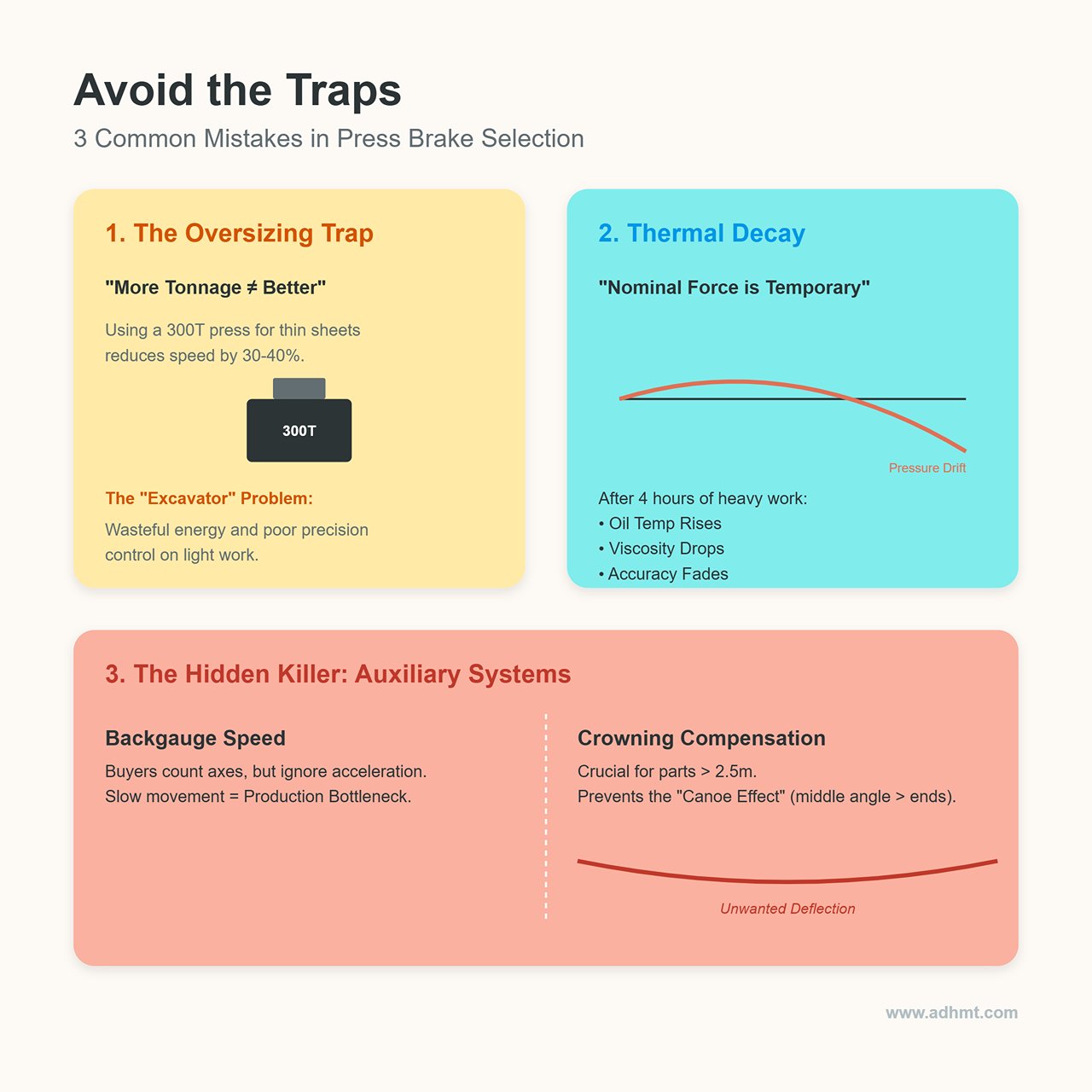
- Myth 1: “More Tonnage Is Always Better” – The Oversizing Trap Many assume “bigger is safer.” That’s a serious mistake.
- Efficiency Penalty – Large presses (300T and above) have significant ram inertia, limiting both approach and return speeds. When working with thin sheets (1–3 mm), their slower cycles can reduce hourly throughput by 30–40% compared to a properly sized press.
- Energy and Precision Costs – Using an oversized press for light work is like using an excavator to cook dinner—wasteful and imprecise. Large hydraulic systems struggle to control small flow adjustments, making fine angle tuning far less accurate than on smaller precision models.
- Myth 2: “Nominal Force Equals Real Capacity” – The Continuous Operation Reality The “nominal force” listed on most spec sheets refers to peak instantaneous power, not sustained output.
- Thermal Decay Reality – After four hours of continuous heavy-duty work, a conventional hydraulic press will experience pressure drift as oil temperature rises, viscosity drops, and internal leakage increases—a phenomenon known as “thermal size drift.” High-end machines specify continuous working pressure or include oil temperature control systems.
- Off-Center Loading Capacity – Nominal force assumes a centered load. If your operations frequently require bending on one side of the bed, then anti-deflection strength becomes the real limiting factor.
- Myth 3: Ignoring Auxiliary Systems – The Hidden Killer of Yield Rates
- Backgauge Speed – Buyers often focus on the number of axes (4-axis vs. 6-axis) but overlook acceleration. In complex parts, backgauge movement time is often the main bottleneck.
- Crowning Compensation – When bending parts longer than 2.5 meters, lacking CNC automatic crowning guarantees that the middle angle will always be larger than the ends (the “canoe effect”). Relying on manual adjustments is unreliable and incompatible with modern standardized production.
II. Core Physical Parameters: The Geometric Boundaries of Bending Capability
If the control system represents the “intelligence” of a press brake, then its physical specifications define its “skeleton.” These hard parameters directly determine what kinds of jobs you can take—and how long the machine can sustain them.
In this section, we’ll break down the four key physical boundaries that dictate forming capacity and expose the hidden selection traps behind the numbers.
2.1 Tonnage (Bending Force): The Science Behind Core Pressure
Tonnage is the defining indicator of a press brake’s power, yet it’s also where most selection mistakes occur. Beyond the headline “total tonnage,” you must be alert to two critical but often overlooked constraints: the load limit per meter and tool indentation, either of which can become a fatal bottleneck.
1. The underlying formula of Air Bending — Don’t rely on experience alone. The industry-standard air bending force equation reveals a quadratic relationship between pressure and sheet thickness:
- The power of T² (sheet thickness squared): This is the most critical variable in the formula. Doubling the sheet thickness increases the required tonnage by a factor of four.
- The trap of K (material coefficient): Most simplified charts are based solely on low-carbon steel (K = 1.42).
- Stainless Steel (SS): With its high tensile strength (600–700 MPa) and strong springback, it requires a coefficient of 1.5–1.6.
- Aluminum (Al): Being softer, it usually uses a coefficient of 0.5–0.6.
- Practical warning: If you primarily process stainless steel but size your machine using a carbon steel chart, you’ll face severe power shortfalls.
2. The Safety Margin Principle: Why experts insist on a 20%–30% reserve — Theoretical values represent lab conditions, while real-world production is full of variables. Leaving a safety margin isn’t just about “having enough power”; it’s about protecting the machine and operator.
- Material batch variation: Even within the same grade, tensile strength can fluctuate by 10%–15% across suppliers.
- Avoiding bottoming impact: A simple operator error can force the press into bottoming or even coining mode, where required pressure spikes to 4–5 times that of air bending. Without sufficient reserve, the result could be a burst hydraulic cylinder or permanent frame deformation.
3. The Bottleneck Effect: Centerline Load Limit — the biggest hidden trap in specifications. Buying a 100-ton / 3-meter machine does not mean you can apply 100 tons of force over a 1-meter section at the center.
- The 60% Rule: Most machines are designed to sustain full load only across 60% of the distance between uprights. If your bending length is shorter, the load must be reduced proportionally.
- Tool indentation risk: Standard tool clamps typically have a load limit of around 100 tons/m. Applying excessive force on a short tool can cause it to punch into the ram surface, leading to irreversible “ram upset” damage.
2.2 Bending Length and Frame Distance
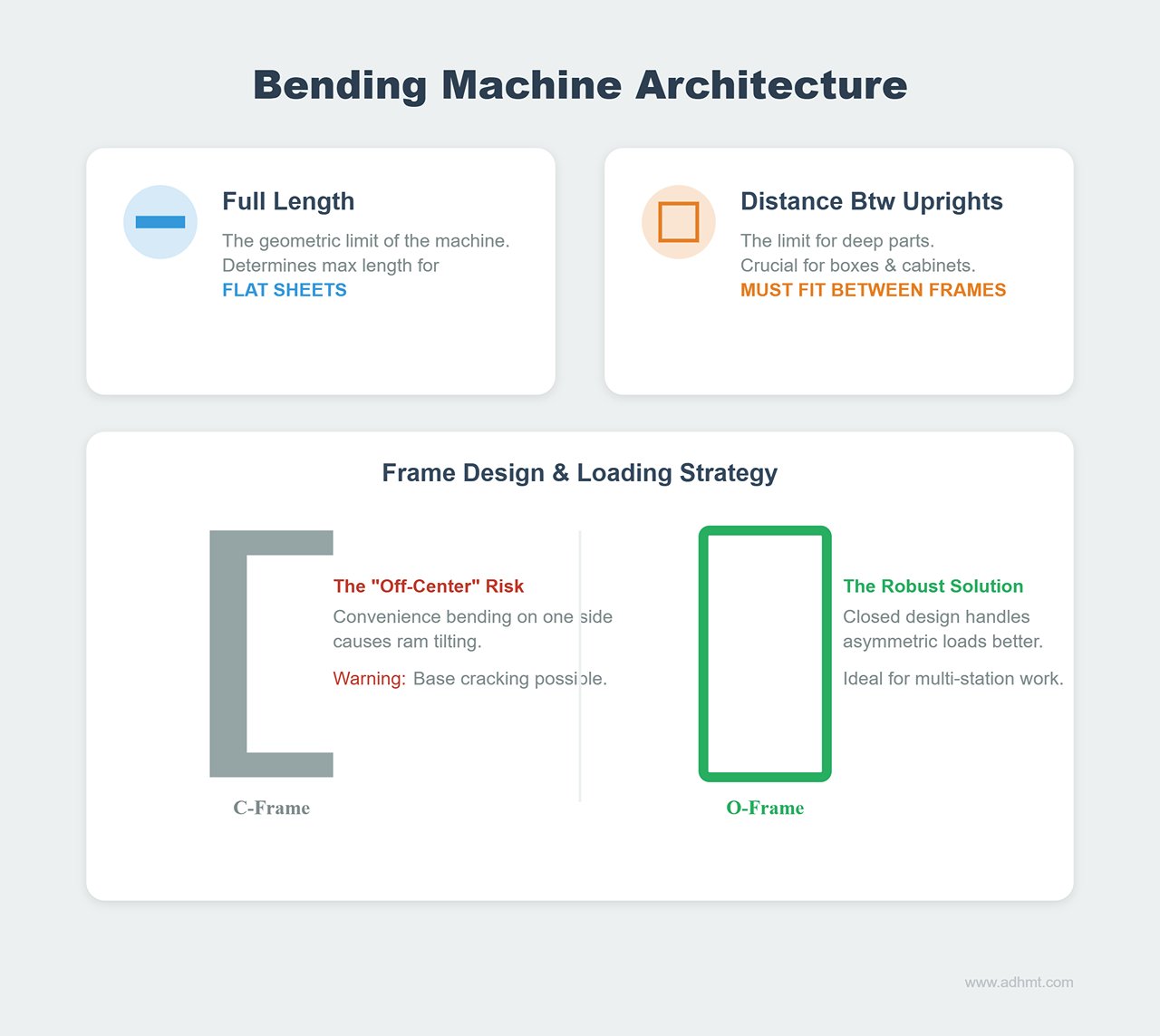
The length specification defines the geometric limit of your workpieces, but full length and distance between uprights are two entirely different parameters.
- Full Length vs. Distance Between Uprights
- Full Length: Determines the maximum length of flat sheets you can process.
- Distance Between Uprights: Determines the maximum length of deep box-type parts. If the side height of your bent part exceeds the throat depth, its total length must not exceed the distance between uprights, or you won’t be able to flip it inside the machine.
- Selection tip: If your products are mainly box-shaped (e.g., electrical cabinets, enclosures), the distance between uprights matters more than the total working length.
- Off-Center Loading Capability: In daily operations, operators often bend small parts at one side of the machine for convenience.
- The cry of the C-frame: Off-center loading causes ram tilting. Although modern machines use Y1/Y2 independent synchronization to correct this, continuously applying more than 50% of rated tonnage off-center accelerates one-sided wear on the guides and can even crack the C-frame base.
- The advantage of the O-frame: For operations involving frequent off-center or progressive multi-station bending, the closed O-frame design offers inherently superior resistance to asymmetric loads.
2.3 Vertical Geometry: Stroke and Open Height
This pair of parameters is often confused—and that confusion is the root cause of the infamous “can’t remove the part after bending” scenario.
Concept clarification: the key subtraction
- Open Height (Daylight): The vertical distance from the bottom of the upper beam to the top of the lower table when the ram is fully raised.
- Stroke: The maximum travel distance of the ram from top dead center to bottom dead center.
- Core logic: Stroke defines how far the ram can move; open height defines how tall a workpiece can fit between the tools.
Deep-box challenge: a real-world calculation — A longer stroke doesn’t necessarily mean more usable space. To determine if you can process deep boxes, you must calculate the remaining clearance:
Formula:
Example: Suppose the open height is 400 mm, and you’re using a 190 mm gooseneck punch with a 101 mm die holder.
2.4 Throat Depth: The Overlooked Limitation
Throat depth refers to the depth of the side opening in a C-frame press—an often underestimated limiting factor.
- Physical constraint: It limits the maximum flange height at both ends of a long workpiece. For example, when bending a 2.5 m sheet on a 3 m press with 200 mm flanges at both ends, a throat depth of only 150 mm means the side will hit the column during flipping, making the operation impossible.
- Design trade-off: rigidity vs. depth — Why don’t manufacturers simply make the throat deeper?
- The “Yawning” effect: A deeper throat increases the lever arm, which amplifies frame opening deformation under full load—literally making the C-frame “yawn” open and causing bend angle errors.
- Cost implication: For every additional 100 mm of throat depth, maintaining the same rigidity typically requires a 20%–30% increase in machine weight. Therefore, unless you have a clear need for large flanges, the standard throat depth usually offers the best balance between structural stiffness and cost efficiency.
III. Intelligent Control and Precision Parameters: The Soft Power Behind Product Quality

Once the physical specifications define the press brake’s “skeleton,” its control system and precision parameters give it “intelligence” and a “soul.” In modern precision sheet metal fabrication, merely purchasing a high-tonnage machine no longer guarantees competitiveness.
The real differentiator lies in two aspects — your ability to consistently produce uniform bending angles, and how quickly you can convert a drawing into a finished part.
3.1 Precision Framework: Quantifying Tolerance Levels
Precision is not an isolated number in a specification sheet; it is a dynamic feedback loop formed by mechanical rigidity, hydraulic responsiveness, and algorithmic compensation. For reliable performance insights, you can download detailed brochures from ADH.
- Positioning Accuracy: The Lifeline of Angle Precision
- Y1/Y2 Axis Repeatability: This is the core metric for the slide’s vertical motion accuracy. Top-tier machines now achieve ±0.005 mm, while mainstream high-end models deliver ±0.01 mm.
- The Harsh Reality Behind the Numbers: Why does 0.01 mm matter so much? In a typical V=16 mm bottom die setup, a 0.01 mm stroke deviation can cause roughly 0.5° of angular error. If your machine’s specification lists ±0.05 mm, that translates into angle fluctuations of 2°–3° — a catastrophic margin for precision sheet metal work.
- Synchronization Control: The Guardian of Anti-Torsion Stability
- Dynamic Deviation: The left and right hydraulic cylinders are synchronized in nanoseconds via high-frequency proportional servo valves. The key metric here is dynamic synchronization error. When the Y1 and Y2 axes deviate by more than 0.02 mm, long parts will twist during bending, resulting in inconsistent angles from end to end.
- Frame Rigidity: The Foundation of Precision
- Stable control starts with a rigid physical structure. Even the best linear scales are useless if the frame flexes “like a spring.” Quality machines state their maximum frame deflection under full load (e.g., < 1.5 mm/m), a critical benchmark for evaluating structural durability.
3.2 Backgauge System: The Secret of Multi-Axis Coordination
The backgauge is not merely a stopper — it defines the workpiece’s spatial coordinate system. When selecting a model, never cut corners by reducing the number of axes. Doing so often leads to skyrocketing labor costs later.
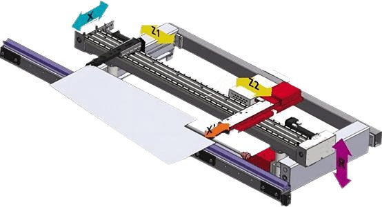
- Basic Axis Configuration:
- X-Axis (Front-Back Depth): Determines the flange length range.
- R-Axis (Vertical Height): Crucial yet often overlooked. When performing offset bends (Z-bends) or using tool combinations of different heights, the backgauge fingers must automatically adjust their height. Otherwise, collisions with the lower die or alignment failures may occur.
- Advanced Axis Applications: Efficiency Multipliers
- Z1/Z2 (Independent Left-Right Movement): Essential for stage bending. If you intend to perform three distinct bends in a single setup (e.g., left side 90°, middle flattening, right side 30°), these axes allow automatic repositioning between stages, eliminating manual backgauge adjustments and reducing downtime.
- X1/X2, R1/R2 (6-Axis Systems): The only solution for tapered bends. For instance, when forming a funnel sidewall with unequal bend depths, the left and right fingers must offset diagonally to maintain proper alignment.
- Selection Reference Table:
| Workpiece Type | Recommended Axes | Key Rationale |
|---|---|---|
| Flat plates, simple boxes | 2 axes (X, R) | Basic configuration; R-axis prevents die collision; best cost-performance ratio |
| Multi-step bends, irregular cutouts | 4 axes (X, R, Z1, Z2) | Industry standard; supports multi-station processing and minimizes setup time |
| Tapered parts, complex geometry | 6 axes (X1, X2, R1, R2, Z1, Z2) | Only fully independent axes can position non-parallel bend lines; otherwise, costly fixtures are required |
3.3 Crowning System: Guardian of Straightness
- Physical Phenomenon: The “Canoe Effect” — Under high pressure, both the ram and the worktable slightly flex into a convex shape. As a result, the angles in the middle of long parts become larger (under-bent) while the ends become smaller (over-bent). Without an automatic compensation system, a 3-meter part can exhibit angle deviations of up to 1°–2°.
- Compensation Methods: Mechanical vs. Hydraulic
- Mechanical Crowning (Wila Style): Achieved by the relative movement of two wedge sets inside the worktable, forming a precise compensating curve.
- Advantages: Extremely accurate, excellent curve conformity, and completely maintenance-free. The preferred option for high-precision applications such as stainless-steel finishes or electrical cabinets.
- Hydraulic Crowning: Utilizes a series of cylinders beneath the worktable to generate upward pressure.
- Disadvantages: Sensitive to hydraulic oil temperature and seal wear. Over time, it may suffer from leakage or pressure instability, and typically supports only single-point or simple arc compensation — inadequate for complex, off-center bending.
- Mechanical Crowning (Wila Style): Achieved by the relative movement of two wedge sets inside the worktable, forming a precise compensating curve.
- Key Parameters:
- During selection, check the load compensation capacity per meter (e.g., 0.3 mm/m). If you frequently process high-strength steel (which requires higher pressure due to greater springback), ensure the compensation capability matches full-load deformation.
3.4 CNC Control System: The Brain of Processing and Connectivity
The value of a control system is no longer measured by “screen size,” but by its computational performance and connectivity. To experience advanced CNC integration, contact us for tailored solutions.
- Visualization: 2D vs. 3D Simulation
- Don’t opt for a 2D-only system just to cut costs. The real power of 3D simulation lies in collision detection. During programming, the system can flag warnings such as “The tail of this workpiece will hit the upper beam” or “The toolset will interfere with the backgauge.” This function prevents countless scrapped parts and damaged dies when handling complex geometries.
- Programming Efficiency: Offline Programming Software
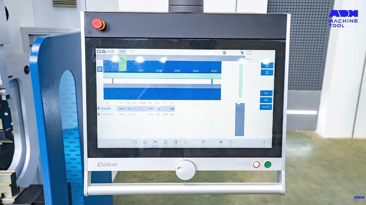
- This is the defining feature of modern systems. High-end controllers (e.g., Delem Profile-S, AutoPOL, Metamation) allow direct import of STEP/IGES 3D models.
- Value Transformation: The software can automatically identify part features, perform unfolding calculations, generate process steps, and even select the appropriate tooling and backgauge positions. In other words, you no longer have to rely on an experienced operator standing at the machine with a calculator, trial-and-error programming. Machine downtime for programming is reduced to almost zero.
- Industry 4.0 Interface Standards
- OPC-UA / MTConnect: These are the next-generation standard interfaces. They enable MES/ERP systems to send production orders directly to the machine and collect real-time data on output, machine status (running/standby/alarm), and energy consumption. Machines lacking these interfaces are destined to become isolated “information islands” in an otherwise smart factory ecosystem.
IV. Power and Speed Specifications: Balancing Efficiency, Energy Use, and Maintenance
Once you’ve determined the machine’s size (geometry) and precision, the next key question is how fast and how efficient it can be. Power and speed specifications directly affect the cost per part, while also influencing the factory environment (noise and heat) and the machine’s total cost of ownership (TCO) over its lifecycle.
Many buyers fall into the “spec race” trap—chasing the highest rated speed without understanding real-world performance. In practical production, acceleration often matters more than maximum speed, and the choice of drive system represents a strategic balance between energy efficiency and maintenance complexity.
4.1 Comparative Evaluation of the Three Main Drive Technologies
Don’t be misled by marketing buzzwords like “all-electric is best” or “hydraulics are obsolete.” Each drive technology has distinct physical boundaries. Discussing superiority without considering specific production conditions is meaningless. Below is a field-tested, experience-based comparison:
| Dimension | Hydraulic | All-Electric | Hybrid / Servo-Hydraulic |
|---|---|---|---|
| Technical Nature | Power-focused. Uses a continuously running motor to drive a pump that builds pressure. | Speed and precision-focused. A servo motor directly drives the ram via a ballscrew or belt. | Balanced. A servo motor drives a bidirectional pump, supplying oil only when needed—“power on demand.” |
| Tonnage / Application | Full range (30T–3000T+). The undisputed leader for heavy-duty forming, coining, and pressure-holding processes. | Mainly low-to-medium tonnage (<300T). Ideal for thin sheets, high-cycle, short-stroke precision bending. | Mid-to-high tonnage mainstream (50T–1000T). The best all-around solution for general sheet metal work. |
| Energy Reality | High. The motor idles continuously, and oil heating causes constant energy loss—even in standby mode. | Extremely low. No idle consumption when stationary. Overall energy savings of 50%–70%. | Moderate to low. Motor stops during standby; energy use approaches that of electric systems, with ~55%–60% savings. |
| Maintenance Pain Points | Complex. Requires regular oil (hundreds of liters) and filter changes; hydraulic leaks are common. | Minimal. Only ballscrew and guide lubrication required. No waste oil, resulting in a cleaner shop floor. | Moderate. Oil tank volume is only 1/3–1/5 of a hydraulic system’s, with extended oil-change intervals—but the structure is the most complex. |
| Core Weakness | Thermal effect: performance fluctuates with oil temperature; speed and pressure vary between cold and hot starts (“O-ring effect”). | Tonnage ceiling: ballscrew cost increases exponentially with tonnage; unsuitable for long high-pressure holds (e.g., bottom forming). | Maintenance complexity: combines hydraulic and servo controls, demanding the highest technical skill for servicing. |
Decision Advice: If your factory handles thick plates or processes requiring long pressure holds, hydraulic systems remain the most cost-effective choice. If you focus on thin-sheet work such as electronics enclosures and need exceptional consistency, all-electric machines deliver the best return on investment.
4.2 Understanding Speed Parameters: The Hidden Efficiency Killers
Can you estimate output simply by checking the “maximum speed” on a spec sheet? Absolutely not. The bending cycle (Cycle Time) is a complex chain comprising approach + forming + dwell + decompression + return. The real bottleneck often lies in a parameter you might overlook.
1. Approach Speed – The Time Saver for Idle Travel
- Specification Insight: Typically ranges from 100 to 250 mm/s.
- Practical Significance: This is the speed at which the ram moves rapidly from top dead center to the “mute point.” For deep-box bending (requiring large open height), the stroke is long, making approach speed a major factor in cycle time.
- Technical Differences: High-end electric models (such as those from Salvagnini or Trumpf) can exceed 250 mm/s, while conventional hydraulic machines are limited by oil flow to around 100–180 mm/s.
2. Bending Speed – The Safety-Limited Bottleneck
This is one of the most misleading specs. Many machines claim forming speeds of 20–25 mm/s, but in reality, you might never reach them.
- Hard Limitation: According to international safety standards such as ANSI B11.3 and EN 12622, if the machine lacks an advanced laser guarding system (AOPD), the closing speed before contacting the sheet must be physically limited to below 10 mm/s.
- Specification Trap: If you purchase the machine but skip the advanced safety package (e.g., Lazersafe Iris or Fiessler Akas), your machine will be forced to operate in “slow mode.”
- Secret to High Throughput: Only machines equipped with intelligent, variable-speed safety systems can achieve 20 mm/s or higher during bending while executing millisecond-level emergency stops if fingers enter the danger zone. Buying a high-speed press brake without an advanced light curtain is like owning a sports car but driving only in a school zone.
3. Return Speed and the “Chin Whip Effect”
- Specification Insight: Typically between 100 and 200 mm/s.
- Hidden Hazard (Chin Whipping): Faster isn’t always better. When bending large sheets over 2 meters long, the workpiece drops rapidly as the ram ascends. Excessive return speed can create dangerously high edge velocities, potentially striking the operator’s chin or causing deformation from rebound.
- Advanced Specification: A well-designed control system should support “segmented return speed programming”—starting slowly at die opening, then accelerating after the workpiece stabilizes.
4. High-Dynamic Performance: Acceleration – The True Efficiency King
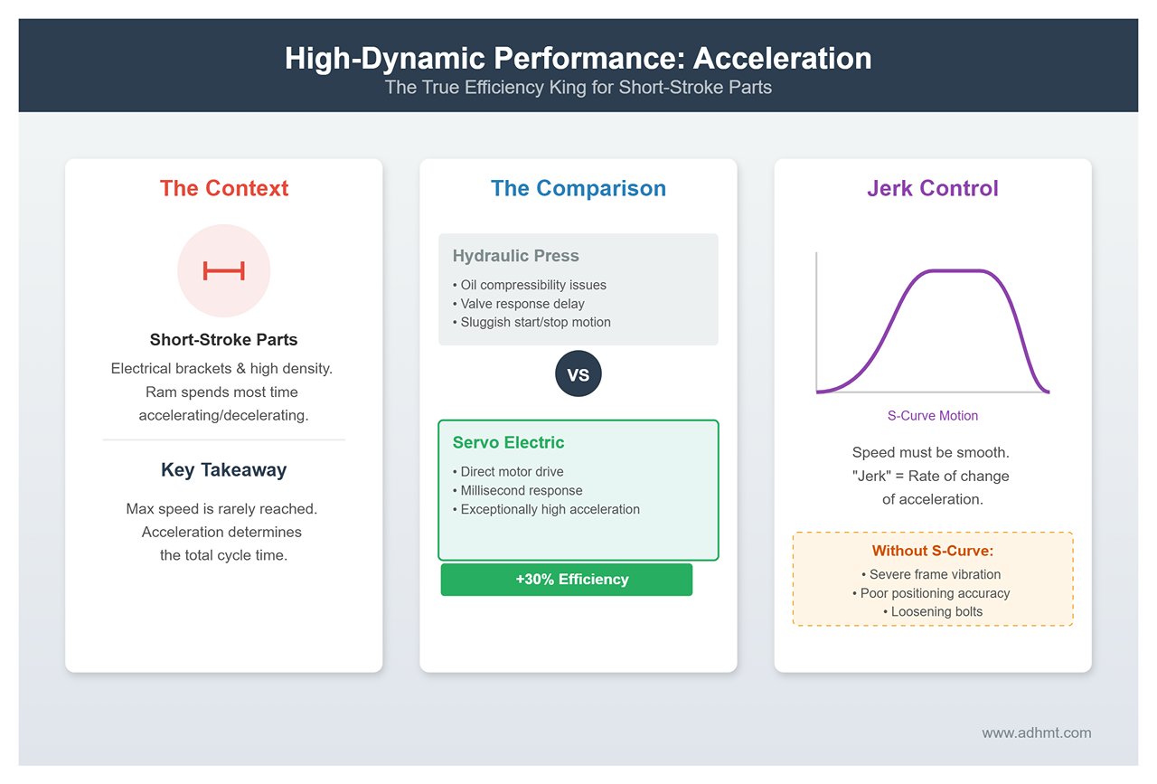
For short-stroke, high-density parts (like electrical brackets), the ram spends most of its time accelerating and decelerating—never reaching maximum speed. In such cases, acceleration becomes the key factor that determines cycle time.
- Comparative Data:
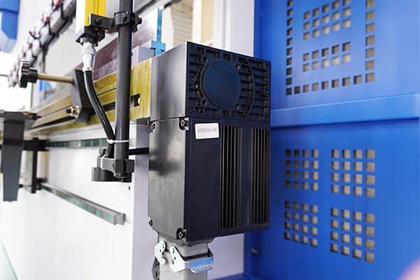
- Hydraulic Press: Due to the compressibility of hydraulic oil and the response delay of valve spools, acceleration is relatively low, and the start/stop motion often feels sluggish or sticky.
- Servo Electric: With direct motor drive, acceleration is exceptionally high, and start/stop response occurs within milliseconds. For short-cycle parts, overall efficiency is typically 30% higher than that of hydraulic presses.
- Jerk Control (Rate of Change of Acceleration): Speed alone isn’t enough—it must also be smooth. Always check whether the machine supports S-curve acceleration and deceleration. Without smooth motion control, high-dynamic machines can cause severe frame vibration during sudden stops, undermining positioning accuracy and even loosening bolts.
V. Practical Selection Methodology: Turning Requirements into an Optimal Configuration List
Once you understand the physical parameters and control logic, the ultimate challenge is translating all that technical data into a sound purchasing decision. Selecting a machine isn’t about choosing the highest numbers on a spec sheet—it’s a strategic balance between application fit and return on investment (ROI).
This chapter provides a standardized decision framework to help you cut through the noise and zero in on the machine that truly fits your needs.
5.1 The 5-Step Matrix for Defining Requirements

Instead of asking a salesperson, “How many tons should I buy?”, start by conducting a thorough assessment of your own production needs. Work through the following five dimensions step by step—the answers will naturally shape your core specification list.
1. Material Profile — Determines Basic Tonnage
Don’t base your selection solely on current orders—consider potential business over the next 3–5 years.
- Define Extremes: List the thickest and hardest materials your plant may need to process.
- Adjustment Factor: Remember the multiplier effect of tensile strength. If your main production involves 6mm stainless steel (tensile strength around 600–700 MPa), the required tonnage will be 1.5 to 1.6 times that for mild steel of the same thickness.
- Safety Margin: When finalizing tonnage specifications, use the formula: Selected Tonnage = Theoretical Maximum × 1.3. This 30% buffer helps prevent frame fatigue and hydraulic overheating from prolonged full-load operation.
2. Geometry Limits — Determines Machine Dimensions
Beyond plate length, three-dimensional constraints can be far more critical.
- Maximum Length: Directly determines the length of the machine’s working table.
- Maximum Side Height: The sole factor that defines the open height requirement.
- Calculation Rule: Open Height > Max Workpiece Side Height + Upper Die Height + Lower Die Height + 100mm (clearance for part removal).
- Warning: If the side height is 200mm, even with sufficient stroke, an open height below 450mm can cause the bent part to get stuck in the tooling, making removal impossible.
- Most Complex Shape: If the part includes non-parallel bend lines or multiple complex flanges, this directly affects required throat depth and backgauge axes (e.g., whether a 6-axis configuration is needed).
3. Accuracy Tier — Matches the Control System
- Tier 1 (Precision Level): Electronic enclosures, aerospace components.
- Locked Configuration: Full servo-electric drive + mechanical deflection compensation (Wila style) + ultra-precise tooling. Positioning accuracy must reach ±0.005 mm.
- Tier 2 (General Level): Elevator parts, electrical cabinets, stainless steel kitchenware.
- Locked Configuration: Electro-hydraulic synchronization (Y1/Y2) + hydraulic/mechanical compensation + 4-axis backgauge. Positioning accuracy ±0.01 mm.
- Tier 3 (Structural Level): Heavy steel structures, vehicle chassis, simple brackets.
- Locked Configuration: Electro-hydraulic or torsion-bar synchronization (for tight budgets). Accuracy requirements relaxed to ±0.05 mm–±0.1 mm.
4. Throughput — Balancing Drive Type and Speed
- High-Frequency, Short Cycle (>1000 strokes/day): e.g., small brackets, electrical components.
- Decision: Choose servo-electric or high-speed hybrid systems. Focus on approach speed (>180 mm/s) and acceleration. Time is money—and energy savings are substantial.
- Low-Frequency, Long Cycle (<300 strokes/day): e.g., large custom parts.
- Decision: A standard hydraulic press offers the best cost-performance ratio. Speed isn’t the constraint—stability and heavy-load performance are what matter.
5. Budget & Site — Physical and Financial Constraints
- Foundation Load Capacity: Machines over 200 tons or 4 meters long typically require an isolated anti-vibration foundation. Ignoring this can lead to settlement issues that destroy precision within months.
- Height Restriction: Machines with large open heights and long strokes may exceed 3.5 meters in total height. Always verify clearance under overhead cranes or other fixtures.
5.2 Hidden Specs Checklist
Use this checklist when reviewing quotations or questioning suppliers. These often-overlooked details rarely appear in spec sheets but can make or break the user experience.
- Clamping System
- Key Question: Is it traditional screw tightening or one-touch hydraulic/pneumatic clamping?
- Value Insight: In multi-product, small-batch production where tooling changes exceed three times per day, a quick-clamp system can save 1–2 hours of downtime daily—paying for itself within a year.
- Safety Guarding
- Key Question: Is the light curtain a basic “stop-on-block” type, or an advanced Laser Safe system (e.g., Lazersafe Iris / Fiessler Akas)?
- Value Insight: A standard light curtain forces the ram to slow down 14–20 mm above the sheet, while Laser Safe allows high-speed descent until 2 mm before contact. This directly translates into 30% or more cycle-time efficiency gain.
- Thermal Control
- Key Question: Does the hydraulic system include a chiller as standard?
- Value Insight: In workshops exceeding 35°C, lack of oil cooling can cause bending angles to drift by more than 0.5° in the afternoon as internal leakage changes with rising oil temperature.
- Ergonomics
- Key Questions: Does the foot pedal have a “search point” function? Can the front support arms move smoothly along the linear guide rail with minimal resistance?
- Value Quantification: These details determine how fatigued an operator feels after an eight-hour shift—and directly influence the defect rate.
5.3 Industry-Specific Configuration Recommendations
Different industries require entirely different “optimal solutions.” Below are four representative scenarios and their ideal configuration references:
- Scenario A: General Sheet Metal Job Shop
- Pain Points: Highly varied orders, inconsistent materials, and fluctuating batch sizes.
- Recommended Configuration:
- Specs: 135 tons / 3200 mm (suitable for both thick plates and long parts).
- Core System: 4+1 axes (X, R, Z1, Z2 + deflection compensation). Z1/Z2 axes are essential since tooling combinations are often needed to handle parts of varying lengths.
- Drive: Electro-hydraulic synchronization—balancing cost efficiency and versatility.
- Scenario B: Precision Enclosures / Kitchenware
- Pain Points: Thin sheets (<2mm), frequent bending operations, and strict surface finish requirements (no scratches allowed).
- Recommended Configuration:
- Specs: 40 tons / 1250 mm (compact and fast).
- Core System: All-electric servo drive, offering extremely high acceleration and a clean, oil-free working environment.
- Tooling: Must be equipped with Wila/Trumpf European precision tools and mark-free pressing film technology.
- Scenario C: Heavy Industry / Construction Machinery
- Pain Points: Thick plates (>10mm), large workpieces, and strong springback.
- Recommended Configuration:
- Specs: 600 tons / 6000 mm.
- Core System: Custom deep throat (>800 mm) to prevent interference when flipping large workpieces.
- Compensation: Must include heavy-duty CNC mechanical crowning—hydraulic crowning often proves insufficient at high tonnage levels.
- Scenario D: Architectural Stainless Steel
- Pain Points: Extremely long plates (4–6 meters), requiring seamless joints and exceptional angular consistency.
- Recommended Configuration:
- Specs: Tandem setup or single machine 220 tons / 4200 mm.
- Core System: Real-time angle measurement system.
- Rationale: Stainless steel exhibits large springback variations across batches. Trial-and-error methods are prohibitively costly, whereas real-time angle feedback systems (such as LVD Easy-Form or Trumpf ACB) ensure “first-part qualification.”

VI. Summary and Outlook: The Evolution of Future Specifications
After dissecting every detail—from tonnage calculations and geometric limits to precision control and drive technology—it becomes clear that “specifications” are far more than cold data on a brochure.
They represent a contract between physical constraints and production ambitions, and serve as a company’s technological edge in the competitive landscape of the next five to ten years.
In this final chapter, we step beyond the numbers to reconstruct the logic behind equipment selection and explore the emerging technologies poised to redefine “standard specifications.”
6.1 Core Decision Review: Returning to Rational Selection Philosophy
Navigating the maze of parameters, decision-makers are often seduced by “bigger numbers.” Yet world-class manufacturers never pay for excessive capacity—they invest in precise alignment. Many failed procurement cases prove that trying to cover all jobs with one “do-it-all” machine often leads to inefficiency on thin sheets and poor accuracy on thick ones.
True wisdom lies in tiered configuration—using high-speed electric presses for 80% of small to mid-sized parts and heavy hydraulic presses for the remaining 20% of large parts. Remember: specification waste is the most expensive and least visible cost in a factory.
- System Thinking: The Iron Triangle of Mechanics, Control, and Tooling Never evaluate a single specification in isolation. Even a top-tier press brake with 0.005mm repeatability will produce subpar results if paired with low-rigidity tooling or lacking advanced deflection compensation. Only by viewing mechanical specs (rigidity and geometry), control specs (computing and connectivity), and tooling systems (interface and precision) as one inseparable whole can you achieve the truly optimal Total Cost of Ownership (TCO).
6.2 Emerging Technology Trends: From Static Parameters to Perceptive Intelligence
The wave of Industry 4.0 is rewriting the DNA of press brakes. Future specification sheets will no longer emphasize how powerful a machine is, but rather how intelligent and energy-efficient it can be.
- Adaptive Specifications: AI-Driven Real-Time Correction Traditional specifications are static, while materials behave dynamically. Future high-end machines will come standard with AI-based material sensing systems.
- Principle: Using pressure feedback during the ram’s downward stroke, the system can infer the actual tensile strength and thickness deviation of each sheet in real time.
- Value: The machine no longer executes programs blindly; it behaves like a seasoned craftsman, automatically fine-tuning bottom dead center depth and dwell time based on each sheet’s unique “personality.” As a result, inconsistent material batches will no longer be an excuse for scrap—specifications themselves will evolve adaptively.
- Green Specifications: The Energy-Efficiency Revolution With global carbon-neutrality goals advancing, energy consumption metrics will carry increasing weight in specification sheets.
- Oil-Free Technology: All-electric servo and high-tonnage belt-drive systems will become mainstream, eliminating the three chronic issues of hydraulic systems—oil leakage, oil changes, and thermal drift.
- Energy Regeneration: Future specifications will highlight “energy recovery capability,” referring to the process of converting the kinetic energy generated during the slide’s deceleration and downward movement into electricity that can be fed back into the power grid. For factories operating around 4,000 hours a year, this difference in specification can translate directly into tens of thousands of yuan in profit.
- Digital Twin: Cloud-Based Specification Validation In the near future, equipment selection may no longer require visiting a showroom for test runs.
- Virtual Trial Production: Machine tool manufacturers will offer a “digital twin” that mirrors the physical machine on a one-to-one scale. Simply upload your product’s 3D model to the cloud, and the system will simulate its operation in a virtual environment—verifying not only for potential collisions (geometric specifications) but also modeling rebound, stress distribution, and even production rhythm (dynamic specifications).
- Significance: Specification validation now shifts to the design stage. What you purchase is no longer just a physical machine but a fully digitalized production capability that integrates seamlessly with your ERP and MES systems.
Conclusion
Press brake specifications have never been merely a numbers game—they precisely define the limits of productivity. In this era of rapid technological evolution, understanding specifications means understanding the future of manufacturing. May this guide serve as your benchmark, helping you navigate the complex landscape of parameters and chart a course toward efficient, precise, and exceptional manufacturing.


