I. What Is Metal Manufacturing
Metal manufacturing involves the transformation of metal into parts using a series of machines and tools. The process involves cutting, bending, and welding the metal. Once the parts are designed, they are processed using various machines such as a laser cutting machine, CNC press brake, turret press, and welding machine. In many precision sheet metal shops, this bending stage is often completed by automated CNC Press Brake Forming processes to ensure consistent quality and repeatability. To explore high-precision bending equipment, you can view our CNC Press Brake selection for detailed specifications.
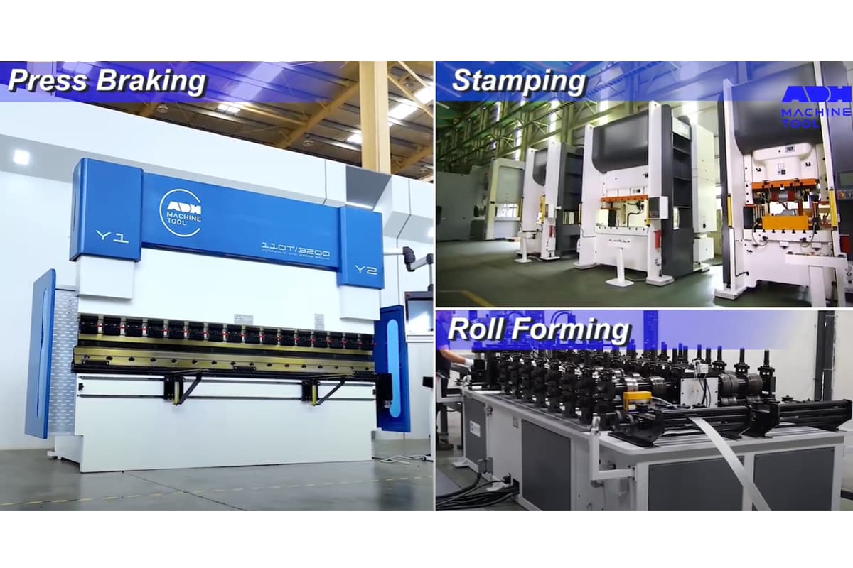
These machines are suitable for small-batch parts manufacturing in sheet metal fabrication project. In the manufacturing industry, metal forming methods mainly include press braking, stamping, and roll forming. For readers interested in understanding how press braking compares to stamping in industrial contexts, you can learn more from Press Brake vs Stamping: Key Differences.
This article aims to introduce the differences, advantages, and disadvantages of these types of metal-forming processes. It will also highlight the factors to consider when selecting metal-forming methods.
The metal manufacturing process selected will vary depending on the type of products needed. The following is a detailed introduction to different metal manufacturing methods. Let's watch the video first.
II. What Is Roll Forming
Roll forming is a metal forming process where metal sheets or rolls are bent into longitudinal and uniform profiles with the assistance of specialized tools. Roll forming progressively bends sheet metal into the desired shape. The raw materials used for roll forming are metal flat plates or metal rolls.
Unlike other metal forming processes, roll forming is a cold forming process that doesn't require high-temperature equipment to heat the metal. The bending radius in roll forming is determined by the material characteristics of the metal plate and can complete 180-degree bending. This process provides strict tolerances for complex profiles and can integrate welding, laser cutting, and other secondary processing into a production line.
The roll forming machine is available in two types: a single task roll forming machine that gradually bends each specific section by connecting the profile with the spindle, and a standard roll forming machine that is easy to operate, with the operator being able to remove the spindle easily. Besides these two types, there are parallel machines that can be equipped with a variety of rolling tools.

2.1 Advantages of Roll Forming
Roll forming technology is ideal for mass manufacturing and complex parts manufacturing due to its gradual metal bending process, which can produce strict tolerances. Even complex profiles produced through roll forming will be highly standard and accurate.
Roll forming is suitable for mass production, as the length of the material is not limited by the machine. The strength of the material can be improved after spring back by coiling the metal plates and feeding them into the machine.
Roll forming machines can produce complex cross-sections and bends, with strict and repeatable tolerances. The size of the produced parts is very accurate, with uniform and glossy surfaces.
Roll forming is capable of handling high-strength metals without breaking. There is no limit to the length of parts formed by roll forming, and the maintenance cost of rolling machine tools is low. Roll forming produces less waste and uses fewer materials to produce stronger parts.
For more detailed technical data and specifications, you can download our brochures to explore roll forming capabilities in various industries.
2.2 Disadvantages of Roll Forming
Roll forming is more suited for the mass production of complex parts, and the cost of small-batch production using roll forming can be high. The roll forming tooling used in roll forming is complex and expensive, and changing the tooling can add to the cost. Roll forming may cause the port of the part to expand outward, which can be a disadvantage in certain applications.
2.3 Key Steps in the Roll Forming Process
Coil Loading and Preparation
The process begins by loading a metal coil, typically made of steel, aluminum, or similar materials, onto a decoiler. The strip is then straightened to remove any defects, preparing it for the forming operations.
Progressive Shaping
Each set of rolls gradually shapes the strip into its final profile. This incremental bending minimizes stress and deformation, producing a consistent cross-sectional profile.
Profile Straightening and Cutting
Once the desired shape is achieved, the profile may require straightening to correct any deviations caused during forming. The final step involves cutting the product to specified lengths using a cut-off press, ensuring the pieces meet exacting specifications.
2.4 Practical Application Examples
(1) Solar Power Industry:
Example: Roll forming is used to produce the structural components that hold solar panels in place. These components need to be durable and precisely shaped to ensure the panels are positioned correctly for maximum efficiency.
(2) Commercial Food Storage:
Example: Roll forming is employed to create the complex profiles and tight tolerances required for commercial refrigerators and freezers. This ensures that the storage units are both functional and aesthetically pleasing.
(3) Transportation Industry:
Example: Roll forming is used to manufacture long, uniform components for train cars and cargo trailers. This process is ideal for producing the large, consistent parts needed in these applications.
III. What Is Metal Stamping

Metal stamping is the forming process of metal using a large tonnage stamping machine. The process involves stamping, bending, punching, flanging, and pressing. Custom tools and machines are used to shape the workpiece into the desired pattern. Stamping is suitable for mass production of parts, with simple parts requiring only one stroke, while complex parts may require multiple strokes.
3.1 Design and Tooling Preparation
The stamping process starts with design and engineering, crucial for shaping metal accurately. This phase involves using CAD or CAM software. Engineers consider material properties to ensure metal flow and support desired features. The design includes creating dies, essential for accurate results.
3.2 Material Preparation
Choosing the right material is crucial for a successful stamping process. Metal sheets or coils are selected based on mechanical properties like strength and ductility, corrosion resistance, and cost. The material must suit the stamping operations and the final part's use. Proper preparation ensures the metal will respond well to stamping forces and not crack or deform.
3.3 Feeding and Stamping Operations
Metal sheets or coils are fed into a stamping press using an automated mechanism, ensuring a continuous supply of material for shaping. The press applies force through the dies to shape the metal. Stamping operations include blanking (cutting shapes), bending (creating angles or curves), coining (adding details), and punching (making holes or cutouts). Each operation requires specific tooling and setup.
3.4 Quality Control
After stamping, quality control ensures each part meets specified standards. Continuous monitoring checks dimensions, surface finish, and integrity. Prompt corrections reduce waste and maintain consistent quality, crucial in precision industries like automotive and aerospace manufacturing.
3.5 Advantages of Stamping
Stamping operations are simple, easy to use, and cost-effective. The stamping process is fast, and the requirements for operators are not high.
3.6 Disadvantages of Stamping
If the workpiece produced by the stamping machine is long, it may leave tool scratches. After stamping, the workpiece may sustain some damage. Stamping only deforms the metal through the tools, which can be a disadvantage for certain applications.
When a workpiece requires different lengths, it needs different stamping dies, which can increase production costs. Therefore, stamping is more suitable for small batch production.
3.7 Practical Application Examples
(1) Electronics and Electrical Industry:
Example: Metal stamping is used to produce connectors, terminals, and heat sinks for electronic devices. These components require high precision and consistency, which metal stamping can provide efficiently.
(2) Medical and Healthcare:
Example: The medical industry utilizes metal stamping to manufacture surgical instruments and implantable components. The precision and ability to produce sterile parts are critical in this sector.
(3) Automotive Industry:
Example: Metal stamping is used to create body panels, engine parts, and brackets for vehicles. This process allows for high production rates and cost-effective manufacturing, which is essential for the automotive industry.
IV. What Is Press Braking

Press braking, or brake forming, is a metal deformation process that aligns a piece of sheet or plate metal along an axis. This is achieved by using a machine pressing tool (press brake) to clamp the metal piece between a punch and a die set for prearranged bending.
Press braking completes metal forming by bending the metal sheet with upper and lower dies. The process of press braking is the process of repeatedly driving the mold bending through the driving system. The upper die of press braking has different angles, and the lower die is generally V-shaped and U-shaped. To explore more about U-shaped bending techniques and their industrial uses, you can read Press Brake U-Bending: Methods and Uses.
There are many key factors that affect bending, such as tensile strength of materials, precision, and strength of toolings, tonnage, bending radius, stroke, back gauge distance, speed, etc. These factors will affect the springback of the sheet metal and the accuracy of the final profile. Similar to stamping, press braking cannot manufacture long parts. For high-performance bending solutions, check our Tandem Press Brake systems designed for large and precise components.
4.1 Advantages of Press Braking
The efficiency of press braking process is very high, but generally, it can only deal with small and short workpieces. The operation and setting of the press brake are more convenient. It only needs to replace the top dies or lower dies for different bending shapes and angles. Compared with roll forming and stamping, press braking has lower costs and higher efficiency. Learn more about our advanced CNC Press Brake models designed for precision and automation.
4.2 Disadvantages of Press Braking
The tolerance of press braking is not as strict as that of roll forming, so the accuracy of the final profile may not be high enough. The appearance and accuracy of the profile rely more on the accuracy and manufacturing method of the material used.
Press braking is suitable for small workpiece manufacturing in small batches. The length of the press brake is limited, and the press brake cannot bend the metal beyond its body. In addition, press braking requires repeated adjustments, involving more steps than roll forming services.
Press braking is only the first step in manufacturing parts and cannot create products with complex functions. The operation process of press braking also has higher requirements for operators. The operation process involves different bending methods, such as air bending, bottom bending, and coining.
4.3 Step-by-Step Guide to Press Brake Forming
Preparation and Setup
Material Preparation
Proper preparation is crucial for successful metal forming. Press braking material has to be split, sheeted, and cut to length before it can be entered into the press brake. Common choices include steel, aluminum, and stainless steel. Ensure the sheet is thoroughly cleaned to remove any debris or contaminants that could affect the forming process.
Machine Setup
Install the punch and die onto the press brake machine. Make sure these tools are aligned and securely installed. Configure the machine settings, such as force and back gauge position, according to the project specifications.
Aligning Materials and Tools
Position the sheet metal on the press brake bed, aligning it precisely with the back gauge for accurate bend placement. Ensure the die and punch are aligned correctly to match the desired bend radius and angle. Proper alignment of both materials and tools is essential for achieving precise results.
The Forming Operation
Clamping
Secure the metal sheet by clamping it between the punch and the die to prevent any movement during the bending process.
Machine Activation and Bending
Activate the press brake, which will press the metal sheet with the punch into the die, applying pressure to create the desired bend. Monitor the process and adjust the pressure and angle as needed to ensure the bend meets the project specifications.
Release
Once the bend is complete, the ram retracts, allowing you to safely remove the bent metal from the machine.
Adjusting Parameters
Throughout the forming process, adjust parameters such as ram pressure or back gauge position based on the material's response to initial bends. Careful adjustments and continuous monitoring are essential for achieving high-quality results.
4.4 Practical Application Examples
(1) Automotive Industry:
Example: Press brakes are extensively used to manufacture various automotive components such as brackets, chassis, and structural parts. For instance, the precise bending of sheet metal is crucial for creating the body panels and frames of vehicles, ensuring both safety and aesthetic appeal.
(2) Aerospace Industry:
Example: In the aerospace sector, press brakes are employed to shape materials like aluminum and titanium alloys for airplane wings and fuselages. This process ensures that the components meet the stringent aerodynamic and structural specifications required for aircraft.
(3) Construction Industry:
Example: Press brakes are used to fabricate structural components for buildings, such as beams and columns. These components are essential for the integrity and stability of construction projects.
Comparison Table of Roll Forming vs Press Braking and Stamping
| Aspect | Press Braking | Stamping | Roll Forming |
| Process Type | Discrete Bending | High-Speed Shaping | Continuous Bending |
| Suitable Part Sizes | Small to Medium | Small to Large | Long Parts |
| Tooling Costs | Moderate | High | High |
| Production Volume | Low to Medium | High | Very High |
| Complexity | Moderate | High | Moderate |
| Material Efficiency | Moderate | Low | High |
| Process Mechanics | Bends sheet metal using a punch and die; suitable for small to medium volumes | Uses dies and punches for complex shapes; ideal for high-volume production | Continuous bending with rollers; efficient for long parts and high-volume production |
| Material Suitability | Works with a wide range of materials; struggles with thick/hard metals | Versatile for thin and thick sheets | Best for lighter metals; less effective for thicker materials |
| Production Efficiency | Slow production speed; ideal for shorter runs | Highly efficient for large-scale production; high initial setup costs | Excels in high-volume production; reduces time and tooling expenses |
| Complexity of Shapes | Versatile for simple shapes; struggles with complex ones | Excellent for intricate shapes with multiple features | Best for consistent cross-sections; struggles with varied shapes |
Note: press braking and roll forming can form lighter materials such as flat-rolled steel or high-strength low-alloy steel (HSLA).
Ⅴ. Decision Core: A multidimensional evaluation framework for process selection
When all manufacturing principles have been dissected, what ultimately lands on an executive’s desk is often just an Excel sheet. This chapter transcends pure engineering analysis to build a decision intelligence system that integrates financial modeling, geometric constraints, and supply chain resilience. It bridges the gap between “experience-based intuition” and “spreadsheet logic,” providing COOs and chief engineers with data-driven, defensible justification for process selection.
5.1 Economic Threshold Analysis (ROI & BEP)
In financial modeling, a single “processing cost” can be highly misleading. To determine an accurate Break-even Point (BEP), we must rely on TCO (Total Cost of Ownership), paying particular attention to the silent erosion caused by hidden expenses.
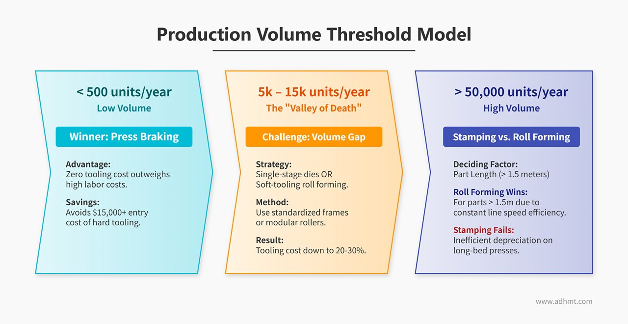
1. Production Volume Threshold Model
- < 500 units/year: The undisputed territory of Press Braking. In this range, tooling amortization is the key constraint. Although labor costs per part are relatively high, the “zero tooling cost” advantage of press braking easily outweighs the $15,000+ entry cost of hard tooling. The optimal strategy here is to accept higher marginal costs in exchange for avoiding heavy sunk costs.
- 5,000–15,000 units/year: The manufacturing “Valley of Death.” This is the most painful decision zone: press braking leads to skyrocketing labor and cycle times, while progressive stamping dies require volumes too low to justify tooling investment.
- Breakthrough strategy: Introduce single-stage dies or soft-tooling roll forming. By leveraging standardized die frames or modular roller sets, tooling investment can be reduced to 20–30% of the conventional cost—allowing safe passage through this awkward middle ground.
- > 50,000 units/year: The decisive stage of Stamping vs. Roll Forming. At this scale, press braking is no longer competitive. The deciding factor becomes part length: for parts longer than 1.5 meters, roll forming delivers a decisive efficiency edge. Stamping such parts requires long-bed presses with extremely high depreciation, while roll forming maintains constant line speed regardless of length.
2. The Hidden Cost of Scrap: The Silent Profit Killer
- The Achilles' heel of stamping: Skeleton scrap is a major cost sink often overlooked in financial reports. To ensure continuous feeding, stamping must retain carrier strips and connection bridges, typically achieving only 60–75% material yield. In other words, for every ton of steel purchased, about 300 kg ends up sold as low-value scrap.
- The roll forming advantage: Net-shape forming produces almost no waste beyond minimal start-up trims. Material utilization reaches 97–99.5%. During periods of high raw material prices—especially for copper, aluminum, or stainless steel—the savings from material efficiency alone can offset the entire equipment investment.
5.2 Technical Feasibility and Geometric Constraints Matrix
Using an incompatible process for a given design is the first step toward an ECO (Engineering Change Order) nightmare. A clear red-line matrix is essential to mitigate technical risks.
| Evaluation Dimension | Press Braking | Stamping | Roll Forming |
|---|---|---|---|
| Shape Flexibility | Linearly constrained. Can only handle straight bends; features like louvers, embosses, or blind holes require secondary operations. | The all-round champion. Supports drawing, flanging, embossing, and complex 3D freeforms with minimal geometric limitations. | Cross-section limited. Only constant profiles are possible; local protrusions or closed sections require inline punching integration. |
| Tolerance Capability | ±0.3 mm. Highly dependent on operator skill and sheet flatness; prone to cumulative errors. | ±0.1 mm. Progressive dies with in-die calibration deliver exceptional consistency (Cpk > 1.33). | ±0.2 mm (section); ±1.0 mm (length). Highly dependent on cut accuracy. |
| Material Thickness | Extremely versatile. Handles 0.5 mm to 25+ mm plates with ease; excels at thick-sheet bending. | Commonly 0.4–6 mm. Beyond 6 mm, press tonnage and cost rise exponentially. | Typically 0.3–8 mm. Excels in forming ultra-high-strength steels (1200 MPa+) with superior springback control. |
| ECO Cost | Very low. Usually requires only CNC reprogramming or segmented die changes, completed within minutes. | Very high. Die modifications affect the entire assembly and often involve heat-treated components, risking total die scrappage. | Extremely high. Adjusting even a corner radius may require re-machining 20+ rollers and complete re-tuning of the forming sequence. |
5.3 Production Agility and Supply Chain Considerations
In a VUCA world—volatile, uncertain, complex, and ambiguous—supply chain resilience often outweighs unit cost advantages.
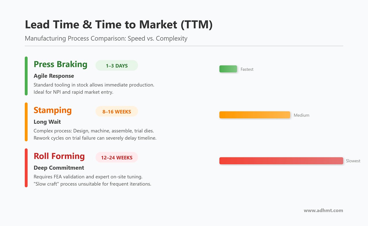
1. Lead Time and Time to Market (TTM)
- Press Braking = Agile Response (1–3 days): With standard tooling in stock, production can begin as soon as drawings are received. It’s the go-to choice during NPI (New Product Introduction) for rapid market entry.
- Stamping = Long Wait (8–16 weeks): Designing, machining, assembling, and trialing progressive dies is a complex system process. Any trial failure can severely delay project timelines due to rework cycles.
- Roll Forming = Deep Commitment (12–24 weeks): Roll design requires repeated FEA validation, and on-site tuning depends heavily on senior technicians’ expertise. It’s a “slow craft, fine result” process—unsuitable for projects with frequent design iterations.
2. Inventory Strategy and Cash Flow
Choosing stamping or roll forming inherently means accepting high MOQs (Minimum Order Quantities). To amortize costly setup and die-change operations, each run typically requires thousands of parts, tying up capital in inventory. In contrast, press braking naturally supports JIT (Just-In-Time) production, enabling single-piece flow and dramatically reducing inventory holding costs.
💡 Ultimate Decision Insight: Implement a dynamic lifecycle switching mechanism. During early R&D phases (EVT/DVT), enforce the use of press braking or laser cutting to validate designs—avoid premature tooling. As the product enters pilot production (PVT) with design freeze above 90%, transition to soft tooling. Only when annual demand exceeds 50k units and the projected lifecycle surpasses two years should the shift to progressive stamping or roll forming be executed.
Ⅵ. Engineering in Practice: DFM Design Guidelines and Quality Control
In the previous chapter, we tackled the strategic question of “how to choose.” This chapter dives into the tactical essence of execution—how to bring those choices to life on the shop floor. Once the design drawings reach production, the line between an excellent design and a disastrous one often comes down not to creativity, but to respect for the laws of physics. Instead of endlessly reworking molds during trials, it’s far more effective to mitigate risks early through Design for Manufacturing (DFM). In this section, we’ll approach the topic from the dual perspectives of the “firefighter” and the “quality enforcer,” presenting a practical DFM and quality-control guide complete with parameter formulas, defect maps, and insights into 2025’s intelligent quality systems.
6.1 Design for Manufacturing (DFM) — The Golden Rules
The truth of manufacturing is this: design isn’t just drawn—it’s calculated. Any drawing that defies physical principles will inevitably lead to high scrap rates and costly tool maintenance.
1. Press Braking: Geometry-Conscious Defensive Design
The core of DFM for press braking lies in managing interference and deformation.
- Minimum Flange Length: This is a common rookie mistake. During bending, the sheet must rest securely on both shoulders of the lower die’s V-opening.
- Rule of Thumb: Lmin ≈ 0.7 × V (where V is the lower-die opening, typically 6T–8T).
- Consequence: If the flange is shorter than this limit, the part can slip into the V-opening, making it impossible to form properly—potentially ejecting the part or damaging the tooling.
- Hole-to-Bend Distance: When a hole is placed too close to the bend line, tensile stress elongates it into an oval shape.
- Safe Zone: Dmin ≥ 2.5 × T + R (T = sheet thickness; R = inner radius).
- Practical Tip: If clearance is unavoidable, add a relief cut between the bend and the hole to interrupt stress transmission.
- Material and Minimum Radius: Never attempt to bend high-strength aluminum with R = 0.
- For mild steel, Rmin ≥ T is safe; for hard alloys like 7075-T6 or high-strength steels, use Rmin ≥ 3T–4T. Otherwise, micro-cracks will form on the outer surface, eventually causing fatigue failure.
2. Stamping: Balancing Tool Life and Material Flow
The essence of DFM for stamping is understanding the physical limits of shearing and material flow.
- Cutting Clearance: The soul of stamping quality.
- Guideline: For mild steel, set clearance at 8–10% of sheet thickness; for hard steel or stainless steel, 12–15%.
- Pitfalls: Too little clearance yields long burnished zones but sharp burrs and accelerated tool wear; too much clearance causes heavy rollover and tearing burrs.
- Deep Draw Radii: The punch’s bottom radius determines success or failure.
- If Rpunch < 3T, the punch acts like a dull knife, cutting through the blank before the draw completes. Ideally, use a generous radius and rely on a restrike operation to refine smaller radii later.
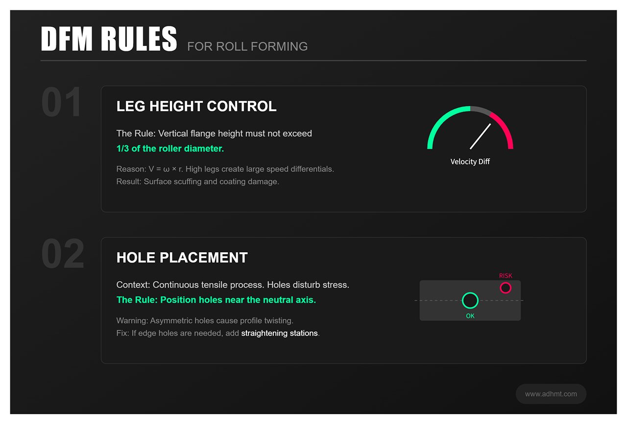
3. Roll Forming: Managing Line Speed in Continuous Forming
The DFM focus in roll forming is controlling longitudinal stress and speed differentials.
- Leg Height Limitation: The vertical flange height should not exceed one-third of the roller diameter.
- Principle: Because linear velocity (V = ω × r) differs between the roller root and tip, excessive leg height creates large speed differentials that cause surface scuffing and coating damage.
- Avoid Blind Holes and Asymmetric Features: Roll forming is a continuous tensile process. Pre-punched holes disturb local stress distribution and can twist the cross-section.
- Rule: Position holes near the neutral axis whenever possible. If edge holes are unavoidable, allocate additional straightening stations downstream.
6.2 Core Defect Diagnostics and Root Cause Analysis
When the production line halts and scrap piles up, engineers must trace the issue systematically—using “defect fingerprints” to pinpoint root causes quickly.
1. Springback Control: The Distinct Personalities of Three Processes
Springback manifests differently across forming methods:
- Press Braking: Appears as angle deviation.
- Countermeasure: This is a single elastic recovery. Adjust Y-axis depth using the press brake’s angle database or apply real-time compensation via LDS laser sensors.
- Roll Forming: Appears as bowing or twisting.
- Countermeasure: This results from cumulative stress release. Don’t just tweak the final straightening roll—check earlier stands for over-pressing that might cause uneven longitudinal stretch. To fix twist, adjust the Turk’s Head unit or enhance lubrication at the entry to prevent material drag.
- Stamping: Appears as sidewall curl.
- Countermeasure: This is caused by residual torque. Simply increasing press force won’t help; instead, use draw beads to raise feeding resistance or adopt reverse draw techniques to fully plastify the material at bottom dead center, eliminating elastic memory.
2. Defect “Fingerprint” Identification
- End Flare: Roll-forming-specific defect. After cutting, both ends of the profile open outward like petals.
- Root Cause: Excessive longitudinal fiber stretch.
- Solution: Modify the flower pattern by adopting the W-forming method—reverse-bend first, then form forward—to counteract the opening tendency through opposing stress.
- Wrinkling: Deep-drawing defect.
- Root Cause: Insufficient binder force in the flange area, causing uncontrolled material flow and tangential instability.
- Solution: Increase binder pressure or upgrade to nitrogen springs for a more consistent pressure curve.
- Die Marks: Press-braking defect.
- Root Cause: Direct metal friction at the V-die shoulders.
- Solution: Use a lower die with a larger radius or insert a urethane film for mark-free bending.
6.3 Quality Assurance System: From “Post-Mortem Inspection” to “Real-Time Diagnostics”
By 2025, quality control standards will no longer permit reliance on vernier calipers for after-the-fact inspections. True quality must be built directly into the manufacturing process.
1. In-Process Monitoring
- Stamping: Die Protection Sensors
- Piezoelectric or photoelectric sensors are embedded at critical positions within the die to monitor scrap ejection and strip alignment. If an anomaly such as double-sheet feeding is detected, the system can trigger an emergency stop within 0.01 seconds, preventing catastrophic damage to dies worth hundreds of thousands of dollars.
- Roll Forming: Laser Profiler
- Systems such as Profile360 generate real-time cross-sectional scans of profiles, much like a CT scan. When changes in radius or open-angle deviation are detected, the system issues an alert or automatically adjusts the roll gap through closed-loop control.
- Press Brake: LDS (Laser Detection System)
- During the ram’s downward stroke, lasers measure the actual bend angle after springback in real time, feeding the data back to the CNC system for automatic secondary compensation. This enables “first-piece pass” quality and eliminates trial bends and scrap.
2. Statistical Control Strategies: FAI vs. CPK
- Bending: Best suited for FAI (First Article Inspection).
- Bend accuracy depends heavily on both operator skill and machine condition. Once the first piece passes inspection, quality tends to remain stable as long as the operator remains attentive and the back gauge stays secure.
- Stamping/Roll Forming: Must strictly enforce CPK (Process Capability Index).
- In continuous high-speed production, 100% inspection is unrealistic. Instead, sampling control (e.g., 5 pieces per 1,000) should be implemented to plot a normal distribution of dimensional data.
- Cautionary Note: If a supplier claims, “We don’t need CPK; we do full manual inspection,” treat that as a red flag. In mass production, manual inspection can miss over 15% of defects. A CPK below 1.33 indicates an unstable process, meaning full inspection merely compensates for poor die design. Only a stable, capable process truly ensures lasting quality.

Ⅶ. Advanced Optimization: Hybrid Processes and Future Trends
Once each individual process has been pushed to its physical limits, further efficiency gains no longer come from faster rams or harder dies—but from breaking the “isolation” between processes. The factory of the future will not be a collection of isolated workstations, but an interconnected ecosystem of complementary technologies. This chapter explores how hybrid strategies and digital empowerment can create a manufacturing system with built-in resilience and adaptability.
7.1 Hybrid Manufacturing Strategies: Redefining the Boundaries of Cost and Efficiency
Traditionally, bending, stamping, and roll forming have been treated as mutually exclusive methods. Leading manufacturers, however, are blurring these boundaries—creating hybrid workflows that bridge the gap between cost and throughput.
- Stamping Blanks + Automatic Bending (Press Brake)
- Use Case: Complex, irregular enclosures with annual volumes of 10,000–30,000 units.
- Strategic Logic: Pure laser cutting is too slow for daily output requirements, while full progressive die investment (>$50,000) is excessive and risky amid frequent design changes.
- Solution: Develop a low-cost blanking die for instant forming of outlines and holes, followed by robotic bending using a sheet follower system for 3D shaping. This approach cuts tooling investment by 70% while retaining the flexibility to accommodate design revisions.
- Roll Forming + Inline Integration
- Use Case: Solar mounting brackets, warehouse uprights, automotive bumper beams.
- Strategic Logic: Eliminates hidden waste from semi-finished handling. Traditionally, roll forming is followed by offline punching or welding—adding inventory and positional errors.
- Solution: Build a fully integrated production line. Add a high-speed servo press for pre-punching before roll entry, and inline laser welding or flying cut-off at the exit. For instance, one robotic rail line achieved synchronized micron-level punching and closed-section welding at 120 meters per minute—compressing what used to require three separate workshops into one continuous process.
- Soft-to-Hard Tooling Transition
- NPI / Prototyping Stage (1–500 units): Fully digital manufacturing—laser cutting plus CNC bending—to validate designs with zero tooling cost.
- Ramp-Up Stage (500–5,000 units): Soft Tooling Stamping. Use modular die bases with simple inserts for critical holes or contours, while finishing other features via bending. This not only increases throughput but also enables early validation of stamping parameters.
- Mass Production Stage (>50,000 units): Full hard progressive dies are introduced once designs are frozen, minimizing capital risk at scale.
7.2 Intelligence and Industry 4.0 Evolution: From “Experience-Driven” to “Data-Driven”
If your factory still relies on veterans who “tune by ear,” you’re already a generation behind. The essence of Industry 4.0 is not just about making machines move—it’s about teaching them to think, predict, and adapt.
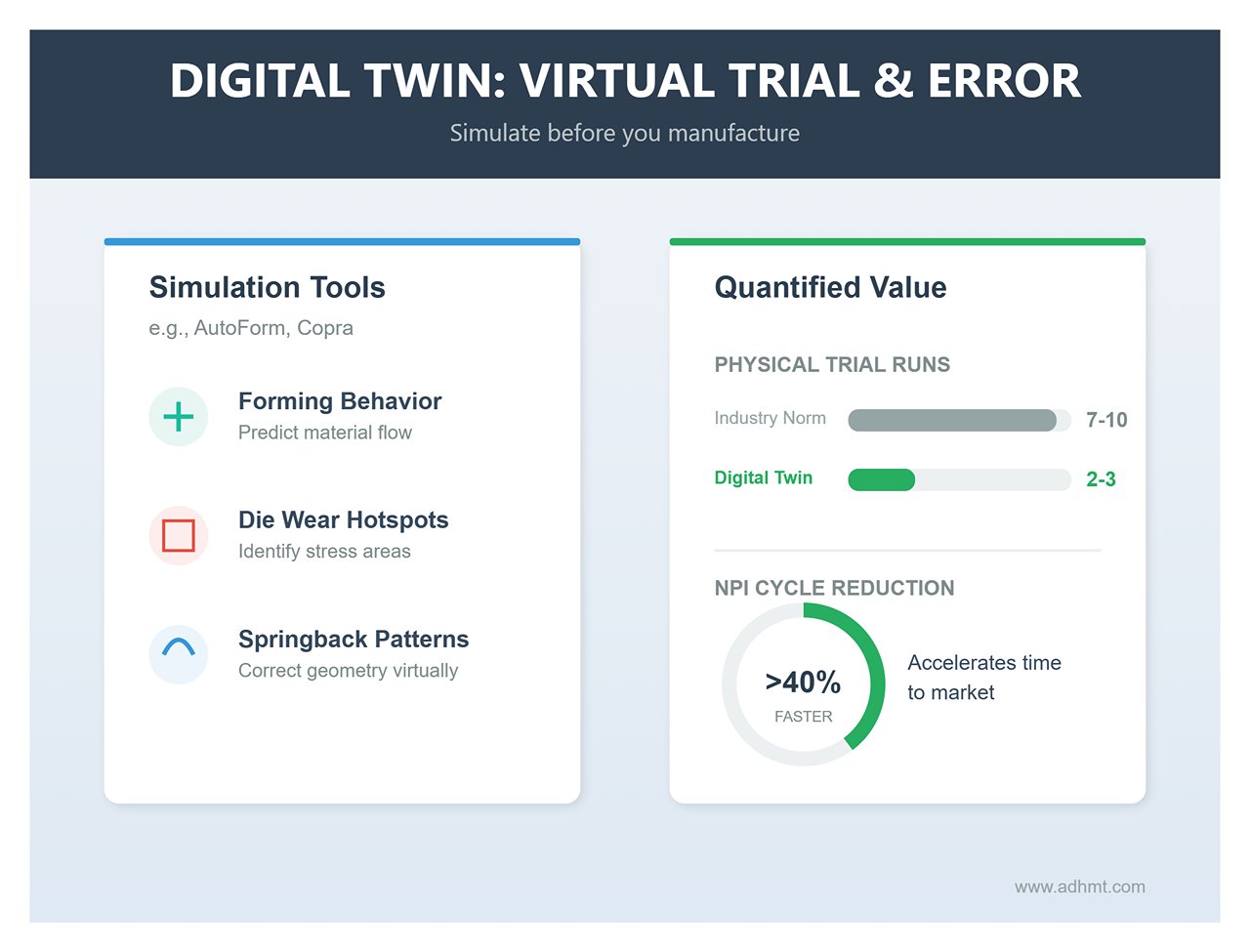
- Digital Twin: Virtual Trial and Error
- Before cutting the first sheet, advanced simulation tools like AutoForm or Copra can virtually process the “ten-thousandth part,” predicting not only forming behavior but also die wear hotspots and springback patterns.
- Quantified Value: Reduces physical trial runs from the industry norm of 7–10 down to 2–3, shortening the NPI cycle by more than 40%.
- Automation Integration and Collaborative Robots (Cobots)
- Automatic Tool Changer (ATC): The ultimate solution for high-mix, low-volume production. Premium press brakes (such as Amada or Trumpf) now come equipped with fully automated tool libraries capable of completing complex tool setups within two minutes. This completely eliminates non-productive time spent searching for, installing, and calibrating tools, boosting overall equipment effectiveness (OEE) from 40% to 80%.
- Human–Robot Collaboration: Collaborative robots no longer require safety cages. They handle heavy, repetitive sheet handling and follow bending operations, freeing operators to focus on quality inspection and process optimization.
- Closed-loop Adaptive Control
- Machines are no longer blind executors of commands. Modern roll forming lines use cross-section laser scanners to continuously monitor profile dimension deviations and automatically adjust roller gaps. Servo presses track tonnage curves to detect variations in material thickness, automatically fine-tuning bottom dead center positions—achieving true “in-motion quality control.”
7.3 Sustainable Manufacturing and Green Trends
Under the carbon neutrality agenda, green manufacturing has evolved from a corporate PR slogan into a tangible source of compliance cost management and competitive advantage.
- Energy Efficiency Revolution: The Triumph of Servo Technology
- Traditional hydraulic presses are notorious power guzzlers—the pump keeps running even when idle. Servo drive technology enables true “energy on demand,” consuming zero power when the slide is stationary. This reduces overall energy consumption by 40–60% while eliminating the environmental risks associated with hydraulic oil leakage and disposal.
- Material Circularity: Near Net Shape Manufacturing
- Scrap Equals Cost: In stamping processes, skeleton scrap is the primary source of material waste.
- Green Advantage: Roll forming, with its nearly 100% material utilization rate, is recognized as the most eco-friendly metal forming method. Combined with optimized nesting software and coil-based production, it not only reduces raw material procurement costs (BOM cost) but also serves as compelling evidence in ESG reports of a company’s progress toward lowering its carbon footprint.
Core Insight: Technological advancement isn’t about making processes more complicated—it’s about making decisions simpler. The future winners will be those who use hybrid manufacturing to balance cost, data intelligence to anticipate risk, and green manufacturing to secure long-term success.
Ⅷ. Future Trends
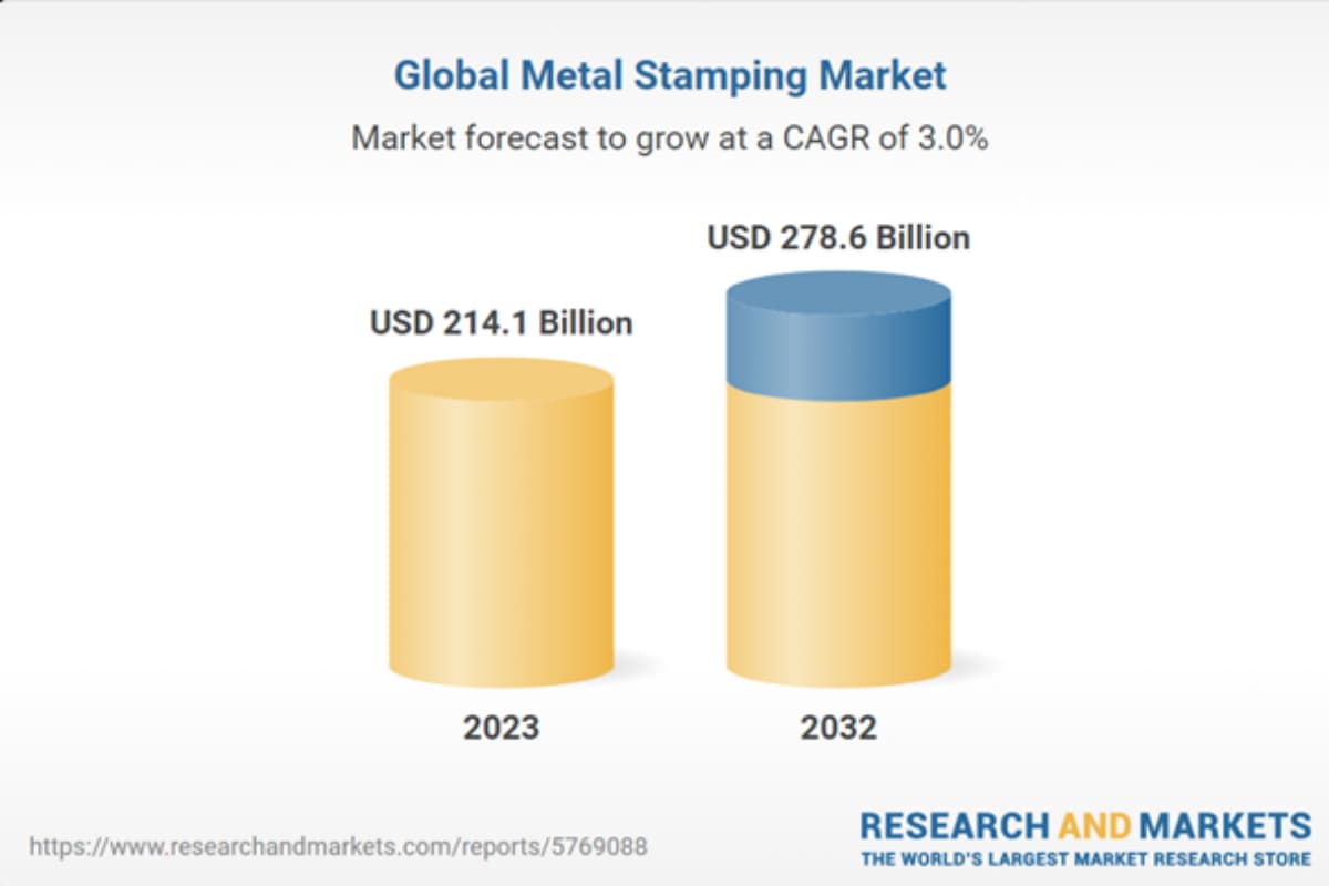
Expected to grow from USD 214.1 billion in 2023 to USD 278.6 billion in 2032, with a Compound Annual Growth Rate (CAGR) of 3.0%.
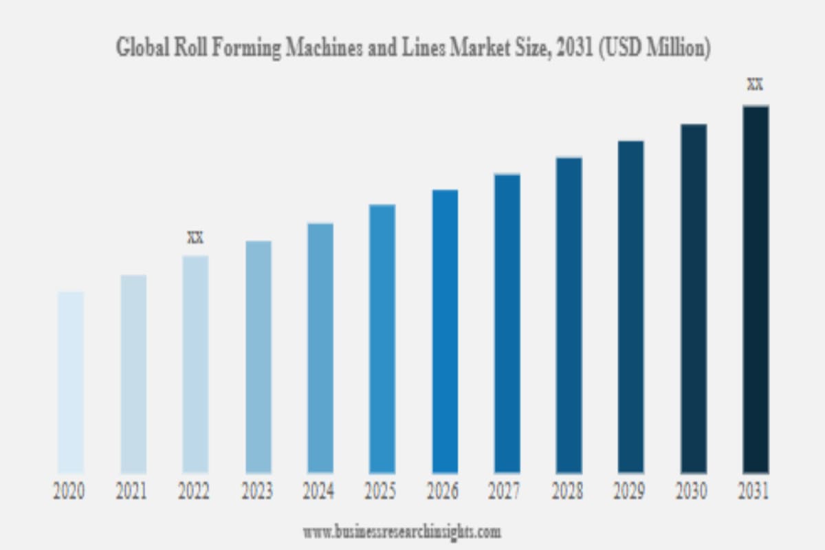
Projected to increase from approximately USD 8.5 billion in 2020 to over USD 11 billion by 2031, indicating a consistent upward trend.
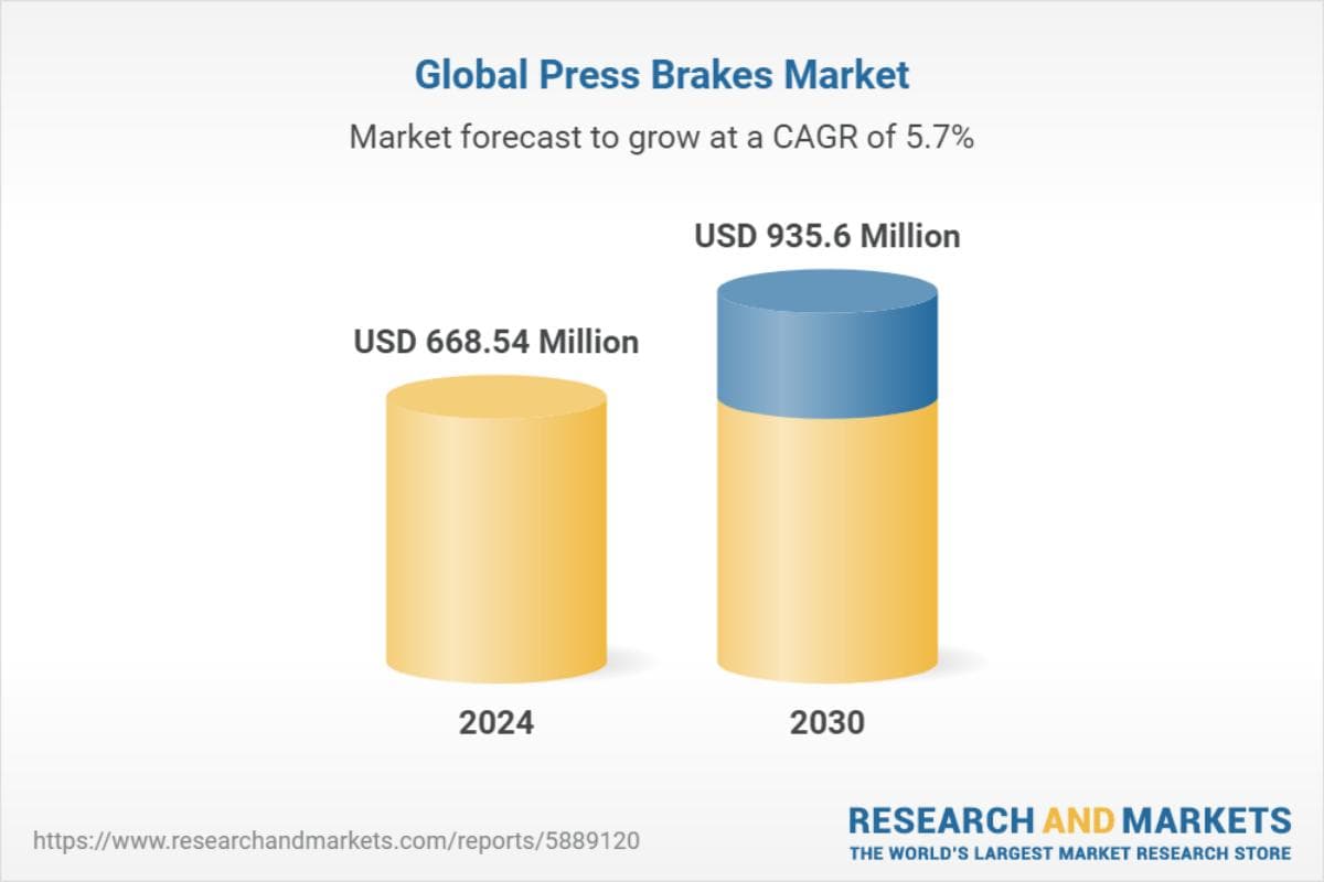
Forecasted to grow from USD 668.54 million in 2024 to USD 935.6 million in 2030, with a CAGR of 5.7%.
Based on the data, the following trends are anticipated for the future of press braking, stamping, and roll forming:
8.1 Continued Market Growth:
All three markets are expected to grow steadily, reflecting increasing demand for these technologies. The metal stamping market and press brakes market are projected to grow at CAGRs of 3.0% and 5.7%, respectively, while the roll forming machines and lines market also shows significant growth.
8.2 Advancements in Automation and Technology:
As the markets expand, manufacturers are likely to invest in advanced technologies to enhance efficiency, productivity, and precision. The adoption of automation and smart manufacturing technologies will be key drivers of future growth.
8.3 Expansion into New Industries and Applications:
With rising demand, these technologies are expected to penetrate more industries and applications. Sectors such as automotive, aerospace, construction, and electronics will drive further development and adoption of high-precision and efficient production technologies.
8.4 Increased Demand for Customization:
As customer demand for customized products grows, manufacturers will need flexible production technologies to meet diverse requirements. This will spur further innovation and development in roll forming, stamping, and press braking technologies.
Ⅸ. Conclusion
Press braking, stamping, and roll forming are all effective metal processing processes in the sheet metal industry, each with its own set of distinct advantages and disadvantages. Stamping machines, roll forming machines, and press brakes are commonly used in the sheet metal industry.
ADH is a professional manufacturer of press brakes, laser cutting machines, and shearing machines, with years of experience in the industry. Our range of press brakes includes CNC Press Brake, NC press brakes, and Tandem Press Brake brakes. For detailed information about our press brake products, please visit our website or contact us for customized solutions. You can also browse our brochures to learn more about our full product line.


