In the evolving landscape of industrial fabrication, press brake vs. solid processing represents more than a choice between two forming methods—it embodies a fundamental tension between deformation and removal, between shaping and sculpting.
This decision not only influences mechanical performance and cost efficiency but also determines the overall lifecycle value of a product. From microstructural behavior to design-for-manufacturing (DFM) strategy, understanding this dichotomy is essential for engineers seeking optimized precision, sustainability, and competitiveness. The following sections decode the physics, economics, and design logic behind this crucial manufacturing decision.
I. Cognitive Reconstruction: Unveiling the Fundamental Contest Between “Deformation” and “Removal”
The essence of manufacturing is not merely transforming an object’s external geometry, but reorganizing its microstructure and redistributing energy. When you hesitate between Press Brake forming and Solid machining, you’re essentially making a strategic decision about the fate of atoms. This goes far beyond process selection—it’s a philosophical duel between two physical doctrines: conservation and sacrifice.
1.1 Defining the Core Conflict: Plastic Flow vs. Geometric Carving
To grasp the true difference between the two, we must zoom in to the microscopic world of metallic lattices.
Press Brake forming embodies the art of plastic flow—a manufacturing logic rooted in mass conservation. Under the microscope, bending is an orchestrated migration of atoms. By applying pressure beyond the yield point but below the ultimate strength, we harness the dislocation mechanism to guide the crystal lattice to slip and rearrange while maintaining material continuity.
It’s akin to training the material to follow the mold’s direction into a new shape. The core principle is “nothing wasted”—every gram you purchase becomes part of the final product.
Solid Processing, by contrast, represents the violence of geometric carving—a manufacturing logic based on material subtraction. Whether through CNC milling or turning, the essence lies in severing atomic bonds with the tool’s shear force, creating localized fracture.
It’s like Michelangelo sculpting David—relentlessly stripping away the “unnecessary” to reveal form and truth. The cost is substantial material waste and the destruction of the material’s original integrity.
The essence of the conflict: Bending leverages a material’s ductility—its ability to yield without breaking—while solid machining relies on its brittleness—its capacity to fracture cleanly into chips. The former works with the material; the latter conquers it by force.
1.2 Why This Decision Determines a Product’s Fate
This is not an exaggeration. The chosen process directly dictates a part’s physical behavior under extreme conditions—and can even determine the economic viability of an entire project.
- Survival of the Microstructural “Bloodline” (Grain Flow): Often overlooked by engineers, this is the silent killer of component reliability. During rolling or forging, metals develop fiber flow, a grain orientation pattern similar to wood grain.
- The Bending Advantage: Press Brake forming follows these flow lines, much like bending a branch—its fibers deform but remain continuous. This continuity gives bent parts superior fatigue and impact resistance.
- The Machining Cost: When a part (say, an L-shaped bracket) is milled from a solid block, the tool mercilessly severs these flow lines. Each cut grain end becomes a potential stress riser, a fertile ground for fatigue cracks. In aerospace or heavy-duty applications, this can mean fatigue life differences by several orders of magnitude.
- Economic Reality – The “Buy-to-Fly Ratio”: For costly materials like titanium or Inconel, solid machining can be a profitability nightmare. Machining thin-walled parts from solid billet often means a material removal rate (MRR) exceeding 90%. In other words, for every $100 of material purchased, $90 ends up as scrap—waste that may even cost money to dispose of. Press Brake forming, by contrast, is near-net-shape, with material utilization approaching 100%. In an era of soaring raw material prices, this often defines whether a bid is competitive or doomed.
1.3 The “Boundary Line” of Applicability
Although hybrid manufacturing is increasingly blurring the boundaries, in practical engineering decisions, there remain distinct physical and economic thresholds separating Press Brake forming and Solid machining.
| Dimension | Press Brake (Sheet Forming) | Solid Processing (Machining) | Decision Threshold (The Tipping Point) |
|---|---|---|---|
| Structural Characteristics | Constant thickness; ideal for sheet structures formed by folding 2D layouts into 3D shapes. | Highly flexible; enables variable wall thickness, internal cavities, freeform surfaces, and undercuts. | Wall thickness variation: if the design requires uneven walls for stress optimization, solid machining or casting is mandatory. |
| Precision Grade | IT10 – IT14; affected by springback and sheet thickness tolerance—micron-level accuracy is difficult. | IT5 – IT8; tool paths are precisely controlled—essential for high-precision mating surfaces. | Fit tolerance: if bearing bores or precision sliding fits are required, machining is necessary (or as a secondary step after bending). |
| Strength-to-Weight Ratio | High; stiffness achieved via geometric inertia (e.g., ribs), resulting in extremely light structures. | Moderate/Low; solid parts are heavier, and achieving extreme lightness demands extensive cutting at exponential cost. | Weight reduction: due to structural efficiency, bent parts dominate in automotive chassis and aerospace sheet-metal applications. |
| Response Speed | Fast; quick die changes, simple programming—ideal for small batches and diverse product mixes. | Slow; complex parts require custom fixtures and intricate toolpath planning, extending cycle times. | Lead time: for urgent orders or prototype validation, bending can deliver 3–5 times faster than machining. |
In summary: Don’t try to form an engine block with a press brake, and don’t attempt to mill a car body panel on a CNC. Reconstructing one’s understanding begins with respecting this boundary line. Next, we’ll dive into the underlying physics to see how these variables can be precisely controlled.
II. Mechanistic Principles: A Deep Dive into Material Physics
If Chapter 1 examined process selection from a macro perspective, this chapter cranks up the magnification to the atomic scale. Whether it’s the downward stroke of a press brake or press break or the cutting action of an end mill, both are processes of energy transmission and transformation within the material. Understanding this physical interplay is the foundation for mastering dimensional accuracy and cost efficiency.
2.1 Microstructural and Mechanical Performance Contrast
At the microscopic level, Press Brake forming and Solid machining influence material properties in profoundly different ways—differences that directly shape fatigue life and load-bearing capacity.
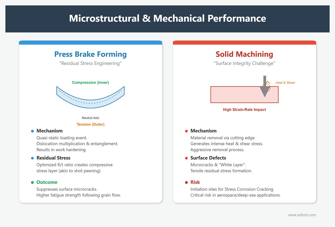
- The “Residual Stress Engineering” of Bending: The bending process is a quasi-static loading event. Under external force, the outer layer of the sheet is stretched, the inner layer compressed, and in between lies a neutral axis where stress equals zero. This induces dislocation multiplication and entanglement within the material, leading to pronounced work hardening. More critically, bending introduces a complex residual stress field in the formed region. While uncontrolled residual stress may cause springback, proper process design—such as optimizing the bend radius-to-thickness ratio (R/t)—can create a compressive stress layer akin to shot peening, effectively suppressing the initiation of surface microcracks. For parts subjected to cyclic loads, bent components that follow the grain flow often exhibit higher fatigue strength than machined ones. For more on optimizing bending parameters, explore the press braking process in detail.
- The “Surface Integrity Challenge” of Solid Machining: In contrast, solid machining—especially high-speed milling—is a high strain-rate impact process. As the cutting edge removes material, it generates intense heat and shear stress at the surface. Although the resulting geometry may be highly precise, the surface microstructure often contains microcracks, a so-called “white layer,” or tensile residual stress. Without subsequent heat treatment or surface strengthening, these micro-defects left by the “aggressive removal” process can easily become initiation sites for stress corrosion cracking (SCC). In extreme environments such as aerospace or deep-sea applications, this can be catastrophic.
2.2 The Underlying Logic of Precision Control
Why is it difficult for a press brake to achieve the micrometer-level accuracy of a CNC machining center? The answer lies not in equipment sophistication but in the fundamentally different physical behaviors each process must contend with.
- Bending: A Battle with Elastic Memory The core challenge of bending accuracy lies in springback and machine deflection. Once the bending force is released, the metal tends to recover its elastic deformation, causing angular deviation. This is a dynamic variable affected by material batch variations, thickness fluctuations, yield strength differences, and even local rolling-induced hardening within the same sheet. The high cost of modern press brakes stems from their integration of real-time angle measurement and dynamic crowning compensation—systems that allow the machine to sense the material’s resistance and continuously adjust ram depth and compensation. It is, in essence, a real-time negotiation between machine and material.
- Solid Machining: The Enforcement of a Rigid Path The precision logic of solid machining operates under a “rule of rigidity.” The machine tool, with its high stiffness and spindle speed, forces the cutting tool to follow its programmed coordinates. Provided the workpiece is firmly clamped and the tool is not excessively worn, elastic deformation within the system remains minimal. Thus, solid machining works by eliminating variables, using rigidity to suppress material behavior; bending, on the other hand, requires managing variables, coordinating with the material’s physical response. This explains why bending tolerances are typically ±0.2 mm, while machined parts routinely achieve ±0.01 mm.
2.3 Material Utilization and Energy Efficiency
Amid carbon neutrality goals and volatile raw material prices, physical mechanisms ultimately translate into tangible financial outcomes.
- The “Zero-Waste” Philosophy of Near-Net Shaping The press brake process belongs to the near-net-shape category. Apart from minimal trimming scrap, nearly every gram of input material becomes part of the final product—a near-perfect embodiment of mass conservation. In contrast, solid machining, particularly for complex geometries, often suffers from a staggering Buy-to-Fly Ratio (BTF). Machining a 5 kg aerospace bracket from a 50 kg aluminum billet means 90% of the high-value material is reduced to low-value chips. This is not just a material waste but also a massive loss of the energy invested in smelting and transportation. For companies evaluating sustainable manufacturing, downloading technical brochures can provide valuable insights into energy-efficient forming systems.
- Differences in Energy Density From a work-energy perspective, bending requires only enough energy to overcome the material’s yield strength and induce plastic deformation—resulting in a relatively low energy density. Modern servo-electric press brakes consume power only during ram movement, with extremely low standby energy use. Machining, however, must overcome high shear forces to break metallic bonds and simultaneously power cooling, chip removal, and high-speed spindles. For equivalent volumes of material formed or removed, machining typically consumes 5–10 times more energy than bending.
Chapter Summary: Choosing between Press Brake and Solid Processing is essentially a choice between harnessing material plasticity and fighting atomic bonding energy. The former works with the material’s natural flow—efficient yet harder to control precisely; the latter imposes precision through destruction—accurate but costly and wasteful. In the next chapter, we will quantify these physical principles and build an actionable decision matrix. If you need professional guidance in selecting the right forming or machining solution, feel free to contact us.
III. Practical Application: The Six-Dimensional Decision Matrix and Quantitative Evaluation
Having understood the micro-level physical differences, we now shift our focus back to the engineering floor. In project management and process selection, intuition can be expensive—data, on the other hand, does not lie.
To help you make rational trade-offs between Press Brake (bending) and Solid Processing (machining), we’ve developed a Six-Dimensional Decision Matrix. This is not just a checklist but a defense system against profit erosion.
3.1 Geometric Topology Analysis (Topology Check)
This is the first “gateway” in process selection. The geometric laws of the physical world are immutable; if a design fails at the topological level, subsequent cost analyses become meaningless.
- The Hard Constraint of the Gaussian Curvature Law (K = 0) The mathematical essence of bending is the manipulation of developable surfaces. This requires that the surface’s Gaussian curvature K be zero everywhere. In simpler terms, any shape that cannot be flattened into a plane without tearing or wrinkling—such as spheres, hyperbolic surfaces, or deep-drawn cavities—lies beyond the capability of a press brake.
- Decision Red Line: If a design includes non-developable 3D features or undercuts that cannot be addressed by relief slots, Solid Processing or casting becomes the only viable option.
- The Economic Equation of the Solid Envelopment Ratio (α) For solid machining, we calculate the Solid-to-Envelope Ratio (α)—the ratio of the final part volume to the smallest enclosing raw material volume.
- Evaluation Criterion: If α < 0.3, it means over 70% of the material will be machined away as waste. This “carving a toothpick from a marble block” approach is economically unsustainable. In such cases, it is essential to evaluate whether the design can be re-engineered into a shell structure through sheet metal bending and welding or riveting.
3.2 Cost Structure Decomposition (TCO Analysis)
Many companies, when calculating costs, focus solely on machining labor hours while overlooking the biggest hidden factor in TCO (Total Cost of Ownership)—material utilization efficiency.
- The Harsh Reality of the Buy-to-Fly Ratio (BTF): This gold-standard metric in aerospace manufacturing is equally relevant in precision engineering.
- Solid Processing: For complex structural parts, the BTF often reaches 10:1 or even 30:1. In other words, out of 10 kilograms of aerospace-grade aluminum or titanium purchased, only 1 kilogram becomes part of the final product—while the remaining 9 kilograms turn into chip waste that must be disposed of at a cost.
- Press Brake: As a near-net-shape forming process, its BTF typically remains around 1.1:1, with most losses coming from material nesting and trimming.
- Cost Threshold: When raw materials account for more than 50% of a part’s total cost, the cost advantage of Press Brake forming expands exponentially.
- Hidden Post-Processing Costs: Machined surfaces usually show noticeable tool marks (Ra ≈ 3.2 μm). To achieve a cosmetic finish, additional polishing or sandblasting is required. In contrast, high-quality cold-rolled sheet metal naturally offers a smooth Ra < 0.8 μm surface—bend-formed parts typically need only edge finishing before painting. In mass production, this can reduce surface treatment expenses by 15%–20%.
3.3 Volume–Cost Curve

In the cost–production volume coordinate system, there exists a well-known “Valley of Death”—the range where decision-making errors are most likely to occur.
- Zone I: Prototypes and Very Small Batches (1–50 units)
- Winner: Solid Processing
- Logic: CNC machining can start immediately without tooling. Modern CAM software makes true one-off production feasible. Choosing bending at this stage is uneconomical, as die setup and first-piece trial costs, when spread over just a few units, become disproportionately high.
- Zone II: Valley of Death / Decision Dilemma (50–500 units)
- Status: Stalemate
- Strategy: This is where engineering judgment matters most. If the part can be formed using standard tooling (such as a V-die), bending wins; if special forming tools are required, CNC machining may still be more cost-effective.
- Breakthrough Approach: Within this range, consider laser cutting + simple bending, or use 3D-printed soft tooling to lower the entry barrier for bending operations. For practical case studies and technical references, check ADH Machine Tool.
- Zone III: Mass Production (>1000 units)
- Winner: Press Brake
- Logic: CNC machining time scales linearly (10 minutes per part means 10,000 minutes for 1,000 parts). Bending, by contrast, is instantaneous, and efficient sheet nesting drastically cuts material waste. As volume grows, the two cost curves diverge sharply—the marginal cost of bending approaches the raw material cost itself.
3.4 Precision and Functional Fit
If your drawing specifies ±0.01 mm, forget about using a press brake. But the real question is: does your product truly require that level of precision?
- Absolute Accuracy vs. Functional Tolerance
- Solid Processing: This is the “hard power” approach—machine rigidity easily achieves ±0.005 mm to ±0.02 mm, ideal for bearing fits or airtight sealing surfaces.
- Press Brake: Limited by material springback and sheet-thickness tolerance, achievable accuracy typically ranges ±0.2 mm to ±0.5 mm.
- Engineering Wisdom: A skilled engineer doesn’t force a press brake to match CNC precision but instead designs adaptively. For instance, use slotted holes instead of round ones, or self-locating clips to absorb ±0.5 mm fabrication variance through geometric tolerance management.
- Structural Efficiency: The Dialectic of Stiffness: Solid parts achieve stiffness by adding thickness—a “brute-force” method. Sheet-metal parts, however, gain stiffness through geometric inertia.
- Practical Advice: Don’t try to replace solid blocks with thick sheet bends. Instead, design ribs, flanges, or box structures so that thin sheets achieve multiple times the bending stiffness of equivalent solid plates at the same weight. This isn’t just a process choice—it’s a triumph of lightweight design.
IV. Advanced Optimization: Hybrid Manufacturing and DFM Strategies
Beyond the binary choice of black or white lies the true art of engineering—mastering the shades of gray. When we combine the material efficiency of Press Brake forming with the geometric precision of Solid Processing—or cleverly transition between them through design—we surpass the physical limits of any single process. This chapter explores how hybrid workflows and design for manufacturability (DFM) can reshape cost structures.
4.1 The “Solid–Bending” Hybrid Workflow
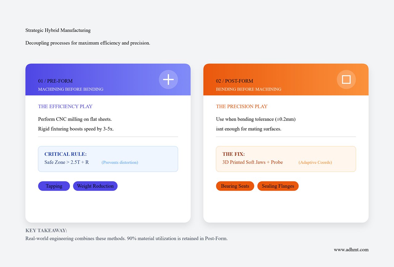
In real-world engineering, the optimal solution is rarely “A or B,” but rather a strategic combination of A and B. The essence of hybrid manufacturing lies in process decoupling—using machining for high-precision interfaces and bending for overall structure and material efficiency.
- Strategy 1: Pre-Form Machining: This is the go-to method for handling complex hole patterns or localized thinning features. Perform CNC milling or drilling while the sheet is still flat, then bend it into shape.
- Advantages: Fixturing flat sheets is far simpler and more rigid, boosting machining efficiency by 3–5× compared with irregular shapes. It also enables easy countersinking, tapping, or pocket milling for weight reduction or clearance.
- Technical Notes: Accurately calculate the flat pattern and K-factor. Always reserve a “safe deformation zone”—keep any precision features at least 2.5× the sheet thickness + bend radius away from the bend line to prevent hole distortion or thread damage during forming.
- Strategy 2: Post-Form Machining: Use this approach when bending accuracy (typically ±0.2 mm) cannot meet the tolerance requirements of mating surfaces such as bearing seats or sealing flanges.
- Advantages: Retains over 90% of the material utilization efficiency of bent components, requiring only minimal machining at critical areas.
- Challenges & Solutions: Fixturing irregularly shaped bent parts is the biggest hurdle. Modern approaches favor the use of flexible hydraulic clamps or 3D-printed negative-shape soft jaws to hold the workpiece securely. A machine probe is then used to establish an adaptive coordinate system, compensating for geometric deviations introduced during bending.
4.2 DFM (Design for Manufacturing) Transformation Techniques
Shifting from a solid-model mindset to a sheet-metal mindset is essentially a dimensional simplification—converting the volumetric fill of a 3D solid into the spatial folding of a 2D sheet. Mastering the following DFM transformation techniques can typically yield a 40%–70% cost reduction.
- Stiffness Substitution Principle: Using Geometry Instead of Mass In solid machining, engineers often increase wall thickness to improve stiffness. In sheet-metal design, one must instead exploit the moment of inertia of the cross-section.
- Conversion Technique: Do not use a 10 mm thick flat plate to resist bending moments; use a 3 mm sheet bent into a 20 mm-high stiffening rib or box section instead. By increasing the section height (h), stiffness grows cubically (h³). This approach saves around 70% of material while dramatically reducing weight.
- Reconstructing the Joining Logic: Self-Fixturing Design Solid parts are typically monolithic, whereas sheet-metal structures often require welding or riveting. To avoid costly welding fixtures, adopt tab-and-slot self-locating designs.
- Practical Guide: Include small tabs and matching slots in the flat pattern of the part. After bending, the components interlock like LEGO pieces for self-alignment. This eliminates the need for welding jigs and keeps assembly tolerances within laser-cut accuracy (±0.05 mm).
- Avoiding Process Dead Zones: Relief Cuts and Minimum Flange Lengths
- Corner Relief: While internal corners in solid parts can be sharp, bent parts must have fillets (matching the die tip radius). Where multiple faces converge, relief cuts must be provided to prevent material tearing.
- Minimum Flange Rule: The flange length must exceed half of the V-die opening width (typically 3–4 times the sheet thickness). Otherwise, the sheet will slip into the die opening instead of bending, resulting in process failure.
4.3 Intelligent Manufacturing Enablement
Traditional bending operations have long relied on the operator’s experience to correct springback and machine deflection—an inherent disadvantage compared with standardized CNC machining. However, Industry 4.0 technologies are rapidly closing this gap.
- Closed-Loop Angle Control Systems (LUV / ACB) High-end press brakes no longer operate blindly. Equipped with laser-based angle measurement or contact sensors, they monitor changes in bending angles in real time during the forming process.
- Practical Value: The system automatically detects the springback characteristics of the material (even when yield strength varies within the same batch) and adjusts the ram depth within milliseconds. This ensures the first piece meets specifications, eliminating the costly “test–adjust–retest” setup cycle.
- Dynamic Crowning Compensation To correct the tendency for the middle of long parts to bend less accurately due to machine deflection, modern equipment employs CNC-controlled hydraulic crowning tables. Based on bending force, sheet thickness, and part length, the system generates a microscopic counter-deflection at the table center, maintaining consistent angles within ±0.3° across the entire length.
- Offline Programming and Digital Twin Process planning is now moving from the shop floor to the office. Using software such as BySoft or TruTops, engineers can simulate the entire bending sequence in a virtual environment, automatically generating operations, detecting collisions, and optimizing backgauge paths. This transforms the press brake from a “craft-dependent machine” into a “standardized execution unit,” enabling even entry-level operators to produce perfect parts.
V. Practical Applications: Case Studies and Lessons Learned
Physics never negotiates, and cost reports never lie. Theoretical advantages must prove their worth under real production conditions. The following two cases illustrate contrasting engineering strategies: one achieves maximum cost reduction, while the other preserves performance integrity through necessary investment. We also summarize the five most common DFM “fatal flaws” observed on the shop floor—hard-earned lessons paid for in scrap.
5.1 Case A: Heavy Equipment Load Bracket (Cost Down 60%)

Background: The hydraulic pump mount for a certain excavator model was originally designed using traditional heavy-industry methods—a welded H-shaped structure made from 20 mm Q345B plate, with an annual production volume of 5,000 units.
- Pain Points: Excessive heat input during welding caused severe distortion, requiring a 3 mm machining allowance for surface leveling. In addition, all weld seams required ultrasonic testing (UT), leading to long cycle times and high scrap rates.
Redesign Strategy: “Bend Instead of Weld” + “High-Strength Steel Thinning” Engineers challenged the assumption that load-bearing structures must use thick plates and implemented the following changes:
- Material Upgrade: Replaced Q345 steel (yield strength 345 MPa) with Strenx 700 high-strength steel (yield strength 700 MPa).
- Topology Redesign: Transformed the original welded H-section (base plate + two vertical plates) into a single-piece U-shaped bent structure.
- Process Decoupling: Added stress-relief slots and self-locating tabs via laser cutting; after bending, only minimal intermittent corner welding was required, eliminating the need for full-penetration welds.
Performance Comparison:
| Metric | Original Process (Welding + Milling) | New Process (High-Strength Bending) | Key Improvement |
|---|---|---|---|
| Material Spec | Q345B (t=20mm) | Strenx 700 (t=8mm) | 60% weight reduction (optimized inertia) |
| Process Chain | Cutting → Beveling → Assembly → Welding → Stress Relief → Milling | Cutting → Bending → (Minor Welding) | 75% cycle time reduction |
| Unit TCO | 125 | 48 | 61% total cost reduction |
Core Insight: The press brake is more than just a forming tool—it’s the most effective means of eliminating welding from the process chain. Although high‑strength steel carries a higher unit cost, the ability to reduce thickness (leveraging the t² stiffness effect) and eliminate secondary steps such as beveling, inspection, and milling drives a dramatic drop in total cost of ownership (TCO). In heavy‑duty structures, the principle of “high‑strength thin plate + large‑radius bending” is fast becoming the golden rule that replaces traditional thick‑plate welding assemblies.
5.2 Case B: Avionics Heat Sink Base (Precision Win)
Background: The heat sink base for a military‑grade UAV radar was required to mount high‑power IGBT modules. With extremely high heat flux density, the technical specification demanded a mounting surface flatness better than 0.02 mm per 100 mm.
Trial and Failure: In the pursuit of extreme lightweight design and lower machining costs, the team initially attempted to form the base by bending AL6061‑T6 aluminum sheet, hoping to compensate for surface gaps using thermal interface material (TIM).
Failure Scene: Inevitably, material springback caused the bent part to warp into a subtle “saddle” shape (measured flatness ≈ 0.15 mm). When screws were tightened, the brittle ceramic substrate of the IGBT fractured under stress from the deformed base. Surviving modules suffered excessive thermal resistance and went into thermal runaway during full‑power testing.
Final Solution: The “Solid‑Fin” hybrid manufacturing strategy
1. Base: Reverted decisively to solid CNC machining. The base was milled from a solid aluminum block, achieving flatness of 0.01 mm and surface roughness of Ra 0.8, ensuring atomic‑level contact with the IGBT modules.
2. Fins: Slots were milled on both sides of the base to insert folded aluminum fins, which were then brazed in place.
Results Analysis: Although the CNC‑machined base cost five times more than the all‑bent version, it preserved the critical thermal resistance (Rth) and reliability margins. This case vividly demonstrates a hard truth: for thermal interfaces, bearing housings, and precision optical mating surfaces, never gamble on sheet metal. The high cost of CNC machining buys you the priceless certainty of physical dimensions.
5.3 Pitfall Guide: The 5 Mistakes Engineers Most Often Make
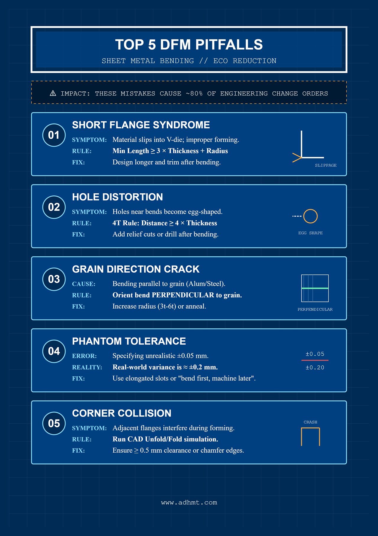
In DFM (Design for Manufacturing) reviews, these five seemingly minor mistakes account for roughly 80% of all Engineering Change Orders (ECOs). Avoid them, and your design will move from “looks feasible” to “manufacturable.”
1. The “Short Flange Syndrome”
- Symptom: The designed flange length L is too short, causing the sheet to slip into the V‑die opening during bending, preventing proper forming and often resulting in slippage or surface damage.
- Rule: Follow L_min ≈ 2.5 × V (where the V‑die width is typically six times the sheet thickness). Easy rule of thumb: minimum flange length ≥ 3× sheet thickness + bend radius. If a short flange is unavoidable, design it longer and trim it after bending (secondary machining).
2. “Hole Distortion”
- Symptom: A round hole placed too close to the bend line becomes elongated or “egg‑shaped” due to plastic flow during bending, preventing fastener insertion.
- Rule: Apply the 4T rule. The distance d from the hole edge to the bend line should be ≥ 4 × t (sheet thickness). If space is limited, add a relief cut along the bend line to break stress transfer, or drill the hole after bending.
3. “Grain Direction Crack”
- Symptom: Aluminum alloys (e.g., 6061‑T6, 7075) or high‑strength steels develop severe orange‑peel cracks or even fracture along the outer bend surface.
- Cause: The bend line runs parallel to the rolling grain direction, effectively splitting the material like wood along its grain.
- Rule: Whenever possible, orient the bend line perpendicular to the grain direction. If layout constraints prevent this, increase the bend radius R to 3t–6t, or perform annealing before bending.
4. “Phantom Tolerance”
- Symptom: Drawings specify a hole‑to‑hole tolerance of
±0.05 mmon bent parts. - Reality: Although the press brake’s ram repeatability may reach ±0.01 mm, variations in material thickness, springback, and tool wear typically push real‑world part tolerances to
±0.2 mmor more. - Rule: Apply general bending tolerances according to ISO 2768‑m or ‑c classes. For precision holes, use elongated slots to absorb variation, or adopt a “bend first, machine later” approach.
5. “Corner Collision”
- Symptom: Two adjacent 90° flanges designed in the flat pattern interfere with each other during forming, preventing full closure.
- Rule: Don’t rely on mental geometry. Always run a bend simulation (Unfold/Fold) in CAD software such as SolidWorks or CATIA. Leave at least 0.5 mm clearance between adjacent flanges or design a chamfered edge to prevent interference.
VI. Synthesis: Building an Enterprise‑Level Process Knowledge Base
After exploring atomic‑scale plastic deformation, shop‑floor cost trade‑offs, and design‑side topology optimization, the debate of "Press Brake vs. Solid" is no longer a simple binary choice. It embodies two core philosophies of manufacturing strategy: the pursuit of geometric certainty versus the pursuit of material and process efficiency. To transform these dispersed insights into organizational decision assets, we must build a standardized process‑selection knowledge base.
6.1 Decision Roadmap

In engineering practice, intuition is often not only costly but dangerous. We recommend institutionalizing the following Four‑Stage Filter Method as a standard DFM review procedure—a logical algorithm for determining the optimal manufacturing route early in the project lifecycle.
Step 1: The Geometry Sieve
- Key Question: Does the part exhibit zero Gaussian curvature throughout? Are there any undercuts or variable wall thicknesses that cannot be resolved through bending?
- Criterion: If the answer is “no,” or if non-developable 3D features exist, the part must proceed to Solid Processing (such as casting or 3D printing). This is a hard constraint imposed by physical laws—there is no workaround.
Step 2: The Precision Sieve
- Key Question: Do functional mating surfaces require tolerances tighter than ±0.1 mm? Is a surface roughness below Ra 1.6 μm specified? Does the design involve high-pressure sealing surfaces?
- Criterion: If any of these conditions apply, Solid Processing should be the first choice, or consider a hybrid route combining Press Brake forming with secondary machining. Never push a bending machine to the limits of design precision—it’s a losing battle.
Step 3: The Material Economics Sieve
- Key Question: Is the solid-to-envelope ratio below 0.4? Is the raw material cost above $20/kg (e.g., titanium or superalloys)?
- Criterion: If both conditions are met, Press Brake or welded sheet-metal fabrication is strongly recommended. In such cases, the material waste of Solid Processing can quickly erode profit margins—unless the product commands an exceptionally high selling price.
Step 4: The Volume Sieve
- Key Question: Is the annual production volume greater than 500 units? Is product demand stable over time?
- Criterion: If production exceeds the threshold, Press Brake takes the lead—the tooling cost is amortized over volume, and material efficiency gains are magnified. For prototype runs or highly customized small batches under 50 units, the mold-free flexibility of Solid Processing is the superior path.
6.2 Value Extension: A Supply Chain Perspective Beyond the Single Part
Process selection doesn’t just affect the unit cost of a part’s BOM—it reshapes the company’s supply chain resilience and inventory logic at a fundamental level.
- Inventory Simplification Advantage: The Press Brake approach allows companies to stock mostly standardized sheet materials. Unlike Solid Processing, which requires multiple diameters of bar stock or pre-formed billets, sheet metal is highly versatile. The same 3 mm steel sheet can become a chassis today and a bracket tomorrow. This “universal inventory” strategy drastically reduces capital lockup and the risk of obsolete stock.
- Agile Manufacturing Response: In today’s rapid innovation cycles, updating a bend drawing usually just means tweaking laser-cut paths and bend parameters—new designs can be validated within hours. In contrast, modifying a solid-machined part, especially one involving cast blanks or dedicated fixtures, can take weeks. Press Brake inherently offers higher adaptability to engineering change orders (ECOs).
- ESG and Carbon Footprint Benefits: With carbon taxes becoming a global reality, the Press Brake’s low energy consumption—focused on plastic deformation rather than material removal—and its high material utilization make it a powerful enabler for achieving ESG goals. For export-oriented manufacturers, carbon footprint accounting will soon be as critical as cost accounting.
6.3 Final Recommendations
As the closing chapter of this guide, we offer three core recommendations for engineers and managers striving for manufacturing excellence:
- Embrace the Gray Zone of Hybrid Manufacturing: Don’t become a disciple of a single process. The winners of tomorrow will be those who master integrated workflows—combining laser cutting, bending, localized CNC milling, and robotic welding. Break down departmental barriers and involve both machining and sheet-metal specialists in design reviews.
- Bring DFM Upstream: Decide on the manufacturing route before sketching the first line in SolidWorks or any CAD tool. Embed principles like uniform wall thickness, proper bend radius, and tool-path feasibility into the DNA of your design. Changing the process afterward costs ten times more than making the right call at the design stage.
- Build a Data-Driven Cost Model: Stop estimating by gut instinct. Develop an internal process cost database that details machine-hour rates, cost per bend, and material removal costs. Only when every engineer can see a “real-time price tag” during design can cost control truly take hold.
Epilogue
In the contest between “Press Brake” and “Solid,” there is no absolute winner—only the most suitable solution for each scenario. Press Brake embodies the fluid grace and economic elegance of metal in motion, while Solid Processing represents geometric rigor and uncompromising precision. Mastering both their physical principles and economic logic is the key to unlocking the core competitiveness of modern manufacturing. May every process decision you make resonate in harmony with both physics and economics.


