I. Introduction
Sheet metal processing is a comprehensive cold-working process for materials, typically below 6mm, such as steel, aluminum, copper, and other metal plates. The defining characteristic of sheet metal processing is the consistency of thickness in the same part.
Press brake bend radius, bend deduction, bend allowance, and K factor are critical parameters in sheet metal processing.
The techniques involved in the metal forming industry include shearing, punching/cutting/compounding, bending, folding, welding, riveting, splicing, and forming, such as creating an automobile body.
Sheet metal bending involves changing the angle of the sheet metal, such as bending it into a V or U shape. There are generally two methods for sheet metal bending: die bending, used for complex structures with small volume and mass processing, and press brake bending, used for larger structures or small outputs. For high-precision bending of larger structures, a modern CNC press brake can significantly improve accuracy and efficiency.
II. What Is the Bend Radius in Sheet Metal?
2.1 Definition
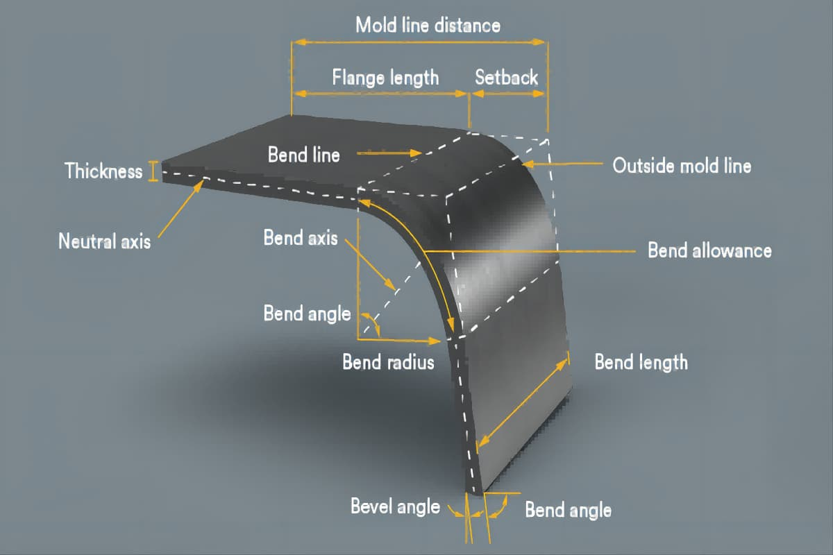
The bend radius refers to the distance from the bend axis to the surface of the sheet or bar when it is bent — this is typically referred to as the internal radius.
This internal curve is critical to both the structural integrity and visual quality of the finished part. The external bend radius is generally equal to the internal bend radius plus the sheet thickness.
- Internal Bend Radius (Ir): The curvature on the inside of the bend, serving as the essential reference point for all subsequent calculations, such as bend allowance and K-factor determination.
- External Bend Radius (Or): Equal to the internal radius plus the material thickness (T), or Or = Ir + T.
While people often talk about bend radius, two critical — and often confused — concepts define whether a design will succeed or fail:
(1) Minimum Bend Radius
This is the physical limit of a material: the smallest internal bend radius achievable without causing cracks or fractures on the outer surface.
The value is dictated by the material’s ductility, hardness, and thickness. Pushing this limit is like walking on the edge of a cliff — while it might be physically possible, it creates severe stress concentrations at the bend that become hidden structural weak points, primed for future failure.
(2) Optimum Bend Radius
The optimum bend radius reflects the craft’s true mastery — a balance between quality, structural strength, dimensional stability, and economic efficiency. Industry consensus often places this sweet spot at roughly Ir ≈ T.
At this ratio, stress distribution across inner and outer layers is most uniform, the bending process remains stable, springback is minimized, and angle consistency is at its best. Choosing this optimum isn’t just about making it work — it’s about making it right, directly impacting product reliability and profitability. To understand how to achieve this balance in practice, you can refer to the Guide to Press Brake Bending or request our detailed brochures for tooling and radius guidelines.
2.2 Why Bend Radius Matters
The bend radius is far more than a simple geometric measurement; it is a first-principle factor that influences design, process feasibility, and cost efficiency from the ground up.
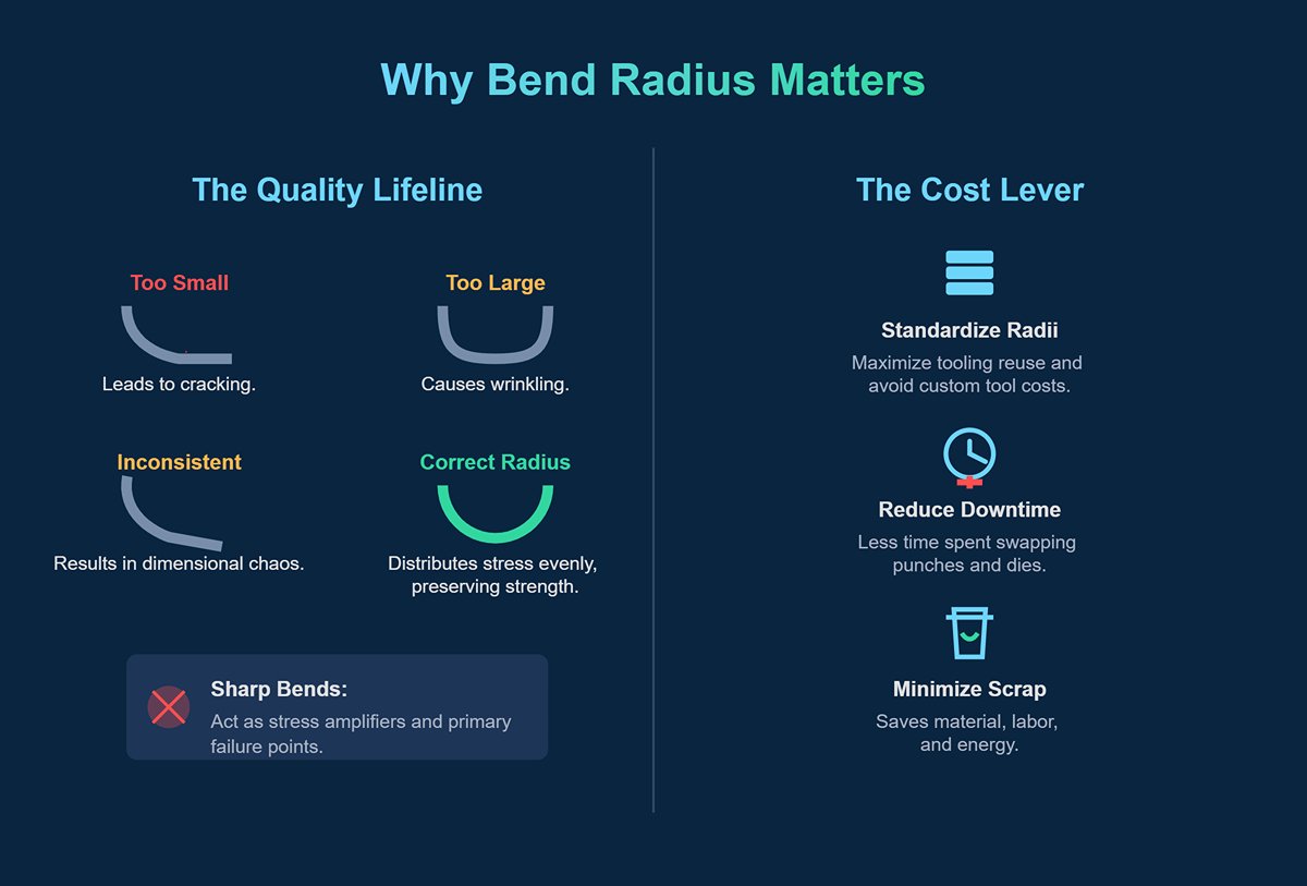
(1) The Quality Lifeline
Choosing a bend radius is effectively a pledge to the quality of your product.
An improper radius is the root of countless problems: too small, and you risk cracking; too large, and you get wrinkling; inconsistent, and you invite dimensional chaos and assembly nightmares. A well-chosen radius evenly distributes stress, preserving strength, while a sharp bend acts as a stress amplifier — often becoming the first point of failure under vibration or loading.
(2) The Cost Lever
Your profit margin often hides in your bend radii. Standardizing bend radii in your designs allows maximum reuse of existing tooling, avoiding the need for expensive, custom punches and dies for a handful of unique parts.
This not only reduces tooling costs but also significantly cuts down the downtime spent swapping out dies and punches — one of the largest hidden costs in modern manufacturing. The use of an advanced NC Press Brake can further enhance flexibility while keeping expenses under control.
Furthermore, a rational radius helps minimize scrap rates, saving material, labor, and energy.
(3) Process Feasibility
Bend radius defines the line between creative vision and practical execution. It is the first “gatekeeper” determining whether a designer’s concept can leave the CAD screen and reach the shop floor.
For example, high-strength steel is far less ductile than soft aluminum, meaning it requires a much larger bend radius to be formed safely. Any design that ignores these physical realities — no matter how clever — will remain an unbuildable drawing, inevitably scrapped at the production stage.
2.3 The Inner Logic of Bend Radius
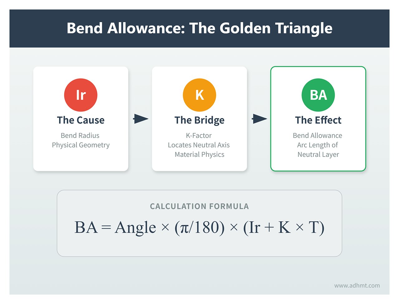
To truly master bend radius, you must understand its intrinsic connection to two other core concepts: bend radius, K-factor (neutral axis), and bend allowance — together forming an interdependent "golden triangle."
(1) Bend Radius – The “Cause”
This is the design input — the starting point. The internal bend radius (Ir) is chosen based on function, strength, and aesthetics. This geometric decision initiates the entire chain of logic.
(2) K-Factor / Neutral Axis – The “Bridge”
When metal bends, the outer surface stretches while the inner surface compresses. Between them lies the neutral axis — a plane that, in theory, experiences no change in length.
In reality, because compression is easier than tension, the neutral axis shifts from the exact mid-thickness (50% position) toward the inside of the bend. The K-factor quantifies this shift, serving as the bridge between design intent and physical reality.
It is defined as the ratio between the distance from the neutral axis to the inner surface (t) and the total material thickness (T): K = t / T.
(3) Bend Allowance – The “Effect”
This is the final outcome that guides production. Once we know the bend radius (Ir) and use the K-factor to locate the neutral axis, we can precisely calculate the actual arc length along the neutral layer in the bend region — the bend allowance (BA).
The formula is: BA = Angle × (π/180) × (Ir + K × T)
The golden triangle’s logic is crystal clear: the bend radius (cause), combined with the material’s bending physics (described by the K-factor bridge), ultimately determines the bend allowance (effect) for accurate blank sizing.
A well-organized Bend Allowance Chart can be an invaluable tool for saving time and ensuring precision.
Ⅲ. Cognitive Reconstruction: The Bend Radius — The Hidden Lever Behind Sheet Metal Profitability
On an engineering drawing, the bend radius might appear as nothing more than a modest arc annotation. Yet, on a company’s balance sheet, it’s the invisible gatekeeper of profit. Most catastrophic failures in sheet metal manufacturing—from misaligned welding fixtures to entire batches of scrapped parts—rarely stem from complex assembly logic. Rather, they originate from a fundamental misunderstanding of the “radius–flat pattern–tolerance” chain reaction. To truly master press brake operations, one must first reconstruct the physical and economic understanding of the bend radius.
3.1 Beyond Geometry: The Economic Logic of Bend Radius
The bend radius is far more than a geometric dimension—it is the key variable that determines the final accuracy of a sheet metal part. Overlooking it often leads directly to financial losses.
- The Yield Domino Effect: The core of sheet metal fabrication lies in flat pattern calculation. The precision of the flat blank depends heavily on the K-Factor and bend deduction, both of which are direct functions of the bend radius. In air bending, if the naturally formed inside radius (Ir) differs from the design intent (for example, design R = T, but actual R = 1.2T), a tiny deviation arises in the developed length. While a single bend may only be off by 0.1 mm, the cumulative effect across multiple bends can lead to significant dimensional errors, making assemblies unfit for welding and resulting in full-batch rejection.
- The Cost Trap of Chasing the “Perfect Radius”: Pursuing ultra-small radii or overly tight tolerances as shown on drawings can be prohibitively expensive. Studies show that narrowing bending tolerance from a standard ±0.5mm to ±0.1mm can raise production costs by 25%–40%; tightening it further to ± 0.05mm may increase costs by 5 to 8 times. Extremely small radii result in faster die wear, higher press tonnage requirements, and more frequent recalibration.
- The Iron Rule: Inside Radius (IR) vs. Outside Radius (OR): This is a common source of drawing errors. The physical law is simple—the outside radius always equals the inside radius plus material thickness (OR = IR + T). Inexperienced designers often label the outside radius on drawings, causing confusion on the shop floor. Workshop Rule: All bend calculations, die selections, and process parameters must be based solely on the inside radius (IR).
3.2 The Physical Truth Behind the Natural Radius
In modern sheet metal manufacturing, air bending is the dominant technique. A counterintuitive truth about this process is that the final bend radius is not determined by the punch tip radius.
- The “20% Rule” and Floating Nature of Air Bending: In air bending, the sheet contacts only the two shoulders of the V-die and the punch tip, creating a free-floating parabola governed by physical laws. The defining factor of this “natural radius” is not the punch, but the V-die opening width (V).
- The Sharp Bend Threshold: When the punch tip radius falls below 63% of the material thickness, a “sharp bend” phenomenon occurs. Here, the punch acts less like a forming tool and more like a blade, cutting into the material surface and creating a crease. This destroys the parabola relationship, invalidates standard flat pattern formulas, and can cause compression fractures along the neutral line—severely weakening structural integrity.
- Neutral Axis Drift: During bending, the inner fibers of the material compress while the outer fibers stretch. The neutral axis—where no tension or compression occurs—shifts inward from the material’s midpoint. The tighter the radius, the greater the stress concentration and the smaller the K-Factor (down to 0.33). With larger radii, the K-Factor gradually returns to around 0.5. Understanding this shift is essential for accurate flat pattern calculation.
3.3 The Key Variable Matrix: The “Triad” That Governs Bend Radius
Achieving zero-trial bending requires the precision of a chemist—balancing three critical factors: material properties, die geometry, and grain orientation.
- Material DNA: Tensile Strength Determines Springback and Radius: Harder materials with higher tensile strength yield greater springback, which in turn produces larger natural bend radii.
- Comparison Example: Using the same V-die, stainless steel will form a noticeably larger radius than low-carbon steel. As a result, stainless steel demands greater over-bending angles to offset springback and often requires smaller V-die openings to control radius expansion.
- Die Geometry: The Logic Behind V-Die Selection:
- Standard Rule: For low-carbon steel, the V-die opening width is typically 8 times the material thickness (V = 8T).
- High-strength steel and thick plate: To prevent cracking and accommodate a larger natural radius, use dies with openings of 10T or even 12T.
- Soft aluminum: Because the material is ductile, tighter radii can be achieved using a smaller die width, around V = 6T.
- Grain Direction: The Invisible Breakage Trigger: Rolled sheet metal has a fiber-like structure similar to wood grain. Recognizing and utilizing this orientation marks the dividing line between novice and expert.
- Across the Grain Bending: The optimal practice—where the bend is perpendicular to the grain. The material exhibits maximum ductility, allowing the smallest bend radii (about 1T) without cracking.
- With the Grain Bending: Highly risky. Stress accumulates along the grain boundaries, making tears very likely. If grain-parallel bending is unavoidable for layout reasons, increase the bend radius (at least 1.5T~2.5T) or locally anneal the material. Ignoring grain direction is one of the leading causes of cracking in high-strength aluminum alloys such as 6061-T6.

Ⅳ. Algorithm and Engineering Logic: Building a Zero-Trial-and-Error Calculation Model
Moving beyond “rule of thumb” and “trial-and-error” marks a turning point in modern sheet metal fabrication. In the realm of precision manufacturing, the bend radius should never be a matter of chance—it is an engineering variable that can be accurately calculated, predicted, and controlled. This chapter unveils the mathematical logic hidden behind metal deformation, enabling you to construct a closed-loop computational model that connects CAD design seamlessly to shop-floor execution.
4.1 The Golden Rule: Accurate Calculation of Air Bend Radius
A common misconception in air bending is that the punch radius determines the part’s inner radius. In reality, the V-die opening width is the true master variable that governs the resulting inner radius (Ir). Air bending is a natural forming process based on the physics of “three-point bending.”
The 20% Rule: Functional Relationship Between V-Die and Bend Radius
As the punch descends to a set depth, the sheet naturally forms a parabolic curve across the two shoulders of the V-die. Extensive experimental analysis shows that the material’s tensile strength directly determines this proportional relationship—summarized as the “20% Rule” and its material-specific variants:
Mild Steel (~60 KSI): Follows the 16% Rule.
Formula:
Application: This serves as the primary reference for most standard bending operations.
Stainless Steel (304/316, ~90 KSI): Follows the 18–20% Rule.
Formula: Ir≈0.18~0.20xV
Physical logic: Higher yield strength causes stronger springback, naturally enlarging the bend radius. Under the same V-die, stainless steel produces a larger radius than mild steel.
Soft Aluminum (5052-H32, ~30 KSI): Follows the 12–15% Rule.
Formula: Ir≈0.12~0.15xV
Physical logic: A softer material conforms better to the die, producing a tighter bend radius.
Thickness Segmentation Strategy: Breaking the “One-Size-Fits-All” Approach
Relying solely on percentage rules is insufficient; bend strategy must also adapt to sheet thickness (T):
| Thickness Range (mm) | Recommended Strategy | Calculation Logic | Notes |
|---|---|---|---|
| T < 6mm | Equal-Thickness Rule | Ir = T | Choose V = 6T–8T; K-factor ≈ 0.42–0.45, yielding standard bending accuracy. |
| 6mm < T < 12mm | 1.5× Rule | Ir = 1.25T–1.5T | Increase V to 8T–10T to reduce tonnage and prevent machine overload. |
| T > 12mm | Multiple Rule | Ir = 2T–3T | Use V = 10T–12T with large-radius punches to prevent cracking. |
4.2 Defining the Limits: Minimum Bend Radius and the Sharp-Angle Trap
A common hazard in design is the pursuit of compact geometry through ultra-tight radii—an approach that risks triggering two “landmines” at the physical limits: the minimum bend radius and sharp-angle bending.
Minimum Bend Radius
This represents the red line of a material’s physical capacity. Once the bend radius drops below this threshold, the outer fibers stretch beyond their elongation limit, leading to micro-cracking or full fracture.
- Safety Factor Recommendation: Use a 1.5× safety margin in design. For example, if data indicates a minimum radius of 1T for a given aluminum alloy, specify 1.5T on the drawings. This compensates for batch variability and grain direction effects—especially critical for 6061-T6 aluminum, which almost always cracks when bent along the grain unless the radius exceeds 3T.

Sharp Bends and the “63% Trap”
Even seasoned engineers sometimes overlook this subtle but critical issue.
- Definition: When the punch radius (Rp) is less than 63% of the material thickness (Rp < 0.63T), the bending mechanism shifts fundamentally.
- Consequence: The punch ceases to “bend” the material and instead “cuts” into it like a blade, forming a permanent crease.
- Flattening Failure: Conventional bend allowance formulas assume an arc profile. Once a crease is formed, this assumption collapses and produces large bend allowance (BA) calculation errors.
- Structural Damage: Intense compression along the neutral axis thins the material at the bend, severely reducing load capacity.
- Solution: If the design specifies an extremely tight radius (e.g., R = 0.5T), use coining or a larger-radius punch to achieve the desired result, rather than forcing it through air bending.
4.3 Data Feedback Loop: Reverse Engineering the K-Factor
The essence of precision manufacturing lies in a closed-loop data cycle—using real-world measurements to refine design assumptions. Avoid relying on default K values like 0.5 or 0.44; these are for general estimation, not high-precision production.
The Three-Step Reverse Engineering Protocol
To establish an enterprise-grade, high-accuracy bending database, follow this standardized process:
Prepare Standard Samples: Cut three precisely dimensioned rectangular test coupons (e.g., 100mm × 50mm), marking clear bend lines on each.
Perform Controlled Bending and Measurement:
- Use the standard V-die and punch combinations employed in the workshop.
- Perform a 90° air bend.
- Critical Measurements: Use a radius gauge or optical projector to accurately measure the actual inner radius (Ir)—never assume it equals the punch radius. Also measure both leg lengths (L1, L2) after bending.
Back-Calculate the K-Factor: Apply the inverse of the flat pattern formula. With known total flat length (Ltotal) and formed dimensions, compute the bend deduction (BD) via BD=(L1+L2)-Lttal. Using the measured BD and actual Ir, solve for the K-Factor through CAD software or Excel for that specific die and punch setup.
Digital Synchronization: Implementation in SOLIDWORKS / SheetWorks
Organize the collected empirical data—linking sheet thickness, tooling configuration, actual measured radius, and K-factor—into a Bending Process Table (Gauge Table / Bend Table), then import it into your CAD software.
- Value: When a design engineer selects “3mm stainless steel” with a “V16 die” in SOLIDWORKS, the system automatically references the measured values Ir = 3.2mm and K = 0.46 for flat pattern calculations.
- Result: The unfolding accuracy improves dramatically from ±0.5mm to ±0.05mm, realizing true “design-to-production” precision and eliminating the inefficiency of repeatedly grinding dies or adjusting backstops just to meet dimensions.
Ⅴ. Hardware and Process Strategy: Tooling Selection and Parameter Optimization
If algorithms are the “brain” of the bending process, then tooling is its “skeleton.” On the shop floor, many issues such as uncontrollable bending radii, cracking, or unstable angles often stem not from operator skill but from mismatches between tooling choice and material properties. This chapter establishes a systematic framework for hardware decision-making—moving you from trial-and-error methods to logic-driven tooling selection.
5.1 Tooling Decision Matrix
Many workshops adhere rigidly to the simple rule “V = 8T” (V-die width equals eight times the sheet thickness). While this works for medium-thickness low-carbon steel, such one-size-fits-all thinking becomes problematic when dealing with complex materials or demanding radii. A dynamic decision matrix is needed.
1. The Dialectic of V-Die Selection: Beyond the ‘8× Rule’ Choosing the right V-die width means finding the optimal balance between tonnage load, formed radius, and flange length.
- Standard Range (V = 8T): Suitable for low-carbon steel up to 6mm thick. This air-bending baseline typically produces an internal radius roughly equal to the material thickness (Ir ≈T) while maintaining moderate tonnage requirements.
- Tight Strategy (V = 6T): Used when a smaller bend radius is required (e.g., for aluminum) or when the minimum flange length is limited (flange length < 4T).
- Caution: This approach increases required tonnage by roughly 20–30% and tends to leave pressure marks on softer materials.
- Expanded Strategy (V = 10T ~12T): Recommended for high-strength steels (HSS), stainless steels, or thicker materials (>6mm).
- Rationale: Harder materials experience greater springback, so a wider V-die allows for natural radius formation while significantly reducing tonnage—protecting both the press and the tooling from damage.
2. Punch Matching Principles: Avoiding the “Digging Effect” In air bending, the punch tip radius (Rp) does not solely determine the internal radius, but proper matching is critical.
- Preventing the Digging Effect: If the punch radius is much smaller than the naturally formed inner radius (for example, using an R1 sharp punch to bend a plate with a natural R5 radius), the punch acts like a wedge—penetrating the material, thinning the bend bottom, and leaving deep, hard-to-remove creases.
- Best Practice: The punch radius should be slightly smaller than or equal to the natural radius, but never less than 63% of the material thickness to avoid sharp-angle failures.
- Heavy-Duty Bending Strategy: For high-strength steels or thick plates, use a large-radius punch (Radius Ruler). For example, when forming Hardox wear plates, the punch radius often needs to be 3T or greater to distribute stress effectively and prevent material cracking or costly die damage.
3. Western Tooling Philosophies
- American-Style Tooling: Typically features a 90° symmetric design—durable and simple, ideal for general-purpose bending. However, it struggles with high-springback materials because it cannot provide enough “over-bend” compensation.
- European-Style Tooling: Usually designed with sharper 88° or 86° openings and offset mounts. This configuration is optimized for precision air bending, allowing sufficient angular compensation—making it the preferred choice for stainless steel and high-strength applications.
5.2 Deep Dive: Springback Control
Springback is an unavoidable physical law of elastic deformation—the larger the bend radius, the greater the rebound. In essence, mastering bend radius control means precisely predicting and compensating for springback.
1. Springback Prediction Model Physics tells us:
This means that a higher R/T ratio (larger bend radius relative to thickness) and higher yield strength both lead to greater springback angles.
- Low-Carbon Steel: Under standard V=8T, springback is typically 0.5°-1°.
- Stainless Steel (304): Springback can reach 2°-3°.
- High-Strength Steel (Domex/Hardox): Extremely pronounced springback of 5°-15°. To achieve a final 90° bend, the forming angle may need to be as tight as 78° or less.
2. Dual Compensation Strategies
Angle Compensation: The most straightforward approach—use a sharper-die angle (e.g., an 86° V-die) along with CNC Y-axis depth adjustments to intentionally “over-bend.”
Formula Reference:
Radius Compensation: Often overlooked. When springback occurs, not only does the bend angle open up, but the internal radius also increases. Die wear amplifies this effect.
Practical Tip: In CAD flat-pattern calculations for high-springback materials, input a radius 5–10% larger than the target, or reduce the V-die width (within tonnage limits) to compensate by tightening the radius mechanically.
5.3 Special Techniques and Automation
When standard tooling cannot meet specific design demands, advanced forming methods and modern automation technologies must be introduced.
1. Bump Bending (Step Bending)
How can a large-radius curve of R = 200,mm be formed using a standard die? The answer lies in bump bending.
Core Principle: Break down the large arc into dozens of small, incremental bends.
Key Calculations:
Step Pitch: It’s recommended to keep the spacing within 2mm ~ 5mm, or an angular increment of 1.5°~2°. Excessive pitch may cause visible facets—the so-called polygonal effect.
Chord Length Formula:
Die Selection: Use a narrow V-groove to ensure the sheet rests securely on both shoulders during each press, preventing it from slipping into the die bottom.
2. Mark-Free Bending Technology
For mirror-finished stainless steel or aluminum components, any indentation from the V-die shoulders is unacceptable.
- Urethane Dies: A high-hardness urethane pad serves as the lower die, and hydraulic pressure allows the sheet to form smoothly, eliminating surface marks entirely. However, the trade-offs include shorter die life and significantly higher tonnage requirements.
- Roller V-Dies: The shoulders of the lower die are fitted with rotating rollers that convert sliding friction into rolling contact. This not only prevents scratches but also reduces bending force by about 20%, making it the best investment for protecting high-value parts.
3. CNC Parameter Optimization and Laser Correction
Modern high-end press brakes (such as Amada or Trumpf) now integrate material databases and adaptive control systems.
- Laser Angle Correction (LCS/IRIS): The ultimate tool for compensating springback variation. Sensors continuously measure the bending angle in real time (accuracy up to pm 0.1°) and automatically adjust the ram depth. This eliminates deviations caused by batch-to-batch material differences, ensuring a perfect first-piece result every time.
- Adaptive Database: Build a dedicated material library that stores correction data from each run. Over time, the machine "learns," automatically selecting the optimal K-factor and springback compensation for materials like 2.0mm 304 stainless steel.

3. Hole Deformation Near Bend Lines
When holes are placed too close to a bend line, tensile forces during bending can distort them into an oval shape, preventing proper screw installation.
- Minimum Distance Rule: The distance from the hole edge to the bend line D must satisfy D≥1.5 ×T+R (R being the inside bend radius).
- Remedies:
- Relief Cuts: Create elongated or half-round relief holes along the bend line to break the stress transfer path.
- Bend Before Punching: Reverse the process order—perform bending first, then punch or laser-cut the hole positions. Although more expensive, this yields the highest accuracy.
5.4 Punch tip radius
The punch tip radius determines how the material takes shape during bending and how it interacts with the die. Whenever possible, match the punch tip radius to the natural internal radius created by the die’s V-opening to achieve consistent angles and minimize tooling wear.
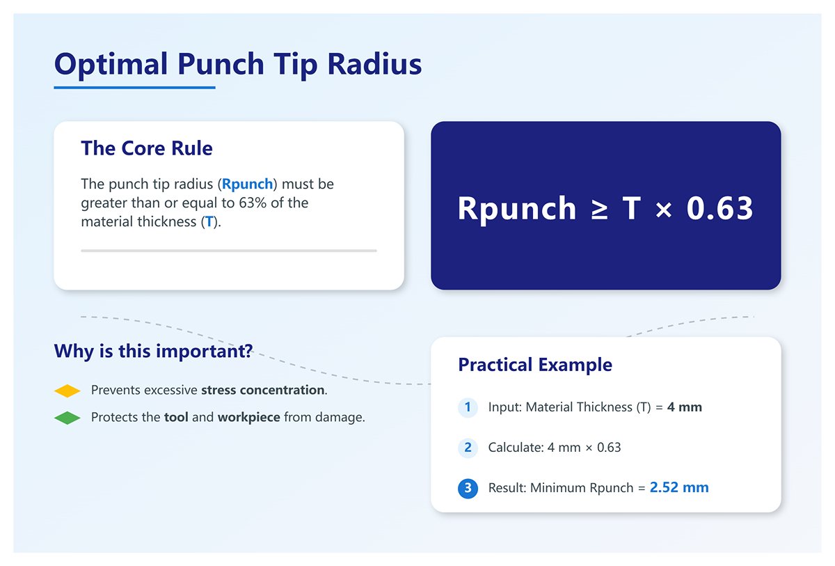
(1) Optimal punch tip radius:
The punch radius should be at least 63% of the material thickness to prevent excessive stress concentration, which can damage both the tool and the workpiece.
For example, for a sheet with thickness T = 4 mm, the minimum punch tip radius should be:
(2) Interaction with material properties:
- If the punch tip radius is too small, it can pierce harder materials such as stainless steel, causing surface defects or premature tool wear.
- If it’s too large, it may interfere with the natural bend radius, resulting in inconsistent outcomes.
Best practice:
As far as possible, match the punch tip radius to the natural internal radius produced by the die’s V-opening to ensure consistent angles and minimal die wear.
5.5 Bending methods
The specific bending method chosen has a direct effect on the achieved bend radius. In press brake operations, the two main techniques are air bending and bottom bending, each offering distinct characteristics that affect the radius.
(1) Air bending
The sheet only contacts the punch and die edges, so the bend radius is less dependent on the punch and die geometry, material thickness, and press brake settings. It allows a range of radii but requires compensation for springback.
(2) Bottom bending
Forces the material to fully seat against the die, producing an accurate and consistent bend radius with tighter tolerances. This method places higher demands on press tonnage and tooling stress, making it ideal for precise, repeatable results.
(3) Coining
Applies extremely high pressure to press the punch tip into the material, achieving the most precise bend radius. It is resource-intensive and used for ultra-precise radii and minimal springback.
| Characteristic | Air Bending | Bottom Bending | Coining |
|---|---|---|---|
| Radius determinant | V-opening width (primary) | Punch tip radius (primary determinant) | Punch tip radius (absolute determinant) |
| Accuracy & consistency | Moderate, heavily affected by springback | High, minimal springback | Extremely high, virtually no springback |
| Required tonnage | Low | Medium–high (above air bending) | Very high (up to 5–10× air bending) |
| Flexibility | Very high — one tool set can produce multiple angles | Low — die angle must match part angle | Very low — tooling custom-made for specific angles & radii |
| Impact on tooling/equipment | Minimal wear, low pressure | Higher wear and pressure | Severe wear, demands maximum machine rigidity |
| Core challenge | Controlling springback accurately | Managing tonnage to avoid overpressing into coining | Extremely high tonnage requirements and high tooling costs |
| Typical applications | Most general sheet metal work, high-flexibility scenarios | Batch production needing high precision & consistency | Special applications seeking sharp corners or ultra-high precision |
Interaction with Material Properties:
- If the punch tip radius is too small, it can penetrate into harder materials like stainless steel, causing surface defects or premature tool wear.
- If it is too large, it may dominate the natural bend radius, leading to inconsistent results.
Best Practices:
- Match the punch tip radius as closely as possible to the natural inside radius produced by the die V-opening for consistent angles and minimal wear on tooling.
Ⅵ. Practical Field Guide: Common Issues and Solutions
Theoretical formulas are just the starting point—true mastery is forged on the shop floor. In production, 90% of quality defects don’t arise from calculation errors but from the dynamic imbalance of the “Golden Triangle”: machine precision, die condition, and material variation. This chapter focuses on practical diagnostic frameworks and solutions that help you move from reactive troubleshooting to proactive process mastery.
6.1 Quality Defect Diagnosis and Troubleshooting
When scrap parts appear, randomly tweaking parameters is the worst possible reaction. Always follow a “Symptom–Root Cause–Resolution Path” approach.
1. Outer-Side Cracking
This is the most critical defect when bending high-strength materials, often showing as fine hairline fractures or complete breakage along the outer bend.
- Root Cause: The tensile strain on the outer fibers exceeds the material’s elongation limit. Simply put, the bend radius is too small for the material’s physical limits.
- Corrective Actions:
- Increase Radius (Preferred Solution): Switch to a wider V-die (e.g., from V = 8T to V = 10T) to naturally enlarge the inner radius and reduce tensile strain.
- Adjust Grain Direction: Ensure the bend line runs across the grain of the rolled sheet. If bending parallel is unavoidable, increase the radius by 1.5 to 2 times.
- Material Pre-Treatment: For extremely hard alloys like 7075-T6, perform localized annealing along the bend line to soften the region before forming.
2. Orange Peel Effect
The outer bend surface develops a coarse, grainy texture that, while mechanically harmless, severely compromises the appearance of visible parts.
- Root Cause: Excessive bend radius or coarse-grained material causes crystal slip and rotation during deformation, resulting in a roughened surface.
- Corrective Actions:
- Tighten the Radius: Orange peel usually appears in large-radius bends; minimize the radius as much as possible without inducing cracks.
- Material Selection: Choose fine-grain sheet stock or materials specifically designed for deep drawing and bending applications.
- Surface Treatment: If unavoidable, add a polishing step after bending or apply textured surface finishes beforehand to mask the defect.
3. Angle Inconsistency
In the same batch, parts set at 90° may come out anywhere between 89° and 91°.
- Root Cause: Beyond machine repeatability, two hidden culprits are thickness tolerance and deflection compensation failure.
- Corrective Actions:
- Thickness Grouping: Even minor variations (e.g., 2.9mm vs. 3.1mm) can cause significant angular deviation. For precision parts, measure each sheet before production and group them within a ±0.05mm range.
- Crowning Calibration: If angles are greater in the center and smaller at the ends, increase the machine’s deflection compensation. Conversely, reduce it if the opposite occurs.
6.2 Material-Specific Best Practices
Each metal type has a distinct “personality,” and applying one-size-fits-all bending parameters can easily lead to failure.
1. Stainless Steel (304 / 316)
- Pain Points: High springback, galling tendency, and scratch-prone surfaces.
- Best Practices:
- Protective Separation: Always use sheets with PVC/PE protective films or lay urethane film over the lower die to prevent direct contact that causes galling and scratches.
- High-Pressure Strategy: Because of significant work hardening, aim for one-pass forming to avoid repeated pressing.
- Parameter Adjustment: Apply 2°~3° of overbending and choose a V-die width between 10T~12T to distribute pressure more evenly.
2. Aluminum
- Pain Points: Large variations in hardness across grades; prone to cracking or surface denting.
- Practical Strategies:
- Alloy Warning: 5052-H32 is the preferred choice for bending due to its excellent ductility, while 6061-T6 is extremely brittle and prone to cracking when the bend radius is small (R < 2T).
- Special Case for 6061-T6: If the design requires 6061 and a small radius, specify the material in the T4 condition at purchase, perform bending first, and then heat-treat it to T6. Alternatively, set the bend radius to at least 3T.
- Preventing Surface Marks: Because aluminum is very soft, choose a V-die with a large shoulder radius or use a non-marring die set to prevent surface indentation.
3. High-Strength Steel and Wear-Resistant Plate (HSS / Hardox / Weldox)
- Pain Points: Extremely high tonnage requirements, high risk of cracking, and potential die breakage.
- Practical Strategies:
- Safety First: Never use a regular small-radius punch. The punch radius must be larger than the sheet thickness (recommended Rp = 3T to 4T).
- Wider V-Die: Set the V-die opening to 12T or even 16T.
- Slow Operation: Reduce the ram speed to less than 20% of normal speed to allow the material’s internal lattice to rearrange gradually, preventing sudden fracture.
6.3 Challenges of Complex Geometries
When designs move beyond simple L- or U-shapes into more complex features, standard bend rules often fail due to interference and deformation.
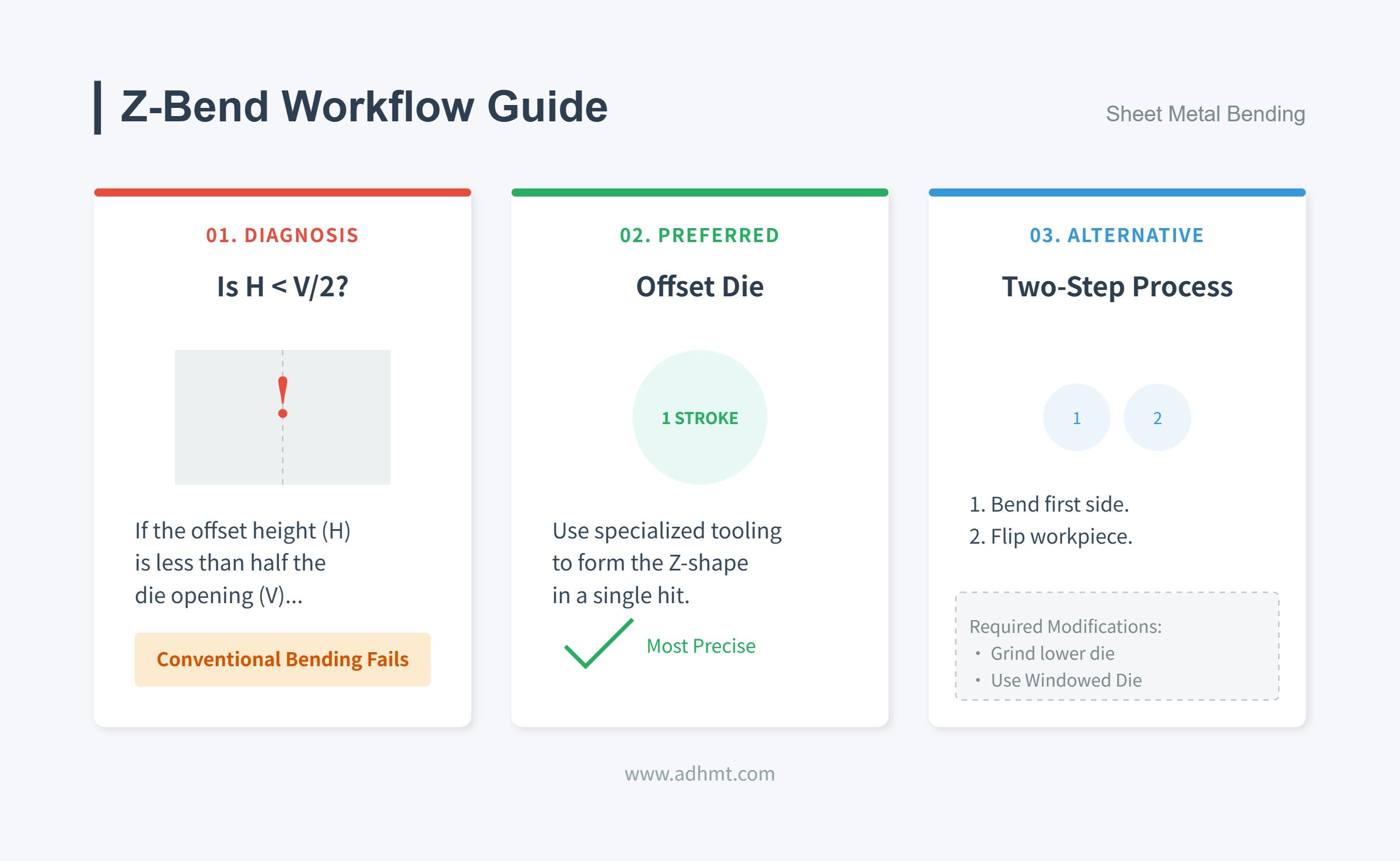
1. Z-Bends (Offsets)
When two bends are very close together, the sheet can collide with the lower die after the first bend, causing interference.
- Evaluation Standard: When the spacing between the two bends H < V/2, conventional air bending cannot be performed properly.
- Solutions:
- Use an Offset Die: This special tooling performs both bends in one stroke, forming a precise Z-shape.
- Two-Step Process: First make one bend, then flip the workpiece. If interference remains, grind the back side of the lower die (to remove the interfering area) or use a custom windowed die.
2. Hemming and Flattening
Commonly used for edge reinforcement or to eliminate sharp edges.
- Risk Point: During the second flattening step, the outer layer at the bend undergoes extreme compression and can easily crack.
- Practical Tips:
- Teardrop Hem: Avoid fully flattening the hem. Leave a tiny gap in the middle (forming a teardrop shape). This greatly reduces the risk of cracking and preserves hinge integrity.
- Control of Pre-Bend Radius: During the first sharp bend (around 30°), the smaller the radius, the less tonnage is required in the second flattening step—but the higher the risk of cracking. Achieving balance between the two is key.
Ⅶ. Press Brake Bend Radius Calculation
The 8 times rule is a general guideline for determining the V-shaped die opening, suggesting that the V-die opening should be 8 times the material thickness. However, there is no exact formula for determining the ideal bend radius for sheet metal, but under certain specified force conditions, the bend radius can be estimated to be equal to the thickness of the plate.
It's important to note that changes in the material thickness will affect the accuracy of this estimation. The V-shaped die opening may range from 6 to 12 times the material thickness. The bend radius is closely related to the material thickness. For material thicknesses less than 6mm, the bend radius is equal to the material thickness.
For material thicknesses greater than 6mm but less than 12mm, the bend radius is typically 1.5 times the material thickness. For material thicknesses greater than 12mm, the bend radius is approximately 3 times the material thickness.
The press brake bend radius can be calculated using the formula, all in millimeters:
- R is the bend radius
- V is the V-opening width of the die
- MT is the material thickness
For example, if the V-opening width is 50 mm and the material thickness is 5 mm, the bend radius would be:
It's important to keep in mind that these are just rough guidelines and there are many factors that can impact the bend radius, making it challenging to determine an exact number.
When the sheet thickness is equal to the bend radius, the most ideal bend radius is achieved. The bend formed with this radius is consistent in angle and size and has minimal springback.
5.1 What Is the Minimum Bend Radius of Sheet Metal in Press Brake Operations?
If the bend radius is smaller, the stress on the outside of the bend will be greater and the tension will be greater. The plate will be deformed, cracked, or broken during bending. In order to avoid these problems, attention should be paid to the minimum bending radius.
Due to different bending methods, die and material characteristics, different workpieces may have different minimum bending radii, and it is difficult to calculate the correct value. However, in order to obtain the most perfect bending workpiece, the inner radius should be set as close to the plate thickness as possible.
To select plates with high ductility, the greater the tensile strength and hardness of the material, the larger the radius is required.
5.2 What Is the Formula for Bend Deduction and Bend Allowance?
Bend deduction refers to the amount of stretching that occurs during bending. It is calculated as the difference between the total length of the flange and the total flat length.
Given:
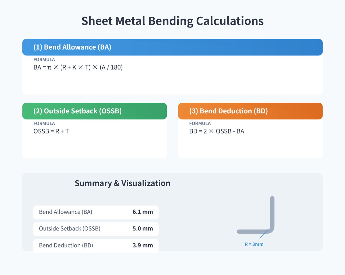
- Material: Stainless Steel
- Thickness (T): 2 mm
- Inside Bend Radius (R): 3 mm
- Bend Angle (A): 90°
- K-Factor (K): 0.44
Step-by-Step Calculation:
(1)Calculate Bend Allowance (BA)
The formula for Bend Allowance is:
Plugging in the values:
(2) Calculate Outside Setback (OSSB)
The formula for Outside Setback is:
Plugging in the values:
OSSB=3+2
OSSB=5 mm
(3) Calculate Bend Deduction (BD)
The formula for Bend Deduction is:
Plugging in the values:
(4)Summary:
- Bend Allowance (BA): 6.1 mm
- Outside Setback (OSSB): 5 mm
- Bend Deduction (BD): 3.9 mm
(5) Application:
To achieve a 90° bend with a 3 mm inside bend radius on a 2 mm thick stainless steel sheet, you need to set the bend deduction to 3.9 mm during the bending process. This means you need to over-bend the sheet by 3.9 mm to compensate for the springback after bending, ultimately achieving the desired 90° bend angle.
(6) Practical Example:
Suppose you have a sheet metal part with two flanges, each 40 mm long, and a 100 mm base. The total length before bending is:
After accounting for the bend deduction:
Therefore, the flat pattern length should be 172.2 mm to achieve the desired dimensions after bending.V. Common Mistakes and Advanced Applications in Press Brake Operation
5. Management and Efficiency: From Workshop to Financial Statements
After mastering the physical mechanics and calculation formulas, the final battleground for bending processes lies in management. For business owners and production managers, the bend radius is not just a geometric parameter—it’s a critical link between shop-floor efficiency and financial performance. A poorly controlled radius system leads to higher scrap rates, longer setup times, and unpredictable die wear. This chapter shifts from a purely technical view to an ROI-based management framework.
5.1 Cost Optimization Model (ROI Analysis)
The hidden sinkhole of bending cost often lies in decisions that seem cost-effective. Building a precise ROI model helps quantify how technological investments leverage profitability.
1. Tooling Investment vs. Scrap Loss: The Premium of Precision Many workshops still rely on low-cost Cold Planed Dies, typically with hardness around HRC 32–34 and linear accuracy of ±0.038mm/m. While inexpensive initially, their poor consistency and wear resistance cause up to ±2° angular drift per meter, forcing frequent shim adjustments and rework rates exceeding 15%. In contrast, Precision Ground Dies cost 2–3 times more upfront but achieve hardness of HRC 56–58 and linear accuracy within ±0.013mm/m.
- ROI Example: Suppose a factory scrapped two 10-foot stainless sheets each week due to unstable angles or test runs (each sheet costing $100). Annual scrap losses exceed $10,000. Precision dies not only last 3–5 times longer but also pay back their price difference within 12–18 months through reduced waste. More importantly, their perfect segment alignment (tolerance < 0.01 mm) eliminates visible steps in multi-section bending.
2. The Profit of Standardization: The Art of Simplification Designers often specify arbitrary radii—R2.5, R3.2, R4.0—and inadvertently force frequent die changes on the production floor.
- Strategy: Enforce “radius standardization.” Restrict non-critical bends to a few common radii (e.g., thin sheets: R1.0, medium sheets: R3.0, thick sheets: R6.0).
- Benefits: Cut average die-change time from 30 minutes to 15. At four changes per day, that frees about 48 hours of core capacity per year—saving thousands of dollars in labor while reducing tooling storage and management overhead.
3. Design-to-Cost: Eliminating Nonstandard Expenses at the Source The most expensive radius is the one your workshop can’t produce. Bridging the gap between design and manufacturing is essential.
- Implementation: Standardize your shop’s existing die parameters (V-die widths, measured internal radii) into a Gauge Table, then import it directly into CAD software such as SolidWorks or Pro/E.
- Result: By accessing the existing die parameters directly during modeling, designers enable the system to automatically calculate precise bend deductions (BD). This eliminates the need for custom non-standard dies, saving approximately $2,000 per set, and shortens the design-to-mass-production cycle for new products by over 20%.
5.2 Building an Enterprise-Level Bending Knowledge Base
Bending expertise should not remain a “black box” locked in the minds of veteran technicians—it should be an asset the company can replicate. By creating a digital knowledge base, experiential know-how is transformed into data-driven processes.
1. Parameterizing Standard Operating Procedures (SOPs) SOPs should be more than a simple flowchart—they should function as detailed process recipes. Develop a reference table linking material grade, thickness, target radius, die combinations, V/T ratio, and BD values.
- Example Entry: For 2mm thick 304 stainless steel, target R=3mm → select V12 die → look up K=0.42, BD=3.3mm → apply springback compensation of 2.5°.
- Execution: Use the CNC press brake’s networking capability or a cloud-based Excel sheet to ensure all machines share the same "source of truth" data, making certain that identical parts yield the same flat patterns across different machines.
2. First Article Inspection (FAI) Standards and Upgraded Quality Tools Traditional eyeballing or rough caliper checks are no longer sufficient to meet modern tolerance demands.
- Tool Upgrades: Equip the workshop with a professional Radius Gauge set (Go/No-Go) for quick verification that radii fall within ±0.05mm. For precision components, integrate an optical comparator to assess profile deviations with accuracy up to ±0.002".
- Closed-Loop Process: Document first article inspection results following AS9102 standards (FAIR). If an out-of-tolerance radius (OOT) is found, immediately trigger a root cause analysis—whether due to die centerline shifting or variations in material hardness—rather than simply adjusting machine parameters blindly.
3. Talent Development: From Operators to Process Engineers Equipment capability sets the baseline, but human expertise determines the ceiling. Establish a three-tier talent development pathway:
- Entry-Level (Operator): Understand safety protocols, interpret basic blueprint symbols, confidently run preset programs, and handle standardized clamping setups (per FMA basic courses, with at least 6 months of experience).
- Intermediate (Technician): Grasp the logic behind bend deduction (BD) and K-factor calculations, independently disassemble basic blueprints, and use trigonometric calculations to address tooling interference (trained via Tooling U courses, capable of solving common springback issues).
- Advanced (Process Engineer): Master parametric programming and macros, employ offline simulation software for complex part scheduling, and maintain a strategic view to optimize cycle time and yield rates.
By integrating this management structure—from hardware ROI analysis to talent-driven SOPs—companies can raise sheet metal bending yield rates from the industry average of 85% to 99%, transforming the workshop from a "cost center" into a "profit engine" with core competitive value.
6. Appendix: Essential Tools for Engineers
In the fast-paced world of sheet metal fabrication, time equals money and precision is the key to survival. This section skips theory and focuses on the most practical tools of the trade. We've condensed complex physics formulas into instant-access reference charts, distilled industry best practices into downloadable templates, and pointed the way toward a digital future. These tools are designed to eliminate hesitation and trial-and-error on the shop floor, empowering every engineer and operator to make confident, expert-level decisions.
6.1 Key Cheat Sheets
The following tables are based on air bending processes and cover the most common materials and thicknesses used in the workshop. All figures are engineering estimates derived from standard physical models; actual values may require adjustment based on material batch variations (tensile strength fluctuations) and die wear. It’s recommended to print and post these tables next to the press brake control panel.
Table 1: Air Bending Gold Parameter Matrix (Metric)
Baseline rules: Mild steel V=8T; Stainless steel V=10–12T; Aluminum V=6–8T; Hardox V=12–16T
| Material Type | Thickness T (mm) | Recommended V-Opening (mm) | Estimated Inside Radius Ir (mm) | Remarks |
|---|---|---|---|---|
| Mild Steel | 1.0 | V = 8 | 1.3 | Standard V=8T, most common setup |
| (~42kg/mm²) | 2.0 | V = 16 | 2.6 | Radius ≈ 16% of V-opening width |
| 3.0 | V = 24 | 3.8 | ||
| 6.0 | V = 50 | 8.0 | Consider V=8T–10T to reduce tonnage | |
| Stainless Steel (304/316) | 1.0 | V = 10 | 1.8 | Larger V-opening required due to high springback |
| (~60kg/mm²) | 2.0 | V = 20 | 3.6 | Radius expands to 18–20% of V-opening width |
| 3.0 | V = 32 | 5.8 | Requires about 50% more tonnage | |
| Aluminum Alloy (5052-H32) | 1.0 | V = 6 | 0.8 | Softer material ensures higher conformity |
| (~25kg/mm²) | 2.0 | V = 12 | 1.6 | Radius ≈ 13–15% of V-opening width |
| 3.0 | V = 18 | 2.4 | Watch for die marking risks | |
| Wear-Resistant Steel (Hardox 450) | 6.0 | V = 80 | 18.0 | Avoid small V-openings to prevent cracking |
| (~140kg/mm²) | 10.0 | V = 120 | 30.0 | Large-radius punch (R > 3T) is mandatory |
Table 2: Tonnage Estimation Cheat Sheet
Unit: tons per meter. Based on 90° air bending.
| Plate Thickness T (mm) | V = 6T | V = 8T (Standard) | V = 10T | V = 12T |
|---|---|---|---|---|
| 1.0 | 11 | 8 | 7 | 6 |
| 1.5 | 24 | 18 | 15 | 12 |
| 2.0 | 42 | 32 | 25 | 21 |
| 3.0 | 95 | 70 | 56 | 47 |
| 4.0 | 165 | 125 | 100 | 85 |
| 6.0 | - | 280 | 225 | 190 |
| Adjustment Coefficients | Aluminum × 0.5 | Mild Steel × 1.0 | Stainless Steel × 1.5 | Hardox × 3.0–4.0 |
Table 3: Minimum Bend Radius Safety Thresholds
Operating below these ratios greatly increases the risk of cracking on the outer bend surface.
| Material Type | Recommended Minimum Inner Radius (Min Ir) | Critical Minimum Inner Radius (Risk Zone) | Recommended Action |
|---|---|---|---|
| Mild Steel | 1.0 × T | 0.63 × T | Use bottoming process when below 0.63T |
| 304 Stainless Steel | 1.0 × T | 0.8 × T | Polish surface to prevent stress concentration |
| 5052 Aluminum | 0.8 × T | 0.5 × T | Excellent formability; 0T (bottoming) possible |
| 6061-T6 Aluminum | 3.0 × T | 1.5 × T | Very brittle; bend perpendicular to grain direction only to prevent cracking |
| Hardox 450 | 4.0 × T | 3.0 × T | Bend slowly; impact bending strictly prohibited |
Ⅶ. Common Mistakes and Advanced Techniques
7.1 Common Mistakes
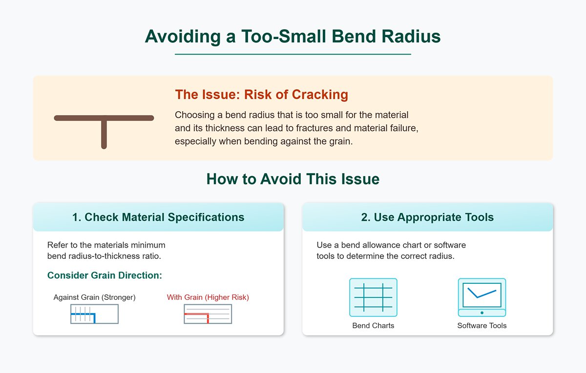
(1) Choosing a Bend Radius That’s Too Small
One frequent mistake in press brake operation is selecting a bend radius that is too small for the material. This can result in cracks, fractures, or permanent deformation, compromising the product’s structural integrity and appearance.
To avoid this issue:
1) Refer to the material’s minimum bend radius-to-thickness ratio, and consider grain direction—bending against the grain increases the risk of cracking.
2) Use a bend allowance chart or software tools (such as air bend force charts) to determine the appropriate bend radius.
(2) Placing Features Too Close to the Bend Line
Holes, slots, or grooves positioned too close to the bend line often distort during bending. This can weaken the material or render these features unusable.
To prevent this:
1) Place features at least three times the material thickness plus the bend radius away from the bend line.
2) If closer placement is necessary, enlarge the openings or redesign the part to minimize deformation.
(3) Improper Offset Spacing
Offsets or joggles placed too close together can cause tool interference or material distortion, complicating the bending process and driving up costs due to specialized tooling needs.
To avoid this:
Refer to standard offset spacing guidelines, and consult an engineer for customized solutions when necessary.
(4) Avoiding Narrow Flange Designs
Flanges that are too narrow can result in inaccurate bends, part deformation, and even tool damage. Narrow flanges also make it difficult to maintain consistent contact with the tooling during bending.
To reduce such risks:
1) Ensure the flange width is at least four times the sum of material thickness and bend radius.
2) If a shorter width is required, consider trimming the flange after bending.
(5) Ensuring Material-Tooling Compatibility
Using the wrong combination of material and tooling can lead to excessive press brake loading, inaccurate bends, or damaged tooling. For example, a punch tip radius that is too sharp for the material can cause cracks.
To prevent this:
Match the punch tip radius to the material thickness, and choose tooling appropriate for both the material type and the required bend geometry.
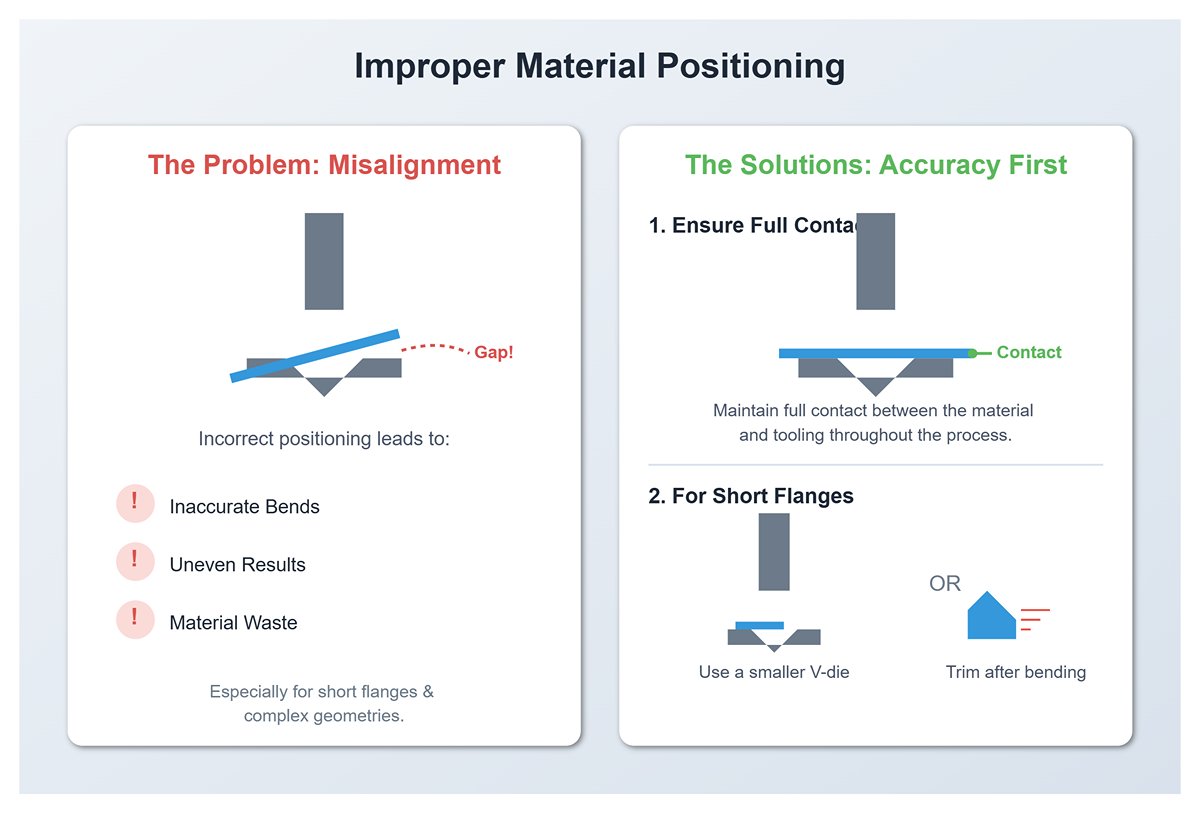
(6) Improper Material Positioning
Incorrect material positioning can cause inaccurate bends, uneven results, or material waste. This is particularly problematic for short flanges or complex geometries.
To ensure accuracy:
1) Maintain full contact between the material and tooling throughout the bending process.
2) Use a smaller V-die for short flanges, or trim after bending if necessary.
(7) Ignoring Springback Compensation
Springback—the tendency of material to partially return to its original shape post-bending—is often overlooked. This can lead to parts that fail to meet specifications.
To address this:
1) Understand the material’s elasticity and adjust the bend angle accordingly.
2) Use over-bending techniques or specialized tooling (such as hemming dies) to effectively counter springback.
7.2 Strategies for Bending Challenging Materials and Complex Shapes
Standard methods often fail when facing “tough customers”—extreme materials and highly complex geometries. In such cases, you need expert-level, customized strategies, as if performing precision surgery tailored to each unique challenge.
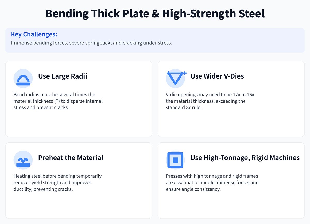
(1) Thick Plate and High-Strength Steel
The challenges with these materials include immense bending forces, severe springback, and a tendency to crack under stress.
1) Large radii are non-negotiable: Abandon the idea of using any radius smaller than the material thickness (T). Use a bend radius several times the thickness to disperse destructive internal stresses.
2) Wider V-dies are essential: Exceed the “8× rule” for V-die openings. For high-strength steels, V-die widths may need to be 12×–16× the material thickness to provide enough clearance and flexibility for deformation.
3) Preheating is the ‘sedative’: Heating certain steels to a few hundred degrees Celsius before bending can temporarily reduce yield strength, greatly improving ductility—like calming a wild beast—effectively preventing cracks.
4) High-tonnage, rigid machines are the backbone: Use presses with ample tonnage and high-rigidity frames (preferably with hydraulic deflection compensation) to handle immense forces and ensure consistent angles along the entire bend line.
(2) Thin Sheet and Precision Components
Here, the challenges are the opposite—avoiding even the slightest deformation or surface damage while achieving micron-level dimensional accuracy.
1) Surface protection is the ‘white glove’: Place a wear-resistant protective film between tooling and sheet, or use soft materials like polyurethane for the lower die. This prevents marks on aluminum, stainless mirror sheets, or painted panels—handling them as delicately as fine art.
2) Specialized small-radius tooling is the ‘embroidery needle’: Use finely ground small-radius punches and dies to accurately form tiny flanges.
3) Fine pressure control is the ‘breath’: Use high-precision servo-electric or hybrid presses capable of micron-level control over force and stroke, applying feather-light ‘breathing’ pressure to bend without damaging thin sheets.
(3) U-Shapes / Z-Shapes / Complex Profiles
The main challenges are cumulative errors in multiple bends, unpredictable springback, and interference between the workpiece and the machine itself.
1) Process sequence simulation determines success: Bend sequence is critical. Use professional offline programming software for 3D simulation—like planning chess moves—to preview the process, devising the optimal path that avoids collisions between the part and the machine.
2) Specialized tooling is the “key”: Complex Z-bends often require the use of a gooseneck punch to skillfully avoid interference with already formed flanges. Extra-deep U-bends may need to be completed in multiple stages or with the aid of exceptionally tall, custom-made dies.
3) Precise springback control is the heart of the process: In complex geometries, the springback from each bend introduces positioning errors for the next, potentially triggering a cascade of inaccuracies. Accurately measuring and compensating for the springback of the very first bend is the pivotal step that determines the success of the entire puzzle.
7.3 Industry Standards and Best Practices
The advancement of cutting-edge technologies relies on solid standards and shared industry consensus. These act as the “ballast” that keeps innovation on course.
While there is no single, globally mandated standard specifying exact bend radii, the following authoritative test method standards provide a scientific basis for defining the minimum bend radius of materials, serving as reliable technical references during the design phase to mitigate risk:
(1) ISO 7438:2020
Specifies the general method for bend testing of metallic materials, enabling a scientific evaluation of a material’s ability to withstand plastic deformation during bending without cracking.
(2) ASTM E290-14
A standard published by ASTM International for ductility bend tests of metallic materials, widely applied across North America and serving as a key reference for assessing formability.
(3) DIN 6935
A German standard specifically addressing cold bending of flat steel products, offering detailed guidance on recommended minimum bend radii for various steel grades and thicknesses. It has had a significant influence on European manufacturing.
Ⅷ. FAQs
1. How to manage springback in radius bending?
To manage springback in radius bending, understand that springback is the metal's tendency to return to its original shape. Mitigate this by calculating and compensating for springback using bend angle formulas and calculators to determine the necessary over-bending angle. Tooling adjustments, like using narrower die angles or specific punch designs, can help.
Process modifications such as air forming, adjusting binder pressure, and slowing down press speeds can reduce springback. Post-bending techniques like post-stretch operations and over-forming can correct deviations. These methods ensure precise bends and high-quality results in press brake operations.
2. What is the minimum bend radius for different sheet metal thicknesses?
Minimum inside bend radius for designing sheet metal parts depends on the material and thickness. For 1-6 mm thickness, it's usually equal to the thickness. You also use material thickness to determine the minimum number of upper punches.
For 6-12 mm, about 1.5 times the thickness. For 12-25 mm, 2 to 3 times the thickness. Aluminum needs 1 to 3 times, steel 0.8 to 2.5 times, and stainless steel 2 to 4 times the thickness. Bending method and die opening width affect these guidelines, with harder materials requiring larger radii due to springback.
Ⅸ. Conclusion
Bend radius plays a crucial role in sheet metal bending, and the correct inner radius ensures the bending quality of the workpiece. The inner radius can also be used to calculate key parameters such as bend allowance and bend deduction.
An improper natural inside radius can result in the deformation or even breakage of the workpiece. This article provides an overview of sheet metal bending. The use of the ADH press brake, whether a CNC press brake or an NC Press Brake, can help in producing more precise workpieces. If you have any questions about large radius bending or any other type of sheet metal bending on a press brake, please contact us for expert guidance.


