Despite the market dominance of hydraulic systems, the distinct types of mechanical press brakes remain the unassailable "hidden champions" of high-volume manufacturing, offering cycle times and bottom-dead-center rigidity that modern machines cannot match.
This guide dissects the engineering anatomy of these powerhouses—from flywheel-driven kinetic energy to critical clutch safety variations—providing the technical depth required to transform "outdated" iron into a strategic, high-margin production asset.
I. Strategic Insight: Why Mechanical Press Brakes Remain High‑Output “Hidden Champions”
Even in an era dominated by CNC hydraulic and fully servo‑electric press brakes, the mechanical press brake has not been pushed into extinction. Instead, it remains highly sought after in the second‑hand market and in high‑throughput workshops—far from merely being “cheap.”
Its enduring relevance comes from two physical advantages that hydraulic machines simply cannot match: kinetic energy storage and bottom‑dead‑center rigidity. For readers comparing machine categories, exploring the different types of press brakes offers helpful context.
For manufacturers chasing maximum cycle rates, a mechanical press brake is not a relic of the past—it is a physics‑driven solution precisely built for specific production bottlenecks. More insights on the mechanical architecture can be found in the detailed overview of press brake structure and components.
1.1 Reframing Core Value: The Physical Moats of Speed and Rigidity
Mechanical press brakes don’t operate through hydraulic force; they run on the flywheel effect combined with the sinusoidal mechanics of a crank‑link system. Understanding this foundation is essential to selecting the right machine.
- Instant Kinetic Energy Release (The Flywheel Effect): Unlike hydraulic machines, which must rebuild pressure every cycle, mechanical press brakes store energy in a constantly rotating flywheel. Once the operator steps on the pedal and the clutch engages, that stored energy is released into the ram with virtually zero delay. For companies researching cycle‑time improvements, reading about the full press braking process can support proper application decisions.
- Practical Impact: For short‑stroke bending cycles, mechanical machines typically achieve 1.5 to 2 times the throughput of hydraulic units of the same tonnage. For simple parts that don’t require long dwell times—such as electrical‑cabinet brackets or building clips—this translates into a direct doubling of output.
- Infinite Mechanical Advantage at Bottom Dead Center: Often overlooked by purchasing teams, this is a decisive factor. Because the crank‑link mechanism approaches a theoretically infinite mechanical advantage near BDC (180°), the machine delivers its maximum force right at the end of the stroke—limited only by material and frame elasticity.
- Engineering Significance: This makes mechanical machines exceptionally capable of coining and bottoming. Like a punch press, they can deliver a hard, precise hit at the bottom of the stroke, eliminating spring‑back through pure mechanical impact—no need for expensive scales or real‑time hydraulic compensation. For tailored recommendations, you may contact us for expert consultation.
1.2 Modern Manufacturing Positioning: Challenging the “Outdated Technology” Bias

Within a modern production layout, a mechanical press brake should not be treated as a general‑purpose bender. It should be recognized as a hybrid specialist bridging stamping and bending.
- Unmatched for Punching Operations: It’s an open industry secret: using a high‑end CNC hydraulic press brake for gang punching will quickly destroy valves and seals due to snap‑through shock (reverse tonnage).
- Why: When the punch breaks through the sheet, resistance collapses instantly, creating a hydraulic shock wave. The rigid mechanical linkage of a mechanical press brake absorbs this impact naturally, protecting the drivetrain. Smart plant managers keep mechanical machines for punching, embossing, and corner‑notching, sparing their precision hydraulic equipment from high‑impact abuse.
- Minimalist Maintenance: No hydraulic leaks, no temperature‑induced accuracy drift, and no complex servo valve systems. Maintenance revolves around managing mechanical wear—mainly brake and clutch pads—which is far cheaper and requires much less technical expertise. For small and mid‑sized factories without senior electrical engineers, this “plug‑and‑play reliability” is a major economic advantage. For specification sheets and model comparisons, check the available brochures.
II. Full Technical Taxonomy: A Deep Anatomy of Mechanical Press Brakes
If hydraulic press brakes are weightlifters relying on static pressure, mechanical press brakes are martial artists striking with rotational kinetic energy. To understand their true strengths—and choose the right model—we must look beyond the exterior and analyze their heart (drive system), muscles (frame), and brain (control logic). A broader perspective on product families can be seen on the ADH Machine Tool website.
2.1 Dimension One: Drive, Clutch, and Brake Systems (The Determinants of Productivity and Safety)

This is the most fundamental—and safety‑critical—classification. It dictates output characteristics, suitability for stamping vs. bending, and most importantly, whether you can legally install a safety light curtain.
A. Drive Transmission: How Energy Reaches the Ram
Mechanical press brakes draw power from the flywheel’s inertia—but how that inertia is used defines the machine’s personality.
Flywheel Direct‑Drive (Non‑Geared)
- Profile: The motor spins a large flywheel directly connected to the crankshaft (or via belts), with no reduction gearing.
- Performance: Very high speed, low torque. The ram moves with explosive velocity, relying heavily on flywheel RPM.
- Best For: Thin‑sheet punching, high‑speed blanking, and shallow bends.
- Selection Risk: The tonnage curve is steep. Attempting slow deep‑forming or thick‑plate bending will drain flywheel energy mid‑stroke, causing the notorious “stuck on bottom” incident—where the ram freezes just before BDC, often requiring torch cutting to free the tooling.
Geared Drive
- Profile: Flywheel energy is transferred through one or more reduction gear stages to amplify torque.
- Performance: Slower but far more powerful. It trades SPM for the ability to maintain rated tonnage over a longer stroke.
- Best For: The true bending workhorse—ideal for forming thick plate, coining, and jobs requiring longer sustained force.
B. Clutch Types: Are You Running a “Finger‑Breaker” or a Safe Machine?
A crucial detail for second‑hand buyers and EHS managers—one that directly determines safety compliance.
Mechanical Rigid Clutch (Mechanical Positive / Dog Clutch) (Hazard Level: ⭐⭐⭐⭐⭐)
- Operating principle: Power is transmitted through metal dogs or rolling keys that physically lock together. Once the pedal is pressed, the clutch engages in a hard lock, and the ram is forced to complete a full 360‑degree cycle before it can disengage.
- Regulatory red line: Light curtains must never be added. This isn’t a control-system issue—it’s physics. When an operator reaches into the danger zone and breaks the light curtain, the controller may command a stop, but the mechanically locked clutch cannot release. The machine simply cannot stop. This design is heavily restricted under US, EU, and Chinese standards and is only allowed when paired with full physical guarding or dual‑hand controls.
- Industry nickname: Commonly referred to as a “full‑revolution clutch” press.
Air / Hydraulic Friction Clutch (Modern Standard)
- Operating principle: Similar to an automotive braking system, pneumatic or hydraulic pressure clamps friction plates to transmit power; separation is achieved with spring braking.
- Key advantages: True inching and emergency stopping. Releasing the pedal or hitting the E‑Stop allows the ram to halt at virtually any point in the stroke within milliseconds.
- Regulatory position: This is the only clutch type legally compatible with light curtains. Known as a “part‑revolution clutch,” it’s the only acceptable choice for modern factories.
2.2 Dimension Two: Frame Architecture (Rigidity and Workpiece Capacity)
The violent impact forces generated at bottom dead center demand a frame strong enough to withstand them. Frame architecture directly determines both accuracy and long‑term structural stability.
C‑Frame / Gap Frame
- Structural traits: From the side, the frame resembles the letter “C,” offering an open throat.
- Advantages: Highly versatile, allowing the bending of sheet metal wider than the frame by utilizing throat depth.
- Inherent drawback: The “gator‑mouth effect” (yaw/deflection). Under high tonnage impact, the open C structure flexes outward, causing the center angle to hold true (90°) while both ends deviate (e.g., 88°).
- Mitigation: Older mechanical presses lack dynamic crowning systems. Skilled technicians must compensate manually through tedious shimming.
Straight Side / O‑Frame
- Structural traits: A closed, box‑type frame with the ram moving between two vertical columns.
- Status: The king of rigidity. This configuration minimizes angular distortion and provides exceptional vertical stiffness.
- Applications: Ideal for precision progressive tooling or ultra‑high‑tonnage forming. Though it limits workpiece width (to the space between columns), within that range it offers bottom‑dead‑center parallelism unmatched even by hydraulic presses.
2.3 Dimension Three: Control and Axes (Automation Potential)
Do not expect a mechanical machine to behave like a CNC hydraulic press. Its automation ceiling is fundamentally limited. Understanding what constitutes a “pseudo‑CNC” upgrade is crucial.
Fully Manual Axes
- Y‑axis (ram): Shut height is adjusted by rotating a large pitman‑arm adjustment nut—via crank or basic motorization. This cannot change automatically during a bend sequence, meaning each tooling setup can produce only one fixed angle.
- X‑axis (backgauge): Manually positioned with a handwheel, or even by marking lines.
NC Backgauge Retrofit
- Technical reality: This is the practical limit of upgrading a mechanical press. A servo‑controlled CNC backgauge can be added for automated X‑axis movement.
- Harsh truth: True CNC control of the Y‑axis is nearly impossible. Mechanical clutch response varies with temperature, wear, and inherent lag, preventing precise ram positioning required for air bending (e.g., stopping at exactly 135.02 mm).
- Conclusion: Mechanical presses are fundamentally bottoming/coining machines. Any retrofit claiming full CNC angle‑programming with variable Y‑axis control is typically unstable and inaccurate in real production.
Table 2‑1: Key Selection Matrix for Mechanical Press Brakes
| Key Feature | Mechanical Rigid Clutch (Full Rev) | Air Friction Clutch (Part Rev) | Modern Servo‑Hydraulic |
|---|---|---|---|
| Mid‑stroke stop ability | ❌ Impossible (extremely dangerous) | ✅ Yes (millisecond‑level) | ✅ Standard |
| Light curtain compatibility | ❌ Illegal/ineffective | ✅ Legal | ✅ Standard |
| Bending mode | Bottoming/coining only | Bottoming with limited air bending | Full capability (air + bottoming) |
| Y‑axis accuracy | Mechanical dead‑stop (high repeatability) | Mechanical dead‑stop (high repeatability) | Encoder‑based (high flexibility) |
| Maintenance focus | Pure mechanical wear (low cost) | Seals, friction plates (moderate) | Valves, seals, oil temperature (high) |
III. Engineering Physics: Critical Performance Parameters and the “Death Red Lines”
Mechanical and hydraulic press brakes differ at the most fundamental physical level. Hydraulic presses deliver near‑constant static force, while mechanical presses deliver force as a function of ram position. Misunderstanding this physics doesn’t just lead to poor purchasing—it can turn the machine into a latent hazard on your shop floor.
3.1 Tonnage Curve and the Bottom‑Dead‑Center Effect
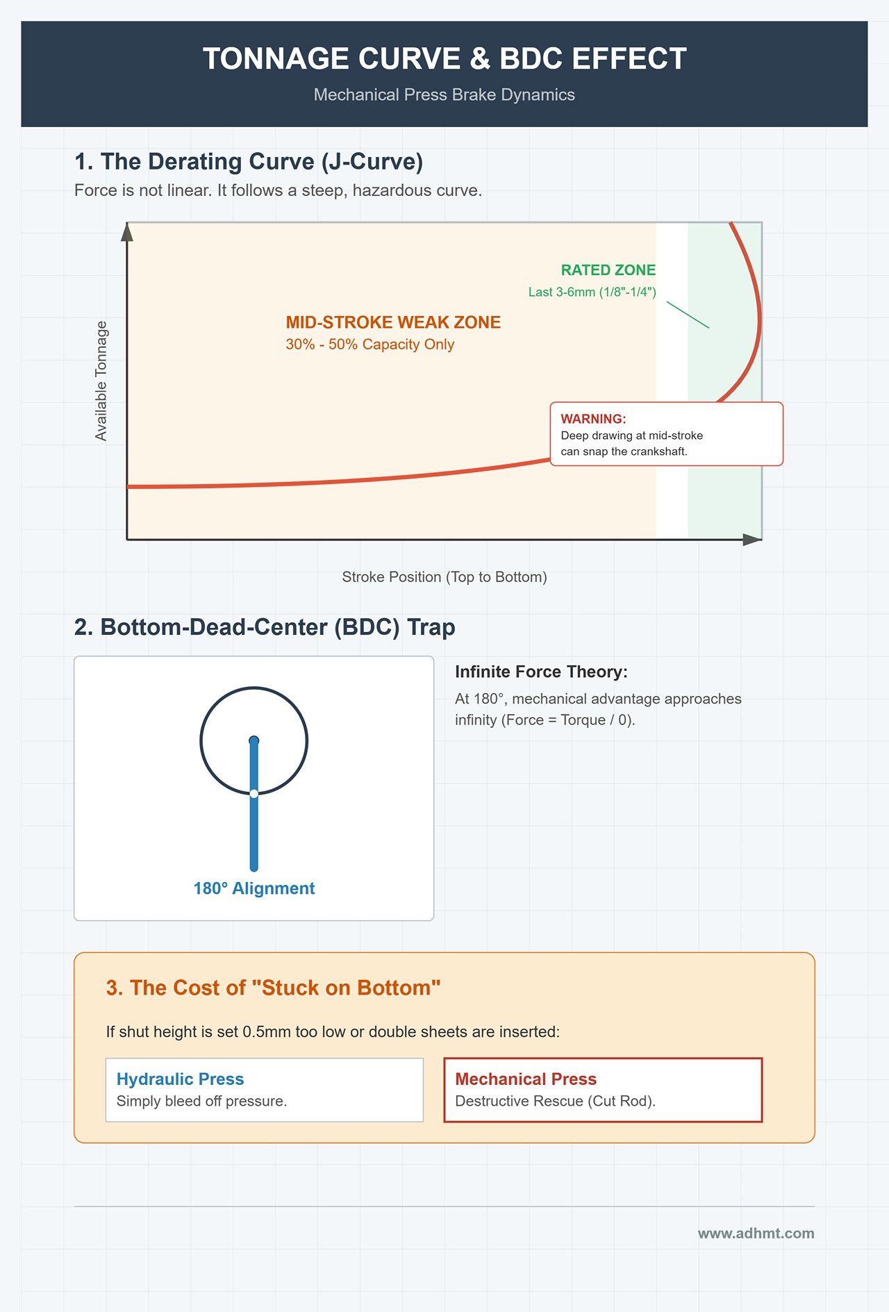
A mechanical press produces force along a steep, hazardous J‑shaped curve—not a straight line. Understanding this curve is the first and most essential step in selecting and using a mechanical press brake safely.
A. Derating Curve: The Overlooked Mid‑Stroke Weak Zone
Many novice buyers fall into a costly trap: they assume that a 100‑ton mechanical press brake can deliver its full 100 tons of force at any point in the stroke. This misconception can be extraordinarily expensive.
- Physical Reality: A mechanical press brake’s rated tonnage is valid only under very narrow conditions—specifically within roughly 3 to 6 mm (1/8"–1/4") above bottom dead center (BDC).
- Mid‑Stroke Weakness: In the middle of the stroke, the crank-and-connecting‑rod geometry becomes highly unfavorable, pushing the mechanical advantage to its lowest point. Even though the flywheel still stores ample kinetic energy, only about 30%–50% of the rated tonnage can be converted into vertical forming force.
- Practical Warning: Attempting deep drawing or high‑position punching at mid‑stroke—even if your tonnage calculations show only 60% of rated load—can easily overtax the machine, causing motor stalls, flywheel energy collapse, or even a snapped crankshaft.
B. The Bottom-Dead-Center Power Trap
When the crank reaches 180 degrees and the connecting rod aligns perfectly straight with the crankshaft at bottom dead center, the mechanical advantage theoretically approaches infinity (Force = Torque / 0).
- The Temptation of “Infinite Force”: At this singular position, a mechanical press brake can exceed its structural design limits. This is precisely why it excels at coining—it can deliver massive pressure at the stroke’s end, locking metal grains into shape.
- The Red Line (Stuck on Bottom): This is also the machine’s Achilles’ heel. If the shut height is set even 0.5 mm too low—or if the operator inadvertently inserts two sheets—the ram will reach BDC with no ability to release energy, trapping hundreds or even thousands of tons of force inside the frame.
- The Cost of Rescue: This “locked bottom” or “jammed” condition is infamous. Unlike a hydraulic press, which can simply bleed off pressure, a mechanical press jammed at BDC often requires destructive rescue methods—typically cutting the expensive connecting rod with a torch or using specialized hydraulic nut breakers.
3.2 Speed Characteristics and Dynamic Accuracy
Another defining trait of mechanical presses is their intense speed. If a hydraulic press moves with steady, programmable control, then a mechanical press behaves like a wild horse driven by a sinusoidal motion pattern.
A. Sine-Wave Velocity Profile
A mechanical press brake’s ram speed is never constant; it strictly follows the sinusoidal motion dictated by crank rotation.
- Dangerous Mid‑Stroke Speed: At the mid‑points of the stroke (90° and 270°), the ram reaches peak velocity. When bending wide sheets here, the free edge can whip upward with extreme angular speed. This “whip‑up effect” can strike an operator’s chin or chest with severe force.
- Natural Slowdown Near BDC: As the ram nears bottom dead center, its speed naturally drops to zero. This helps metal flow during forming but eliminates any possibility of programmable bend‑speed control—unlike servo-hydraulic machines. You must work to the machine’s rhythm, not the other way around.
B. Dynamic Accuracy and Stop Time
This is the key physical criterion that determines whether an old mechanical press can be legally retrofitted for modern safety compliance.
- Brake Uncertainty: Mechanical presses rely on friction brakes. As pads wear, air pressure fluctuates, or contaminants enter the system, the stopping time (T_s) gradually increases.
- The Safety Distance Red Line: International standards (OSHA, ISO 13855) require that light‑curtain safety distance D_s be calculated as D_s = K × (T_s + T_c) + D_pf. On older machines, T_s can degrade from 100 ms at the factory to more than 300 ms, forcing the light curtain to be placed half a meter or more from the tooling to remain compliant.
- Recommendation: If your machine’s stopping time is unstable, never retrofit it with a light curtain. It gives operators a false sense of safety because the machine simply cannot stop in time. Such presses should only be used with full enclosures or dual‑hand control stations.
IV. Selection in Practice: Decision Matrix and TCO Evaluation
Beyond physics and nostalgia, equipment purchasing is ultimately a battle for capital efficiency. When choosing between mechanical, hydraulic, and all‑electric servo press brakes, the question is not “Which technology is the most advanced?” but “Which machine produces your parts at the lowest cost per piece?” This chapter provides a clear, unsentimental framework to help you avoid costly mistakes.
4.1 The "Go/No-Go" Selection Decision Tree
A mechanical press brake is not a universal solution. In today’s high‑mix, low‑volume manufacturing environment, it often becomes a misfit. Yet in certain high‑throughput scenarios, it is an unmatched money machine. Use this three‑stage decision funnel; a single “No” means you should switch to a modern CNC hydraulic or servo press brake.

- Filter 1: Is Your Order Portfolio Dominated by High‑Volume Single Items?
- Scenario: You typically produce batches of over 5,000 pieces of simple components (bridge‑tray brackets, cabinet connectors, building fasteners), and once the tooling is set, you may run for three days or even a week without a changeover.
- Criteria:
- Yes → Pass. The mechanical press brake’s high stroke rate (40–100 SPM) yields enormous throughput.
- No → Stop. If you change tooling more than three times a day, the mechanical press’s manual setup process (30–60 minutes) will erase all speed benefits. Choose a CNC hydraulic press with automatic crowning.
- Filter 2: Does Your Process Depend on High‑Impact Forming?
- Scenario: Your parts require coining for ultra‑tight radii, or involve gang punching, embossing ribs, or shear‑cutting—operations with high impact loads.
- Criteria:
- Yes → Pass. The mechanical press brake’s infinite stiffness and explosive energy release at BDC make it ideal for such operations.
- No → Terminate. If your main workflow relies on precision air bending and you need to hold angle tolerances within ±0.5° while dealing with fluctuating material thickness across batches, a mechanical press brake is the wrong tool. It cannot dynamically adjust slide position to compensate for springback, and the resulting scrap rate will be unbearable.
- Filter 3: Do You Have True “Master‑level” Talent on Your Team?
- Scenario: Do you have technicians with 10+ years of hands‑on experience—people who can diagnose a machine by sound and fine‑tune die alignment by shimming purely through feel?
- Criteria:
- Yes → Pass. Skilled operators are the true source of accuracy on a mechanical press brake.
- No → Terminate. A mechanical machine has no “undo” button. A single misjudgment—such as feeding double‑stacked material—can lock the ram at bottom dead center or even fracture the frame. If you rely heavily on junior operators, buy a modern machine with error‑proofing and graphical programming instead.
4.2 Die Compatibility and System Matching
A major hidden trap in machine selection is mismatched die systems. Many buyers attempt to mount high‑precision European‑style (Promecam) tooling onto old mechanical machines using adapters. This is like putting a Ferrari gearbox on a tractor—completely incompatible and potentially destructive.
- American Planed Tooling: rugged, forgiving, and battle‑tested
- Compatibility: Most mechanical press brakes are built around American‑style die interfaces.
- Survival logic: These dies are usually machined from solid steel blocks. Their accuracy is modest, but they are extremely durable. They can withstand the violent impact forces a mechanical machine releases at bottom dead center without cracking. For bottoming operations requiring hundreds of tons of pressure, American tooling is the only economical—and safe—choice.
- Cost advantage: The used‑tooling market is huge, and worn dies can be resurfaced with simple planing.
- The “culture shock” and fracture risks of European tooling
- Fatal mismatch: European tooling is typically surface‑hardened (e.g., laser‑hardened), reaching 50–60 HRC. This gives high hardness but also brittleness. Mechanical brakes lack the soft‑touch cushioning of hydraulic systems, so their rigid impacts can easily chip the die edges or even cause catastrophic die explosions that endanger operators.
- The precision paradox: European tooling is designed for CNC micro‑adjustments. On a mechanical brake with only manual adjustments, ±0.01 mm precision tooling provides no real accuracy benefit—only unnecessary expense.
4.3 Total Cost of Ownership (TCO) Calculation Model
Don't be misled by the low upfront price of used mechanical press brakes—often just one‑fifth the cost of a new hydraulic machine. Over a five‑year lifecycle, the structure of your total cost of ownership (TCO) shifts dramatically. Below is a breakdown of key cost drivers for a typical production environment:
| Cost Dimension | Mechanical Press Brake | CNC Hydraulic Press Brake | Servo‑Electric |
|---|---|---|---|
| Initial Capital Expenditure (CapEx) | Very low ($10k–$30k) | Medium ($50k–$150k) | High ($100k+) |
| Energy Efficiency | Low (flywheel runs continuously; extremely high idle consumption) | Medium (power only during the downstroke; idle pump losses) | Very high (power on demand; zero idle energy) |
| Maintenance Characteristics | Pure mechanical upkeep (frequent replacement of brake pads and clutch plates; low skill threshold but high frequency) | Hydraulic system maintenance (oil changes, valve cleaning, seal aging; high cost) | Minimal maintenance (ballscrew lubrication; nearly maintenance‑free) |
| Setup & Scrap | High (first‑piece setup is difficult; long tool‑change time; high initial scrap rate) | Medium (CNC assistance enables high first‑piece pass rate) | Low (fully closed‑loop control; extremely low scrap rate) |
| TCO Advantage Point | Continuous full‑load production | Multi‑variety, mixed production | High‑precision, clean production |
- Financial insight: If your equipment utilization (OEE) is below 40%—meaning the machine spends most of its time idling or in tool‑change—then the flywheel’s massive idle energy consumption becomes a financial drain. Conversely, in 24/7 high‑speed stamping or bending applications, a mechanical press brake’s low maintenance costs and exceptional throughput make it a TCO‑optimized cash generator.
V. Operations and Safety: A Practical Guide for Operators and Engineers
A mechanical press brake is not a cold, predictable machine—it is a kinetic beast with explosive energy. Unlike modern hydraulic machines that rely on electronic sensors, mechanical‑press operation depends on acute awareness of physical signals such as sound, vibration, and temperature.
For workshop managers, building an operations and maintenance system based on these physical indicators is the only way to balance productivity and safety.
5.1 Golden SOP: The Art of Dancing With Stored Energy

Mechanical machines offer almost no margin for error. Once the flywheel passes the clutch engagement point, the stroke is irreversible. Therefore, the heart of any SOP must shift from “correcting mistakes afterward” to “detecting danger beforehand.”
A. The Pre‑Start ‘Three‑Listen, Three‑Check’ Ritual: Seasoned technicians never start feeding material right after power‑up. They first perform a strict sensory check.
- Listen to the flywheel idle (Heartbeat Check): After starting the main motor, do not press the pedal. A healthy flywheel produces a deep, even hum.
- Warning sign: Rhythmic clicking or sharp metallic whines typically indicate dry flywheel bearings or worn keyways. Stop immediately—at high RPM, a flywheel can detach with lethal force.
- Listen to clutch engagement: Perform a single‑stroke air cycle. The sound should be a crisp, short “click–thump.”
- Warning sign: A prolonged hissing noise or delayed metal impact indicates worn friction pads or insufficient air pressure. This means stopping distance is no longer within the safe range and the light curtain may not stop the machine in time.
- Check ram return to top stop: Verify that the ram stops precisely at top dead center.
- Warning sign: If the ram shows noticeable overshoot or drift, the brake torque has weakened. This is one of the most dangerous symptoms—adjust brake spring pressure immediately.
B. Worst-Case Scenario: Jammed at Bottom Dead Center (Stuck on Bottom) This is a disaster unique to mechanical presses. If the die shut height is lowered by even 0.5 mm, or an operator accidentally feeds two sheets stacked together, the massive kinetic energy stored in the flywheel can drive the ram firmly “welded” into bottom dead center.
- Strictly Forbidden: Many beginners repeatedly tap the “motor reverse” button in panic. This does nothing—the flywheel cannot gain speed—and will instead burn out the main motor windings almost instantly.
- Expert-Level Recovery Methods:
- Mechanical Release Method: Position a high‑capacity hydraulic porta-power jack between the ram and lower bed to push the ram upward and relieve tension in the connecting links.
- Thermal Expansion–Contraction Method: A classic old‑school technique. Apply heat to the tie rods while cooling the load-bearing points of the tooling with dry ice. The resulting micro‑scale expansion and contraction helps free the jam when combined with manual flywheel rotation.
- Last Resort: If all else fails, use an oxy‑acetylene torch to cut the tie‑rod bolts. Sacrifice the consumable parts to protect the main machine structure.
5.2 Fault Diagnosis and Preventive Maintenance: Stethoscope and Grease
Mechanical press failures are typically the result of gradual physical wear, not sudden electronic faults. Effective maintenance revolves around a preventive system built around lubrication and clearance control.
Table 5-1: Typical Mechanical Press Brake Fault Diagnosis Matrix
| Symptom | Root Cause | Diagnosis & Action |
|---|---|---|
| Black oil thrown from flywheel side | Bearing overheating causing grease carbonization | Red alert: This is a precursor to bearing seizure. Disassemble the flywheel immediately, clean oil passages, and replace with high‑temperature grease (recommended NLGI #2 lithium). |
| Uneven bend angle across ends | Pitman screw joint wear or worm‑gear lock failure | Precision check: Use a dial indicator to measure left‑right BDC height difference. If deviation returns quickly after adjustment, inspect whether the bronze bushing has worn into an oval. |
| Slow response when pressing the pedal | Rotary union air leak or clogged solenoid valve | Acoustic check: Listen near the flywheel center for leaking air. Replacing rotary‑union seals (about $50) often resolves major issues at minimal cost. |
| Excessive brake dust | Asynchronous brake release (Brake drag) | Clearance adjustment: Check pneumatic timing to ensure clutch engagement and brake release occur simultaneously, preventing overheating and wear. |
Maintenance Rule of Steel: Stop Time Measurement (STM) This is the non‑negotiable safety baseline. Every quarter, use certified instruments to measure the ram’s stopping time—from emergency-stop activation to full stop—in milliseconds.
- If STM exceeds the original value by 10–15% (for example, rising from 150 ms to 170 ms), brake pads must be replaced immediately or the safety light curtain repositioned (safe distance = stop time × hand movement speed). Ignoring this metric is equivalent to leaving the operator unprotected.
5.3 Modernization Roadmap: Rational Investment Logic

Mechanical press‑brake retrofits should follow the principle of leveraging strengths and avoiding weaknesses. Don’t try to defy physics by turning it into an all‑in‑one machine—enhance its role as a high‑efficiency forming tool.
A. High‑ROI Smart Investments
- NC Backgauge System: The highest value‑for‑money upgrade. Mechanical presses cycle extremely fast, and the true bottleneck is often manual positioning. Adding a servo‑driven X‑axis backgauge helps the operator keep pace, boosting overall throughput by more than 50%.
- Brake Monitor & Dual Solenoid Valve: Mandatory under modern safety standards. A brake monitor checks each stop distance in real time and locks the machine immediately if brake performance declines, preventing dangerous repeat‑stroke incidents.
B. Retrofits to Avoid—Expensive Traps
- Attempting Y‑axis CNC Angle Programming: Any claim that a mechanical press can behave like a hydraulic press—adjusting depth automatically by angle input—is fundamentally unreliable. The BDC is determined by crank geometry. Although motorized link‑length adjustment exists, it is slow and heavily affected by thermal expansion. You usually end up with an overpriced digital display, not true CNC control.
- Installing Light Curtains on Full‑Revolution Clutch Machines: If your machine uses a dog clutch/full‑revolution clutch, light curtains are strictly prohibited. Once engaged, this clutch cannot disengage mid‑stroke—the machine will continue to descend even if the curtain is triggered. The only compliant upgrades are full enclosure guarding or anti‑tiedown two‑hand control stations.
VI. Future Outlook: The Evolution of Mechanical Press Brakes
In the era of Industry 4.0 and digital transformation, opinions on the fate of mechanical press brakes diverge sharply. Some view them as doomed industrial dinosaurs; others argue their physical characteristics offer irreplaceable advantages.
Reality shows they are not disappearing—they are quietly undergoing species‑level evolution. The mechanical press brake of the future will be a fusion of physical rigidity and digital intelligence, no longer just a flywheel‑and‑clutch machine.
6.1 Servo‑Mechanical Hybrid Drives: The End of the Clutch Era

The biggest drawbacks of traditional mechanical brakes are their fixed ram speed and the maintenance burden caused by clutch wear. The next major evolutionary step is servo‑crank technology.
- Technical Principle: Completely eliminate high‑energy flywheels and wear‑prone friction clutches. A high‑torque servo motor drives the crankshaft directly through a reduction system.
- Evolutionary Advantages:
- Preserved Mechanical Rigidity: Retains the crank mechanism’s immense force multiplication at BDC and its excellent impact resistance—still unmatched for coining operations.
- New Digital Flexibility: Introduces variable‑speed capability never before possible in mechanical presses. The ram can descend rapidly before contacting the sheet, slow automatically upon contact to prevent whip‑up, and return at full speed.
- Energy revolution: During standby, the motor remains completely still—drawing zero power—and only delivers output during the actual bending stroke. This results in a 40%–60% energy savings compared with traditional flywheel-driven machines.
This hybrid architecture represents the ultimate evolution of mechanical press brakes: it combines the controllability of hydraulic systems with the speed and rigidity that define mechanical machines.
6.2 The awakening of “silent machines”: IoT empowerment for legacy equipment
For the tens of thousands of aging mechanical press brakes still running in factories worldwide, the future is not scrappage but digital rebirth. Their simple structure and highly characteristic vibration signatures make them ideal candidates for predictive maintenance.
- Vibration fingerprint monitoring: Low-cost wireless accelerometers installed on the flywheel bearings and connecting rods capture the vibration spectrum during operation. AI algorithms can easily detect abnormal frequencies caused by bearing pitting or rod looseness, issuing alerts up to two weeks before a failure occurs.
- Real-time OEE linkage: By adding a simple counting sensor module, a “mute machine” built in the 1980s can be connected to the factory’s MES system. Managers gain real-time visibility into actual cycle rates, downtime, and output, turning a former black box into transparent operations.
6.3 Final verdict: from general-purpose to specialty-focused
The future landscape for mechanical press brakes will become sharply polarized. They will gradually withdraw from general-purpose sheet‑metal work—a domain now dominated by CNC hydraulic and all‑electric machines. Yet in select high‑value applications, they will reinforce their position as the undisputed choice.
The future selection map will look like this:
- High‑frequency, single‑part mass production (e.g., automotive brackets, appliance clips): Keep mechanical machines. Nothing matches their durability or low TCO at 60 SPM.
- High‑strength, high‑impact hard‑alloy processing (e.g., titanium alloys for aerospace, high‑strength steel punching): Rely on mechanical machines. They are the only systems capable of withstanding hundreds of tons of reverse impact without leaks or loss of accuracy.
- Multi‑variety, high‑precision prototyping: Phase out mechanical machines.
Summary: Mechanical press brakes themselves are not obsolete—what is outdated is the mindset of using them for everything. In the smart factories of the future, mechanical press brakes will serve as specialized tactical equipment, working alongside high‑precision hydraulic and electric machines to form a robust and efficient manufacturing ecosystem.


