Mastering types of press brake drawings files bridges CAD perfection and crash-free production—from DXF layer pitfalls to STEP simulations and controller-native formats. This guide reveals why flawless geometry still fails, delivering zero-defect workflows, troubleshooting trees, and SOPs for seamless factory integration.
I. Core Insight: Breaking the Misconception that “Geometry Equals Manufacturing”
Many seasoned engineers and shop supervisors have fallen into the same trap: assuming that as long as the flat‑pattern dimensions look correct in SolidWorks or AutoCAD, the finished part will be flawless. In sheet‑metal fabrication, this is one of the costliest myths you can believe.
Between the digital model on your screen and the physical machinery on the shop floor lies a gap that’s easy to overlook but costly to ignore. Unless you understand how file formats convey information between CAD and the machine, even the most advanced CNC press brake can end up producing scrap.
1.1 The Manufacturing Gap: Why Do Correct Designs Still Cause Crashes?
When we import a CAD file into a press brake controller, we’re essentially performing a complex act of translation. Any loss or misinterpretation during this process becomes the root cause of collisions, dimensional inaccuracies, and other costly errors.
The “parallel‑universe effect” of the K‑factor: Design engineers often rely on generic K‑factor presets in their software, such as 0.44 or 0.5. But the shop floor operates under real‑world physics. The V‑die opening typically follows the “eight‑times‑material‑thickness” rule, and the resulting actual Bend Deduction (BD) can deviate from the theoretical design value by 0.5 mm—or even 1 mm. On a precision part with four or five sequential bends, that accumulated error is enough to throw critical hole positions completely off. A DXF file carries only geometric lines, while stripping away the material‑deformation logic that truly matters.
The Phantom Collision: This is the most serious hazard created by a 2D mindset. A DXF file is fundamentally flat—it has no sense of thickness or height. When the controller reads a DXF, it has no way of knowing how high a part will rise during bending, nor can it predict whether a flange will swing into the backgauge fingers as it springs back. This “blind spot from an otherwise godlike top-down view” is a leading cause of first‑piece scrap, damaged tooling, and even machine downtime.
1.2 The “Hybrid File Flow” Strategy: Combining 2D and 3D for Maximum Efficiency
To bridge this gap, leading modern manufacturing plants have moved beyond the old mindset of relying solely on a single DXF file. Instead, they now adopt a dual‑track Hybrid Workflow, built on a simple principle: use each file format for what it does best.
File type flow
Gold-standard format
Primary purpose
Manufacturing-side “reading comprehension”
2D Laser/Punch
DXF(AutoCAD 2000/2004)
Contour Generation and Path Planning
The machine reads geometry only. ⚠️ Critical note: bend centerlines must be fully removed—otherwise the laser interprets them as cut paths, leading to scrapped parts.
3D Press Brake
STEP(AP214/AP242)
Simulation Modeling and Automated Programming
The controller interprets full solid bodies and topology. ✅ Advantage: Delem or NexT systems automatically detect material thickness, match tools, and simulate bend sequences in 3D to reveal collision risks in advance.
Expert Insight: If your controller supports 3D file imports (such as the Delem DA‑66T and above or the Amada AMNC 3i), relying solely on DXF programming means you’re using barely half of your machine’s actual capabilities.
1.3 Core Value Commitment
This guide is far more than a simple file‑format specification. It is a fully field‑tested productivity optimization system. By following the standardized workflows outlined in the chapters ahead, your factory will achieve tangible, measurable improvements.
Zero trial‑run cost: By using STEP files correctly for either offline or online simulation, you can resolve all potential collision issues within a digital twin environment before a single sheet of material is cut.
Right First Time: By standardizing DXF files through disciplined layer management, you eliminate ambiguities in line attributes that can lead to laser miscuts or incorrect dimension interpretation, ensuring the very first part comes out exactly as intended.
Seamless Process Handoff: Establish a shared “universal language” between the design office and the workshop to eliminate unnecessary back‑and‑forth and minimize time lost to repeated clarifications and drawing revisions.
Next, we’ll take a deep dive into the inner architecture of these file formats and show you how to handle each one with the precision of a seasoned surgeon.
II. Format Decoding: A Deep Dive into File Types Commonly Used in Press Brake Operations
A file format is far more than the suffix at the end of a filename; it is the sole bridge linking digital design intent with the machine code that drives physical production.
In sheet‑metal manufacturing, choosing the wrong format is like sending a love letter written in Chinese to an engineer who speaks only German—every detail may be there, but the recipient won’t understand a thing. For beginners trying to understand machine communication, exploring topics such as press brake structure and components can provide a foundational perspective.
To truly master bending operations, you need a clear understanding of three essential file types: the industry’s universal currency, the 2D DXF; the backbone of smart manufacturing, the 3D STEP; and the controller‑specific “black box” formats that operate behind the scenes. For those evaluating technology choices, understanding the different types of press brakes is an excellent complementary step.
2.1 The Reigning Champion of 2D Vectors: Survival Rules for DXF Files
DXF (Drawing Exchange Format) reigns supreme in sheet‑metal fabrication. Nearly all laser cutters, punch presses, and entry‑level press brakes rely on it as their universal language. Yet handing a design‑grade DXF directly to a press brake often becomes the starting point of a production mishap. Engineers often revisit similar issues when learning how to read press brake blueprints, which strengthens interpretation accuracy.
Survival Rule 1: Radical Minimalist Cleanup (The Clean Room Policy)
Many engineers are used to leaving title blocks, frames, dimension notes, and even technical requirements inside the DXF file. For a CNC controller, this is a complete nightmare. It treats every text box as a geometric entity and tries to generate a machining path for it.
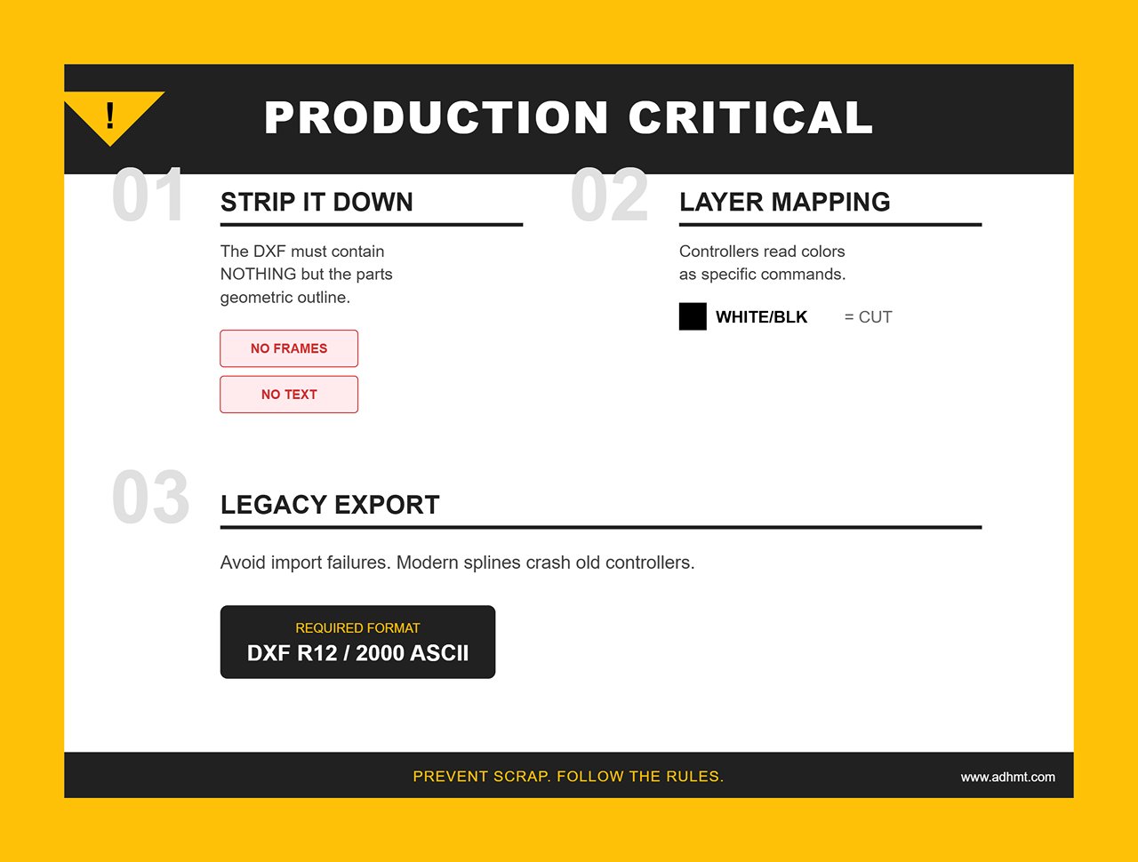
Iron Rule: The DXF file used for production must be completely stripped down. It should contain nothing but the part’s geometric outline. Any lines, notes, centerlines, or other elements unrelated to machining must be removed without exception.
If you need technical guidance or sample references, you may browse the free brochures provided by ADH.
Survival Rule 2: Layers Function as Commands (Layer Protocol).
High‑end controllers such as Delem or Cybelec don’t rely on line types like dashed or solid lines to determine bending direction. Instead, they interpret layer color or layer names as the definitive instructions for how a bend should be executed.
Standardization recommendation:
Layer 0 (white/black): Represents the outer contour of the part, which serves as the cutting line.
Layer BEND_UP (red): Indicates a front‑side bend line, also known as a mountain fold.
Layer BEND_DOWN (yellow): Indicates a reverse bend line (valley fold).
Layer MARK (blue): Used for etching or marking lines.
Mixing up layers can cause the controller to mistake bend lines for cut paths, or reverse the intended bend direction, resulting in immediate part scrap.
Survival Rule 3: The Version Trap
AutoCAD may be on its 2024 release, but most CNC controllers are still running technology from the early 2000s.
Avoiding the Pitfall: Always export DXF files as R12 or 2000 ASCII. Newer DXF versions introduce splines that many controllers cannot translate into arcs or lines, often causing import failures or sluggish machine performance.
2.2 The Foundation of Smart Manufacturing: STEP and 3D Formats
Once a factory adopts high‑end press brakes with 6‑axis backgauges or offline programming tools such as AutoPOL or Radbend, the limits of 2D DXF immediately surface. A DXF has no thickness and no volume. In these environments, the STEP (.stp/.step) format becomes the only reliable carrier of truth.
Why STEP Represents the Future of Bending DXF is a sheet of paper; STEP is a solid body. When a controller reads a STEP file, it doesn’t just see lines—it interprets the full topology.
Automatic Tool Matching: The system detects material thickness and recommends the correct V‑opening.
Collision Detection: This is STEP’s irreplaceable advantage. The controller can simulate the entire bend cycle, checking whether the part will collide with the punch, die, or backgauge during rotation—something no 2D DXF can achieve.
Key Distinction: AP203 vs. AP214 Choosing the correct STEP protocol is not a trivial decision.
AP203 (Configuration‑Controlled 3D Design): Contains geometry only.
AP214 (Automotive Mechanical Design Core Data): The recommended standard. It preserves colors and hierarchical information in addition to geometry.
Practical Value: If a designer marks a surface red to indicate a cosmetic face that must not be scratched, AP214 transmits that information to offline software, which will automatically avoid placing clamps or high‑friction operations on that surface.
2.3 Controller-Specific “Black‑Box” Formats
This is the part most operators and process engineers find to be the real “deep water.” DXF and STEP are universal exchange formats, but to make a machine actually move, these files must eventually be compiled into proprietary machine code that each controller brand can understand.
Gaining a grasp of these formats helps you break through the ecosystem silos that exist between different equipment manufacturers. Below is a comparison of the major control‑system “dialects”:
Control System Brand
Core File Suffix
Features and Generation Logic
Delem (DA Series)
.P (Product) / .DL
Native to Delem systems, typically generated by Profile‑T offline software. Beyond geometry, it packages sequences, tooling selection, and axis movements.
Amada (AMNC)
.BMF / .Ldd
A closed, tightly controlled Amada format, usually produced by Dr. ABE_Bend or VPSS 3i. It is a highly encrypted database containing extremely precise machine‑motion directives with very limited cross‑compatibility.
Cybelec
.CYB / .S
Used for ModEva and CybTouch systems and converted via PC1200 or VisiTouch. It offers a very compact description of 2D profiles.
Trumpf
.GEO / .LST
Generated by TruTops software. .GEO stores geometry, while .LST holds the processing list. These files are deeply intertwined with machine‑specific parameters.
Practical insight: Do not attempt to manually create or modify these “black‑box” files. A proper mixed‑format workflow should look like this: the design team outputs standardized STEP AP214 files, and process engineers (CAM specialists) use dedicated offline programming tools to convert those generic STEP files into the required .P or .BMF machine files with a single click.
Trying to bypass this compilation step and sketch shapes directly on the controller screen is one of the least efficient practices in modern precision manufacturing.
III. The Gold Standard: Practical Rules for Zero‑Defect DXF Files
In CNC bending, a perfect DXF is more than a drawing—it's a precise digital command. To the machine, a file full of redundant lines or undefined attributes is noise. Ensuring a clean signal from design to manufacturing requires file‑handling standards as rigorous as surgical procedure.
3.1 The Clean‑Up Checklist
Before exporting, the CAD file must undergo a strict “sterilization” process. Any non‑manufacturing element can be misread as a cut path or motion command, causing nozzle damage or calculation errors.
A. Elements That Must Be Removed
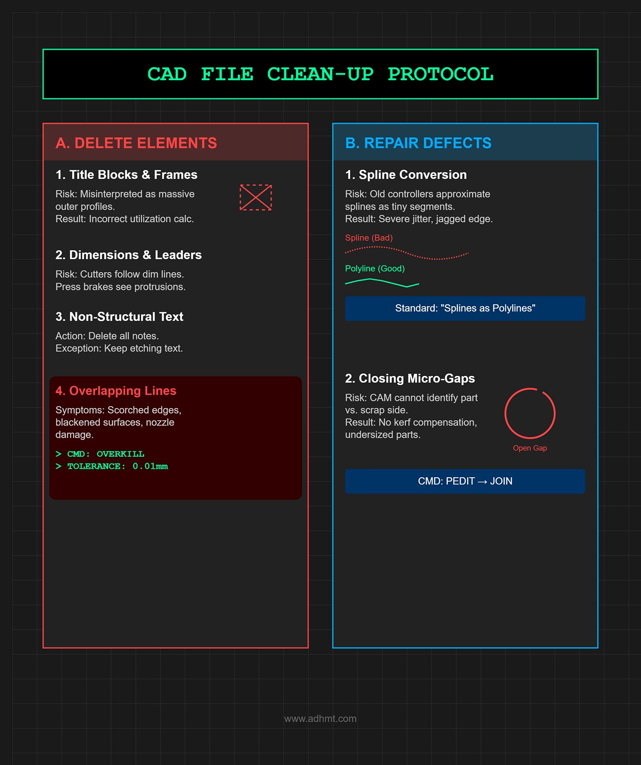
Title blocks and frames: Delete them completely. Controllers can misinterpret frames as massive outer profiles, leading to incorrect sheet‑utilization calculations.
Dimensions and leaders: Remove all. Laser cutters may attempt to cut along dimension lines, and press‑brake controllers may treat them as strange protrusions.
Non‑structural text: Delete all annotations except etching text. Machines cannot interpret notes—they will simply try to cut the characters.
Overlapping lines: One of the most insidious problems.
Symptoms: The laser makes repeated passes over the same point, scorching edges, blackening surfaces, and potentially destroying the nozzle.
Fix: Use AutoCAD’s OVERKILL command with 0.01 mm tolerance to merge overlapping geometry.
B. Micro‑Defects That Must Be Repaired
Spline Conversion:
Risk: Older controllers cannot process spline math. They approximate splines with hundreds of tiny line segments, causing severe jitter during cutting and producing jagged edges.
Standard: All splines must be converted into polylines. In SolidWorks or Inventor export settings, always enable the option "Splines as Polylines."
Closing micro‑gaps:
Risk: If the profile isn’t fully closed, CAM software cannot determine which side is the part and which is scrap. As a result, kerf compensation cannot be applied, and the finished part will be undersized.
Standard: Use the PEDIT → Join command to ensure every cutting loop is completely closed.
3.2 Intelligent Layer Mapping Strategy
The real difference between high‑end manufacturing and basic workshops lies in whether process intent is embedded through layers.
Never rely on linetypes such as dashed lines to indicate bend lines—these often disappear during file conversion. The only reliable method is to establish a standardized, color‑based layer mapping system.
Recommended standard (solidify this as an internal SOP):
Geometry Types
Layer Name
AutoCAD Color Index
Machine behavior instructions
Outer contour
CUT_EXT
White (7) / Green (3)
Laser through-cut
Inner bore
CUT_INT
White (7)
Laser through-cut (prioritize removal)
Front bend
BEND_UP
Red (1)
Generate forward bend step (mountain bend)
Back bend
BEND_DOWN
Cyan (4)
Generate flip-over bend step (valley bend)
Etching/Marking
SCRIBE / MARK
Yellow (2)
Low-power surface scoring (does not cut through)
Centerline
CONSTRUCTION
Gray (8)
Ignore (controller does not read)
Practical tip: In SolidWorks, under File > Save As > DXF > Options, enable “Custom map SolidWorks to DXF/DWG” and save the rules as a .map file. Distribute it to all design engineers to ensure uniform output across the entire plant.
3.3 Embedding Key Parameters: Units, Coordinates, and the K‑Factor
A DXF file is essentially mute—it contains geometry but lacks physical attributes. To make this “silent” file speak, we must use metadata and structured filenames.
A. Let the filename carry process information
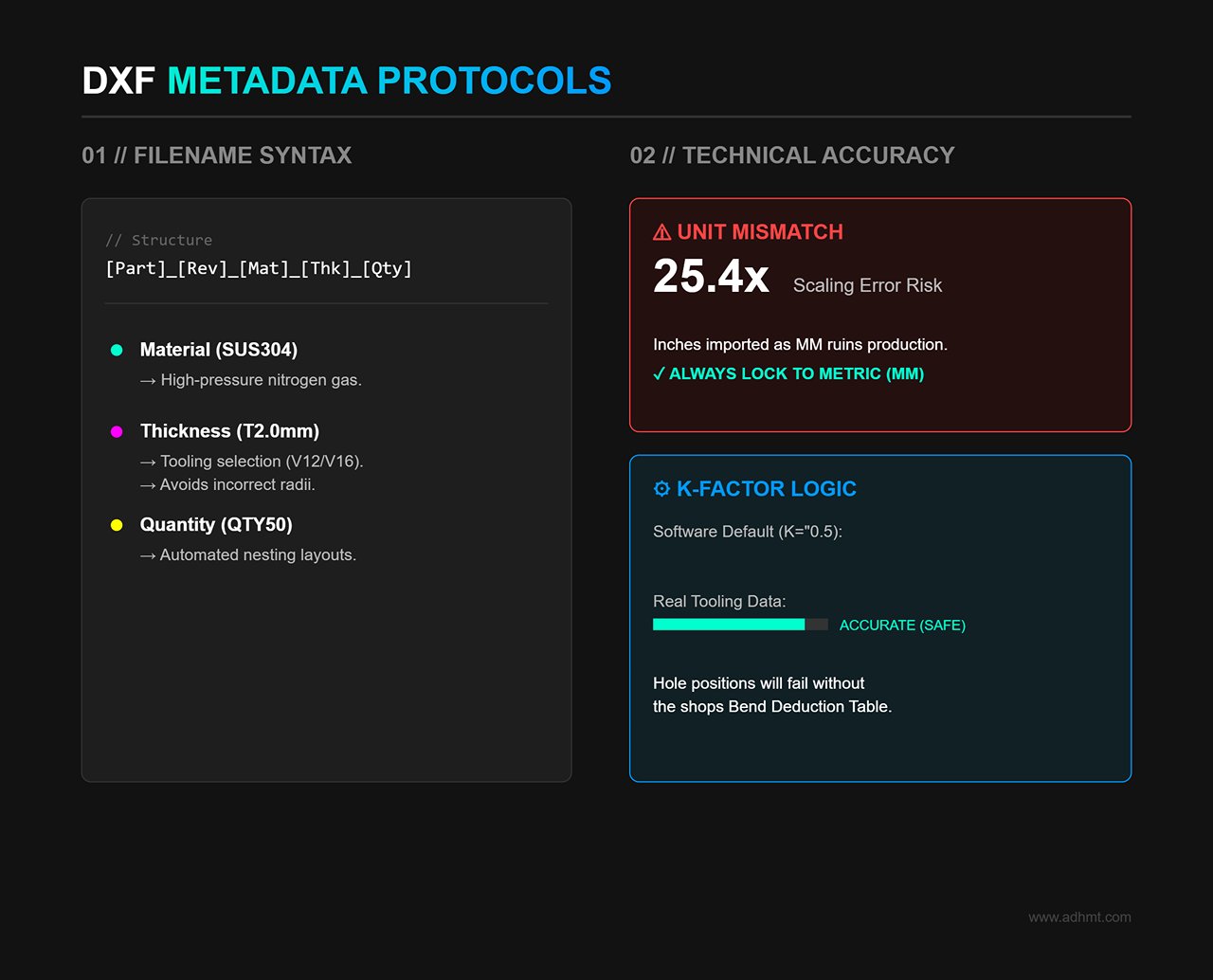
Never name a file Part1.dxf. The filename should function as a production instruction, covering five core elements: [PartNo]_[Revision]_[Material]_[Thickness]_[Quantity].dxf
SUS304: Informs the laser operator to use high‑pressure nitrogen assist gas.
T2.0mm: Alerts the press brake operator to select V12 or V16 tooling to avoid incorrect bend radii.
QTY50: Allows nesting software to automatically generate layouts for 50 pieces.
B. The critical K‑factor and unit pitfalls
Unit consistency: DXF files do not enforce units. A 100×100 rectangle exported in inches but imported as millimeters becomes 25.4 times larger.
Rule: Always work in metric (mm) and lock the export scale to 1:1.
The logical loop of flat‑pattern accuracy:
Pain point: Design software defaults (e.g., K=0.5) are theoretical. Actual bend deductions depend heavily on real tooling, particularly V‑opening width.
Solution: The design team must obtain the shop’s actual Bend Deduction Table. Flat patterns in DXF files must be generated using real machine tooling data, not software defaults. Only then will hole positions align correctly after bending.
IV. Controller Integration: Practical Import Guide for Mainstream Systems
A theoretically perfect file is worthless if it cannot survive the final step—importing into the controller. Different CNC systems interpret DXF files differently, and careless import attempts may trigger errors or even cause crashes. This chapter explains the proper workflow from USB to bending action using the most widely adopted systems.
4.1 Delem Systems (DA‑66T/69T) Deep Integration
Delem controllers are known for their openness and are used in most high‑end press brakes. However, that flexibility also means improper import practices can quickly lead operators into configuration trouble.
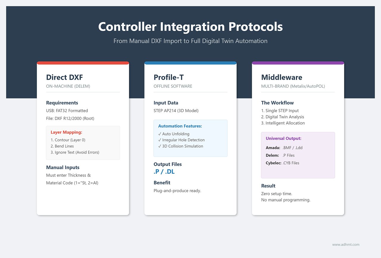
A. Direct DXF Import on the Machine: The survival guide for urgent or small‑batch jobs
If all you have is a 2D DXF and no offline programming software, follow the procedure below to ensure the Delem controller interprets the geometry correctly:
Media preparation: Use a FAT32‑formatted USB drive and place a clean DXF file (R12 or 2000 format recommended) in the root directory.
Layer mapping—the decisive step: After navigating to Products > New Product > Import, the system will display a layer‑selection interface. This is where most beginners fail. The controller cannot guess which lines are contours or bend lines, so you must assign them manually:
Contour: Select your outer contour layer (e.g., white / Layer 0).
Bend Line: Select the bend‑line layer (e.g., red).
Ignore: Be sure to ignore scribe, text, or dashed layers. Warning: If you mistakenly mark a scribe line as a contour, the system will interpret it as a broken outer boundary and trigger an “Open Contour” error, preventing program generation.
Inject physical attributes: Because a DXF contains no thickness, you must manually enter material thickness before generating the simulation.
Thickness: Specify the value to one decimal place (for example, 2.0 mm).
Material: Select the correct material code (typically 1 = Steel, 2 = Aluminum). This choice directly determines the calculated bending tonnage and springback compensation. A wrong selection may cause angle deviation or, in severe cases, damage the tooling.
B. Profile-T Offline Integration: The Gold Standard for Unlocking Full Machine Performance
If your Delem controller supports 3D functionality (DA‑66T or higher), sticking to DXF programming means leaving a large portion of your machine’s capability unused. The best practice is to use the dedicated Profile‑T offline software and feed it 3D models directly.
Process advantages:
Source: Import a STEP AP214 file directly.
Analysis: Click Unfold and let the software automatically detect flange lengths, bend radii, and irregular hole positions.
Simulation: Run the Simulation on a PC. The software uses the machine’s true 3D model—including the exact geometry of backgauge fingers—for full collision detection.
Output: Export a .P (Product) or .DL (Data Link) file.
Value: When operators insert a USB stick and load the .P file, no further setup is required. Bend sequence, tooling, and backgauge positions are all embedded, enabling truly plug‑and‑produce operation.
4.2 The “Middleware” Strategy for Offline Programming Software
In real‑world sheet metal shops, it’s common to see a “mixed‑brand zoo”: domestic machines with Delem controls alongside imported systems from Amada or Trumpf. In such environments, a simple DXF is not universal—each controller speaks its own dialect.
This is where third‑party offline programming tools (such as Metalix MBend, AutoPOL, or Radbend) become the essential “universal translator” that eliminates data silos.
A. Closed vs. Open Ecosystems
Amada (AMNC 3i/F): A highly closed ecosystem. It typically rejects general DXF‑based auto‑programming and requires encrypted .BMF or .Ldd files generated through its own Dr. ABE_Bend or VPSS 3i systems. Drawing directly on the controller or importing DXFs on‑machine is extremely inefficient.
Cybelec (ModEva/CybTouch): DXF is supported, but for complex multi‑bend parts, its computational power is often weaker than that of PC‑based software.
B. Practical Strategy: Program Once, Deploy to Any Machine
To break through brand barriers, mature factories build a STEP‑centric middleware workflow:
Unified Input: Regardless of machine brand, the design department outputs a single format—STEP AP214.
Intelligent Distribution (PC‑based CAM): CAM engineers import STEP files into third‑party software such as Metalix MBend. The software contains digital twins of all machines in the shop, including varying tonnages, open heights, and backgauge configurations.
Automatic clearance computation: The software evaluates, for example, “The Amada’s backgauge fingers are too wide—bend 3 will collide. This job must be assigned to the Delem machine instead.”
Multi‑format output: Once verified, the software generates the appropriate machine code:
.P file for Delem machines.
.BMF file for Amada machines.
.CYB file for Cybelec machines.
This workflow eliminates the need for operators to manually program at the machine using paper drawings. Setup time drops to nearly zero—an essential milestone for any sheet metal factory moving toward intelligent manufacturing.
V. Diagnostics and Optimization: Solving Pain Points and Boosting Efficiency
When an alarming red error box pops up on the controller or an expensive sheet is scrapped on the first hit, the workshop atmosphere can freeze instantly.
But don’t panic—data from field service shows that 90% of import failures stem not from complex system issues but from basic oversights during file preparation. This chapter presents a standardized diagnostic workflow and automation strategy to shift you from reactive troubleshooting to proactive prevention.
5.1 Troubleshooting Tree for Import Failures
This is an emergency guide designed for frontline operators. Print it and post it next to the CNC control cabinet as the standard SOP whenever a machine halts.
Analysis: Most industrial controllers (including Delem and Cybelec) only support the FAT32 file system. If your USB stick is formatted as NTFS or exFAT, the machine simply won’t detect it.
Solution: Prepare a dedicated USB drive under 32 GB and format it as FAT32 on a PC.
Root Cause B: Illegal characters in the filename
Analysis: Many legacy systems cannot parse Chinese characters, spaces, or special symbols such as #, &, ().
Solution: Follow strict naming rules. Use only English letters, numbers, and underscores.
Incorrect example: Bracket V2 (final).dxf
Correct example: BRACKET_V2_FINAL.dxf
Root Cause C: DXF version too new
Analysis: DXF formats from 2018 onward contain complex binary structures that older controllers cannot decode.
Solution: Always save the file as AutoCAD 2000/2004 ASCII DXF.
Symptom 2: "Contour Not Closed" or "Open Loop"
Observation: The system cannot determine inner and outer boundaries, so it cannot generate a toolpath.
Root Cause: Microscopic gaps (Gap < 0.1 mm) in the contour or invisible overlapping lines.
Solution:
On-site quick fix (Delem system): Go to Settings > General and locate the Connect Distance parameter. Temporarily increase it from the default 0.01 mm to 0.1 mm to force the system to ignore micro‑gaps.
Permanent fix: Return to your CAD software and use PEDIT > Join to fully close all segments, or run OVERKILL to eliminate overlapping entities.
Symptom 3: Bend Lines Missing
Phenomenon: After import, only the outer contour appears. All internal bend lines have vanished.
Root cause: Layer mapping failed. The layer containing bend lines was interpreted as a non‑machining or etching layer.
Solution:
Delem / Cybelec: In the Layer Mapping panel during import, verify that the red layer (or your designated bend-line color) is assigned the Bend Line attribute. Never assign Ignore or Contour.
Amada: Ensure the bend-line color matches the machine’s parameter table (typically Color 1 = red) and that the linetype is Continuous. Dashed lines may be filtered out in some versions.
Symptom 4: Simulation Passes but Real Machine Collides (Ghost Collision)
Phenomenon: Simulation shows no issues, yet during actual bending, the flange sweeps into the backgauge beam.
Root cause: Dimensional deception in 2D DXF. DXF files only contain planar data and lack Z-height, so the controller assumes the part is flat and cannot compute its spatial motion during bending.
Solution:
Abandon 2D thinking: For boxes, deep U‑profiles, or complex geometries, always program using STEP. Only in a 3D environment can the system calculate the true volumetric envelope during rotation and apply side‑approach or special motions to avoid collisions.
5.2 Automation Efficiency Toolbox
Fixing errors is merely passing the exam. Achieving world‑class productivity requires tools that eliminate repetitive manual tasks. The following three toolkits can boost your programming efficiency by more than 300%.
A. The Batch Macro
Pain point: Designers manually open 50+ SolidWorks parts per day just to adjust views, hide layers, and save as DXF—slow and error‑prone.
Tool: SolidWorks Task Scheduler or a custom VBA macro.
Strategy: Configure an automation script to batch‑convert all .SLDPRT files in a project folder into standardized .DXF files. Include logic for automatic layer mapping, flat pattern extraction, and rule‑based renaming.
Benefit: Saves 1–2 hours of senior engineer time per day, with 100% consistency in output formatting.
B. The Digital Gatekeeper
Pain point: Faulty DXFs—wrong scale, hole too close to bend line—reach the shop floor and only fail after cutting or bending, resulting in scrap.
Tool: Flux or verification software such as Lantek / CADMAN‑SDI.
Strategy: Run a pre‑check before sending files to the laser. Define automated rules to verify:
Are contours fully closed?
Is any flange smaller than material thickness?
Are holes located inside deformation zones?
Benefit: Scrap is caught on-screen instead of in the scrap bin.
C. Scan‑to‑Load Workflow
Pain point: Operators hunt through hundreds of files on the controller for PART_123_REV_B.dxf, easily selecting the wrong or outdated version.
Tool: Industrial‑grade USB scanner + barcode-enabled work orders.
Strategy:
Print the filename as a barcode (Code 128 or QR) on ERP/MES work orders.
Plug the USB scanner into the press brake controller.
The operator simply scans the work order, and the controller automatically loads the correct program.
Benefit: Changeover time drops from 5 minutes to 5 seconds, eliminating the risk of loading incorrect programs.
If your factory is evaluating upgrades to smart workflows, consider exploring solutions from ADH Machine Tool, or reach out directly to contact us for tailored consulting.
VI. Resources and Actions: The Deployment Package from Office to Shop Floor
If the earlier chapters covered the theoretical foundation of bending workflows, this section delivers the actionable playbook for shop‑floor execution. Even the cleanest file formats fail without disciplined process control.
To bridge the gap between design (Office) and execution (Shop Floor), we present a benchmark‑validated collaboration protocol and forward‑looking technology roadmap.
6.1 Recommended Team Collaboration SOP
Data loss often occurs in the gray zones between departments. To eliminate ambiguity and blame-shifting, print the following responsibility matrix as an A3 poster and display it in the process room and next to CNC cabinets as a non‑negotiable rule.
6.1.1 File Transfer SOP Responsibility Matrix
This is more than a table—it is a digital handshake agreement between departments.
Core Process Stage
Responsible Role
Input Data Flow
Output Deliverable
Release Criteria (Gatekeeper)
Time Control
Design Output
CAD Engineer
3D solid model (.SLDPRT)
STEP AP214 + cleaned DXF
✓ Passed CADMAN‑SDI/Flux verification ✓ No duplicate lines, no open contours
Within 24h after order release
Process Programming
CAM Engineer
STEP + DXF
Native controller code (.P / .BMF / .GEO)
✓ No collision alarms in offline 3D simulation ✓ 100% tooling‑library match
6.1.2 Manage Versions as You Would in Software Development (Version Control)
Put an end to the endless “Final_Final_V2” circus in file naming. Adopt a Git‑style versioning mindset common in engineering workflows to ensure the shop floor always accesses the most up‑to‑date revision.
The Iron Rule of Version Control:
V01: Initial design draft, prepared solely for quotation or preliminary evaluation.
V02: Process-revision version, validated through simulation and updated to correct clearance slots or unfolding coefficients.
V03: Production iteration release, with the back-gauge position refined based on first‑article feedback.
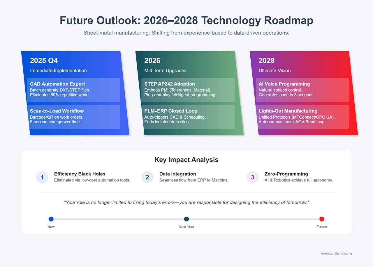
Sheet‑metal manufacturing is undergoing a seismic shift from experience‑based decision‑making to data‑driven operations. As a manager, your role is no longer limited to fixing today’s errors—you are responsible for designing the efficiency of tomorrow.
🚀 Immediate Implementation (2025 Q4): Eliminating Efficiency Black Holes
You don’t need cutting‑edge technology to unlock major productivity gains—start multiplying your efficiency today with simple, low‑cost tools:
CAD Automation Export Macro: Use SolidWorks Task Scheduler or custom VBA scripts to generate DXF and STEP files in one batch, complete with automatic layer‑color mapping. This streamlined process can eliminate roughly 80% of repetitive engineering work.
Scan-to-Load Workflow: Convert the file name into a barcode or QR code and print it on the work order. Equip the press brake with a USB barcode scanner so the operator can simply scan—one quick beep—to instantly load the correct program. This cuts changeover time to just 5 seconds and eliminates the possibility of human error when entering file names.
📈 Mid‑Term Upgrades (2026): Toward Deeper Data Integration
Widespread Adoption of STEP AP242: This next‑generation STEP format carries not only geometric data but also embeds PMI (Product Manufacturing Information), including tolerances, surface‑finish requirements, and material grain direction. High‑end systems like the Delem DA‑69T can directly interpret these metadata elements, enabling truly plug‑and‑play intelligent programming.
PLM–ERP Closed Loop: Once an order is entered into the ERP system, it automatically triggers the CAD design workflow, generating bending programs and scheduling them without manual intervention. Siemens and Trumpf have already demonstrated prototypes of this seamless integration, signaling the end of isolated data silos.
🔮 Ultimate Vision (2028): Advancing Toward a Truly “Zero‑Programming” Era
AI-Driven Voice Programming: Future controllers will understand natural speech. Say, “Create a program for this 2 mm stainless steel box: first two bends at 90 degrees, next two at 45 degrees, avoid scratching the side surface,” and the AI will generate flawless machine code in just three seconds.
Robotic bending cells with universal protocols: With the standardization of MTConnect and OPC UA protocols in sheet metal equipment, machines from different brands will share the same data language. Laser cutting, AGV transport, and robotic bending will form an unmanned closed loop, achieving "Lights-out Manufacturing."
Robot Bending Cells and Unified Protocols: As MTConnect and OPC UA become standardized across sheet‑metal equipment, machines from different brands will begin speaking the same data language. Laser cutting, AGV transport, and robotic bending will merge into a fully autonomous loop, enabling true lights‑out manufacturing.
Technology is merely the tool; disciplined execution is the real competitive edge. To ensure this guide delivers tangible value, roll out the following actions during next Monday’s morning briefing.
Week 1 – Standardization: Conduct company-wide training on the unified DXF layer color conventions (for example, red for bending, white for cutting), and ensure these standards are permanently embedded into the export templates of all CAD software.
Month 1 – Software Upgrade: Evaluate and purchase an offline programming solution compatible with the factory’s machine models (such as Profile‑T, Metalix, or AutoPOL), and establish a targeted three‑month return‑on‑investment (ROI) period.
Quarter 1 – Mechanism Setup: Create a “Defect Review Group” that meets for 30 minutes each week to analyze file‑import failures, using these reviews to drive continuous improvements in file quality on the design side.
Year 1 – System Integration: Introduce an automated drawing‑validation system (such as CADMAN‑SDI) with the goal of reducing scrap caused by file errors by 90%.
Conclusion: In the era of digital manufacturing, a flawless bending drawing is a kind of sacred contract linking virtual design with physical production. When you follow this guide with rigor—cleaning every DXF line, validating every STEP model—you are delivering more than a part. You are delivering certainty and dignity to industrial manufacturing.
Looking for Machines?
If you're looking for sheet metal fabrication machines, then you've come to the right place!
Not sure which machine is right for your sheet metal product? Let our knowledgeable sales team guide you in selecting the most suitable solution for your needs.