When the “Power Off” indicator on the control cabinet lights up, your hand might instinctively reach for the hydraulic valve block—stop right there. That eerie stillness doesn’t mean safety; it means potential energy waiting to be unleashed. Most shearing machine accidents don’t occur during normal operation, but in the first minute of maintenance—when someone trusts a switch instead of the laws of physics. Before you pick up that wrench, make sure the first 60 seconds won’t also be your last. If you are operating a Swing Beam Shearing Machine or Guillotine Shearing Machine, this initial caution is crucial.
The First 60 Seconds: Pre-Touch Safety Triage for Valves
Press Stop, Lock, and Listen: Safety Confirmation Before Opening Guards
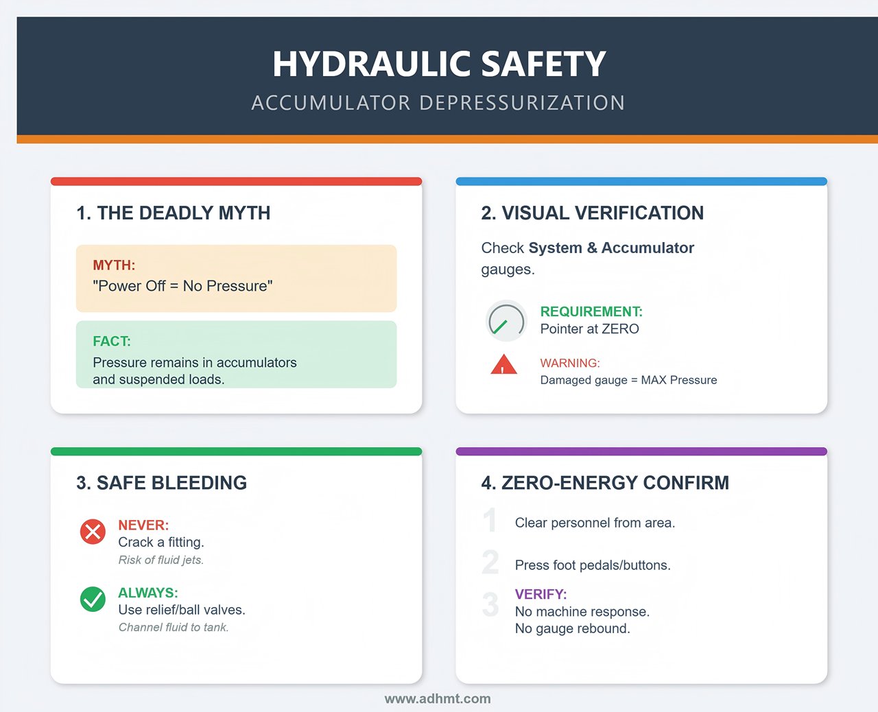
The emergency stop (E‑Stop) is only the first step, not the last. Always ensure the blade carrier is at top dead center (TDC) or mechanically supported. If it’s left suspended, gravity becomes your biggest hazard—one loss of pressure, and a ton of steel can drop in an instant.
After cutting off the main power, strictly follow the Lockout/Tagout (LOTO) procedure. This applies not just to the main electrical isolator but also to the hydraulic pump breaker and auxiliary air supply. Attaching your personal lock means, “Until I’m back, nobody restores power.”
Once the locks are in place, don’t rush to disassemble anything. Stand still for five seconds and listen. Any hissing, liquid flow, or high‑frequency noise indicates trapped pressure still venting. If you hear continuous oil flow, it means the accumulator or piping is relieving through a bypass—do not loosen any fittings. High‑pressure oil can penetrate skin, and air sucked in during decompression may cause later system failures.
Verify the Accumulator Is Fully Depressurized (The Step Operators Most Often Skip)
“Power off equals no pressure” is a deadly misconception in hydraulic maintenance. As long as the system includes an accumulator, vertical cylinder, or suspended load, pressure still remains.
Never rely on guesswork—look at the pressure gauge. Check both the main system and accumulator branches. If the pointer isn’t at zero, treat it as pressurized. If the gauge is damaged or questionable, assume it’s showing maximum pressure.
Never attempt to “crack a fitting to bleed off oil.” That reckless move can cause unpredictable fluid jets capable of injury and may draw air into the system. Always depressurize through the designated relief valve or accumulator ball valve to channel fluid safely back to the tank.
Finally, once personnel are safely clear, perform a “zero‑energy verification.” Try pressing the foot pedal or start button—confirm that the blade carrier, hold‑down cylinder, and back gauge show no response, and that the pressure gauge does not rebound (to rule out backflow through check valves). Only then is the system truly isolated. For detailed maintenance specifications, refer to our downloadable brochures that include hydraulic schematics and safety checklists.
Walk‑Around Inspection: Detect Leaks, Loose Bolts, or Blocked Sensors
Before picking up a multimeter or pulling a valve spool, take a full walk around the machine. Many so‑called “complex failures” are actually visible physical abnormalities.
Start by looking down. Fresh oil spots under the frame or near the accumulator base, along with a drop in the oil tank level, often point to leaks. Next, inspect all connections—check the pump base, motor mount, and valve block fasteners. Loose clamps can cause vibration in high‑pressure lines, leading to fatigue cracks—a common cause of accuracy drift.
Pay special attention to sensors. Limit switches, encoders, and light curtains are often blocked by metal shavings, oil, or scrap material, throwing signal logic into chaos (for example, a normally closed circuit acting as normally open). Cleaning these interferences can instantly resolve what seemed like a “controls failure.” Finally, trust your nose—do you smell burnt insulation or scorched oil? That’s often a direct indicator of motor overload or chronic overheating.
When a shear machine refuses to work, most technicians make the same mistake: suspecting the most expensive part—the hydraulic pump. The foot pedal goes down, the blade stays still, and they rush to order a new pump or drain the tank.
That’s an expensive misjudgment. Before unbolting anything, you need to look at the scene like a detective. If the previous “safety triage” kept you safe from the machine, this section will keep you safe from being misled by false symptoms.
If your Guillotine Shearing Machine shows similar symptoms, precise fault localization prevents costly downtime. Accurate inspection and data recording help service specialists quickly identify faulty hydraulic components—feel free to contact us for remote diagnostic assistance.
Scenario A: Machine Fails to Cycle (Tracing Power and Pressure)
Reading Pressure Gauge Clues to Identify Fault Sources
The main pressure gauge is the hydraulic system’s “ECG.” When the machine powers up but refuses to move, don’t rush to press buttons—watch the gauge instead (usually located on the valve block or tank side). Its behavior can narrow your troubleshooting range by 80% in under ten seconds.
Start the hydraulic pump and observe the needle:
- Needle stays at zero (even after 5 s of pump operation) – The electrical side is likely fine (motor is spinning), but the hydraulic source isn’t building pressure. That doesn’t necessarily mean the pump is bad. First check if the motor coupling is loose or slipping, letting the motor spin without driving the pump. Next, inspect the relief valve—it may be stuck open due to debris, sending oil straight back to the tank. Tip: Try turning the main relief valve clockwise by a quarter turn. If there’s still no response, the issue likely lies at the pump suction port (clogged filter) or a jammed relief spool.
- Needle fluctuates or reads 20 % below rated pressure – If cutting 12 mm steel requires 20 MPa but the gauge barely reaches 15 MPa and shakes violently, that’s a classic sign of cavitation. The pump is drawing air or the filter is clogged with contaminated oil. Advanced technique: Press a long screwdriver against the pump housing and place your ear on the handle. A gritty “grinding” noise means internal wear or air ingestion; a smooth humming sound suggests the pump is fine—check relief valve settings or internal cylinder leakage instead.
- Needle shows normal pressure but the blade doesn’t move – The most deceptive condition of all. Pressure is present, so the heart (pump) and arteries (lines) are fine—the fault lies in the brain (controls) or limbs (actuators). Pay attention not only to the pressure value but also to how fast it responds. Old gauges with strong damping can lag by two seconds—don’t be fooled by false stability.

The Solenoid Valve “Click” Test: Distinguishing Electrical From Hydraulic Issues
Once the gauge confirms the hydraulic supply is ready, the next step is to verify whether the command reaches the actuator. The sound of a solenoid valve clicking is the gold standard for distinguishing electrical faults from hydraulic jams.
Locate the solenoid valve group controlling downstroke, return, or clamping. Have an assistant press the foot pedal while you "listen in."
- PLC output light on but no sound – This is a purely electrical fault. The PLC issued a command (light on), but the coil didn’t actuate. Measure voltage across the coil terminals (typically DC 24 V or AC 220 V). If no voltage, check relay contacts or wiring looseness. If voltage is present but no magnetic response, the coil is burnt out (infinite resistance) or open-circuited. Pro tip: Sometimes a coil reads normal resistance cold but fails when heated. Test with a spare coil or use a screwdriver to feel for magnetism when energized.
- Distinct double click (“on–off”) but cylinder doesn’t move – Power is reaching the valve and its spool is shifting, but oil isn’t flowing. This usually means a stuck spool or blocked hydraulic passage. The spool may be moving only halfway or the internal orifice may be clogged with seal debris. Don’t rush to replace the valve—try manually pushing the spool (see below). If it still won’t move, remove and clean it with No. 46 hydraulic oil.
- A dull or single thud: This usually indicates backpressure interference. It often occurs when the accumulator’s nitrogen pressure is abnormal, leading to excessive pressure in the return line and hindering spool movement. Check the accumulator’s charge pressure and inspect the check valve for leaks.

Limit Switches and Interlocks: Finding Hidden Sensors That Halt Shearing
If all gauges and solenoids test correctly yet the machine remains completely still, it’s usually because it “believes” it’s in a hazardous state or not properly reset. One of those unseen “watchdog sensors” has effectively locked the control circuit.
- “Gray/Red” icons on the PLC screen: Modern shear machine PLC displays visually show sensor states. Focus on checking:
- Upper/Lower Blade Carrier Limit Switches: Often misread due to vibration displacement or iron filings covering the sensor face.
- Backgauge Zero Reference: Abnormal encoder readings will block the shearing function.
- Clamping Cylinder Upper Limit: Proximity switches can get coated with oil sludge, making the system think the hold-down foot hasn’t lifted—preventing the next cycle.
- All indicators green, but no movement—The safety interlock trap: If the PLC display shows normal status, the culprit may be an unmonitored hardwired interlock.
- Light curtain protection: Oil contamination can weaken the emitter signal, causing a “false obstruction.” The first step is to clean the lens.
- Side/Rear Door Safety Switches: Many older machines have bypassed or damaged door switches. If the dual-channel safety relay’s EDM (External Device Monitoring) circuit is open, the power output will be cut off directly, and the PLC may only show a vague “Emergency Stop” fault.
- Foot Pedal Micro Switch: The internal micro switch in the foot pedal often fails due to moisture ingress or spring fatigue. Use a multimeter in continuity mode to check the contacts—it's a basic skill for diagnosing false trigger conditions.
PLC Appears Normal but the Ram Won’t Move — How to Safely Perform a Pump Override Test
If you’ve ruled out all previous faults—PLC shows no alarms, pressure is good, and sensors are in place—but the machine is still unresponsive, you’re likely dealing with a “ghost fault.” These are often caused by oxidized I/O contacts or lost feedback signals from the proportional valve. At this stage, a controlled manual override test is required to bypass the logic temporarily and test the circuit safely.
Warning: Perform this procedure only after properly executing the LOTO (Lockout/Tagout) release under strict supervision. Ensure there are no objects under the blade carrier, and the operator remains outside the safety enclosure.
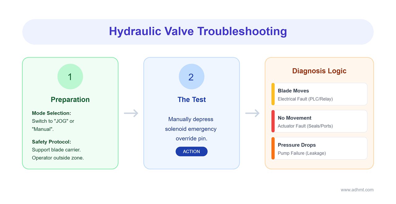
- Preparation: Switch the machine to “JOG” or “Manual” mode. Mechanically support the blade carrier (especially if testing the return stroke) to prevent a drop due to pressure loss.
- Manually activate the valve: Most hydraulic directional valves have a built-in emergency override pin. Use a blunt tool (e.g., a hex key) to gently depress the solenoid spool for the downstroke control.
- If the blade carrier moves: The hydraulic circuit is functioning properly. The fault is definitively on the electrical side—likely a faulty PLC output, poor relay contact, or loose connector.
- If the blade carrier still doesn’t move: The issue lies within the hydraulic actuator. Possible causes include internal leakage from damaged piston seals in the main cylinder or a blocked pilot port in the main pressure valve.
3. Distinguishing pump “no-load” conditions: While manually pressing the valve, observe the pressure gauge. If pressure drops instantly and fails to recover, the pump flow is insufficient to build working pressure—likely due to severe internal leakage.
Scenario B: The Machine Cycles Normally but Shearing Quality Is Poor (Diagnosing via Scrap Analysis)
Through this systematic procedure, you move from random part replacement to precise fault localization. At this point, you’ll know whether the issue lies in the “hydraulic bloodstream” or the “electrical nervous system.” If the machine now moves but produces rough or uneven cuts, the problem shifts from “motion failure” to “precision failure”—which leads us to the next section: Diagnosing Shearing Quality Defects.
When shearing quality deteriorates, most maintenance personnel instinctively remove the blades for sharpening. That’s an expensive mistake. In most cases, the blades themselves are not the main culprit—or at least not the only one.
True diagnostic experts don’t reach for tools first—they pick up scrap from the floor. Scrap is the machine’s “forensic evidence.” An experienced engineer can read the microscopic texture of a sheared edge and, without touching the control panel, infer internal stress distribution and clearance settings. In this section, we’ll learn how to translate scrap clues into mechanical adjustment parameters.
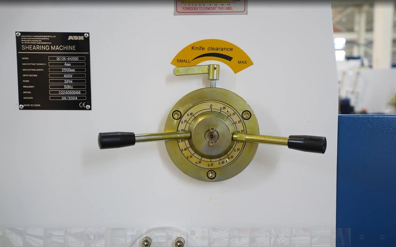
Blade Clearance: A 30-Second Check That Solves 60% of Quality Issues
Blade clearance is the lifeline of a shear. Because metal is ductile, incorrect clearance causes unwanted material deformation before fracture. Studies show that 60% of shear quality issues—whether excessive burrs or rough edges—stem from clearance exceeding 5% of material thickness.
Before reaching for tools, perform this 30-second quick inspection:
- Sample: Pick up a freshly sheared scrap piece.
- Position: Use manual or jog mode to bring the ram to bottom dead center (ensure LOTO), locating the overlapping cutting area of the blades.
- Gauge: Insert a 0.05 mm feeler gauge between the blades to test the clearance.
- Standard: The feeler gauge should slide smoothly, neither binding nor too loose.
- Verification: Measure at three points—left, center, and right. If deviation exceeds 0.1 mm, the blade beam has likely deformed or lost parallelism and must be realigned immediately.
If clearance needs adjustment, refer to the following standard settings for carbon steel (for harder materials like stainless steel, increase by 10%):
| Material Thickness (mm) | Recommended Blade Clearance (mm) |
|---|---|
| 1 - 3 | 0.1 - 0.2 |
| 3 - 6 | 0.2 - 0.4 |
| 6 - 10 | 0.4 - 0.6 |
| 10 - 16 | 0.6 - 1.0 |
Adjustment Strategy: After completing the LOTO procedure, manually lower the blade carrier and secure it with blocks. Loosen the four bolts fixing the lower blade, then fine-tune using the jack screws. Always follow the “left–center–right” synchronized adjustment principle, verifying each iteration with a feeler gauge, and retighten bolts afterward.
Pro Tip: For newly installed blades, don’t aim for perfect clearance immediately. Leave an extra 0.2 mm gap for a running-in phase. Fresh blades are extremely sharp; too tight a clearance may produce flawless initial cuts but leads to micro-chipping and shorter blade life.
“Chalk Test”: Visualizing Material Creep to Diagnose Clamping Failures
When cuts appear slanted, inconsistent in length, or show wavy edges, the problem often lies not with the blades but with the clamping system. Insufficient clamping force allows the sheet to shift microscopically at the moment of shear—a phenomenon known as material creep. Though invisible to the eye, the “chalk test” can make it visible.
Procedure:
- Evenly coat the clamping area of the sheet with white chalk.
- Start the hold-down device (without engaging the shear). After it clamps firmly, raise it back up.
- Observe the chalk marks on the sheet.
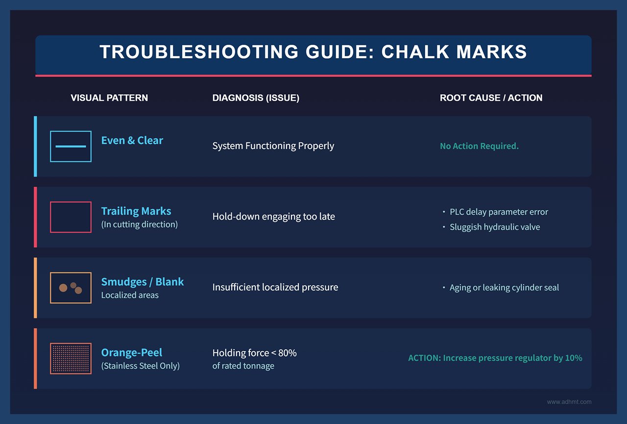
Interpreting the Chalk Marks:
- Even and clear – The hold-down system is functioning properly.
- Trailing marks in the cutting direction – The hold-down is engaging too late, after the blade makes contact. This typically indicates a PLC delay parameter error or a sluggish hydraulic valve response.
- Localized smudges or blank areas – The corresponding hold-down cylinder’s seal may be aging or leaking, resulting in insufficient localized pressure.
- Orange-peel texture (specific to stainless steel) – If the stainless-steel surface shows a dimpled, orange-peel-like texture, the holding force is below 80% of the rated tonnage. Due to its high hardness, stainless steel requires higher clamping pressure to prevent slippage. Try increasing the pressure regulator setting by 10%.
If scrap analysis shows creep displacement exceeding 2 mm and the chalk test confirms unstable holding, replace the cylinder seal directly. Simply boosting system pressure will only overheat the pump and will not fix a physical leak. After testing, thoroughly clean off all chalk residue with alcohol to prevent misleading results in the next batch. You can compare normal edge profiles from standard Guillotine Shearing Machine operations in the product documentation.
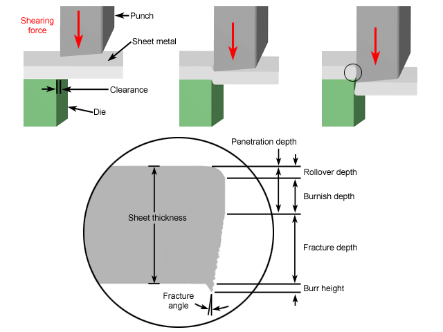
Burrs, Bending, and Twisting: What the Edge Profile Reveals About Setup Issues
Don’t just check whether the cut edge looks smooth—read the edge profile of the scrap like an ECG trace. A proper sheared edge consists of four distinct zones: Rollover, Shear Zone, Fracture Zone, and Burr. The ratio among these zones directly reflects the machine’s setup condition.
Edge Diagnosis Logic:
- Large burrs (>0.2 mm) – If burr height exceeds 20% of the shear zone thickness and shows bright, drawn-out streaks, it usually means the clearance is too large or the blades have dulled. Reduce clearance by 0.05 mm and retest.
- Bowing – The sheet arches at the center. This is a combined result of insufficient hold-down force and excessive clearance. The material lifts during shearing and escapes laterally due to loose spacing.
- Twisting – The sheet twists like a propeller. This is a clear sign of poor parallelism of the blade beam or an excessive rake angle. Check the guide clearance or re-shim the knife seat accordingly.
| Symptom | Profile Characteristics | Root Cause |
|---|---|---|
| Large burr | Burr height > 25% of thickness | Excessive clearance / Dull blade |
| Bowing | Bright shear zone < 30% | Weak hold-down force |
| Twisting | Asymmetric rollover | Tilted blade beam / Excessive rake angle |
| Diagonal cut | Fracture zone length > 40% | Material creep during shear |
Special Caution for AHSS (Advanced High Strength Steel): Sometimes AHSS shows a deceptively smooth edge—no burrs but with micro-cracks. These materials have very high work-hardening rates (above HV400). If edge tensile tests show elongation below 20%, adjust the setting (usually by increasing clearance) even when burrs are absent; otherwise, cracking will occur in subsequent bending operations.
Dull, Chipped, or Misaligned — How to Diagnose Blade Issues Without Dismantling
Removing the blades takes time and carries safety risks. By mastering both “listening” and “feeling” techniques, you can diagnose blade conditions accurately without disassembly—with up to 95% accuracy.
Dullness Diagnosis:
- Visual: The cut shows a wavy, serrated appearance with no sharp fracture line. Under 10× magnification, if you see a reflective crescent band wider than 0.3 mm along the edge, the blade has been rounded and needs regrinding.
- Auditory: The cutting sound is muffled, lacking the crisp metallic snap typical of a sharp blade.
- Scrap Evidence: The rollover zone is very thin (<10% of thickness), showing that the blade is compressing the material instead of penetrating it.
Chipping Diagnosis:
- Visual: The cut edge displays periodic step-like voids or missing sections.
- Auditory: The shearing process produces localized metallic “tinks” as stress is released from the chipped areas. This is common when frequently cutting harder materials such as Q345 steel. Once chipping occurs, only welding repair or replacement will fix it; grinding cannot correct deep fractures.
Misalignment Diagnosis:
- Visual: The entire cut edge shows a gradual step offset, with a burr height difference greater than 0.1 mm between the left and right sides.
- Tactile: Lightly tap the back of the blade with a wooden mallet (after applying LOTO). A dull or inconsistent tone suggests uneven shimming or foreign particles behind the blade seat.
Decision Chain: First, cut a piece of soft aluminum scrap to verify the baseline smoothness of the cut face. If abnormalities persist, use a stethoscope against the blade mount to listen. A dull edge produces no high-frequency resonance, a chipped edge yields local dead spots, and misalignment causes an overall tonal shift.
- Dull → Regrind on-site or send for servicing.
- Chipped → Weld-repair or replace.
- Misaligned → Adjust the knife seat with copper shims; this can save up to 80% of unnecessary disassembly time.

Learn to read the scrap, and it becomes the “oscilloscope of a resourceful mechanic.” From blade alignment to hold-down behavior and edge morphology, each clue links to the physical root of the problem. The next challenge is mastering the toughest task—how to properly service the blades themselves.
When facing hydraulic failures, most technicians instinctively drain the oil or replace the pump and seals—an expensive mistake. A true hydraulic diagnostician never removes a single oil tank bolt before pinpointing the fault.
Now, imagine your shear’s motor is running but the blade frame doesn’t move or lacks force. Don’t rush to replace the pump or dismantle the cylinder. This section explains how to use a stethoscope, a high-intensity flashlight, and simple isolation tests to diagnose 90% of core hydraulic issues—without wasting a drop of oil. This marks the crucial shift from guesswork to precise diagnosis, paving the way for effective repair in the next phase.
Rapid Hydraulic System Inspection—No Draining Required
Pump Cavitation vs. Air Ingress: The Truth Behind the Noise
Abnormal noise from a hydraulic pump is a cry for help from the system. Yet, 80% of technicians fail to distinguish between cavitation and aeration. Both sound noisy, but the root causes differ entirely: cavitation means the pump is “starving” (oil supply insufficient), while aeration means it’s “breathing air” (air leak into suction line). Misdiagnosis can lead to pointless pump replacements with the problem still unresolved.
How to Differentiate by Sound:
By frequency (spectrum analysis):
- Cavitation: Produces a steady, high-pitched whine similar to sandpaper rubbing on metal. It occurs as oil vaporizes in low-pressure zones and implodes in high-pressure ones. On a smartphone spectrum analyzer, the peak typically stays near 8 kHz. Common causes include a clogged suction strainer, low oil level, or excessively viscous oil in cold weather (e.g., using #46 hydraulic oil in winter).
- Air Ingress: The sound is irregular and harsh, like a gurgling noise or the clattering of marbles rolling inside a metal can. The noise fluctuates intermittently with pressure changes, and its spectrum is diffuse, typically below 5 kHz. The most common causes are a loose suction-line fitting or a failed shaft seal.
Foam Observation and Sealing Test: Remove the oil tank cap and check the surface—if a large amount of foam is churning, air is likely entering the system. To pinpoint the exact intake location without disassembling the circuit, apply shaving foam or heavy oil around the suction fittings, flanges, or shaft seals while the pump is running. If the noise instantly disappears or becomes noticeably softer, the leak has been located—the negative pressure drew the foam into the crack, temporarily sealing it.
Cylinder Seal Leakage: Verifying Internal Leaks Using a Flashlight Test
When the shear beam descends slowly or slips during pressure holding, many assume an internal cylinder leak (piston seal failure allowing high-pressure oil to bypass to the return side). However, before dismantling the heavy cylinder, you need concrete evidence.
Non-Invasive Diagnosis Using Light:
White-Light Flicker Test (Detecting Internal Leakage): Stop the cylinder at mid-stroke and shine a strong flashlight at a low angle across the piston rod’s oil film. Have the operator apply brief pressure pulses.
- If the reflected light on the rod surface shows rhythmic “flicker or jitter” or the oil film pattern vibrates noticeably, it usually indicates that high-pressure oil is breaching the piston seal and impacting the low-pressure side—causing micro-vibrations of the piston rod.
- If the reflection remains steady, the issue likely lies with the pressure-holding valve or pipeline, not the cylinder itself.
UV Fluorescent Tracing (Detecting Micro-Leaks): For leaks too small to detect visually, add a hydraulic-grade fluorescent dye to the tank (typically at a 1:1000 ratio) and let the oil circulate for 30 minutes. Then inspect under a 365 nm ultraviolet light in a dark environment.
- Rod Base: A bright yellow-green glow around the dust seal indicates the rod seal has failed.
- Cylinder Barrel: Any glowing areas suggest pinholes or cracked weld seams.
This method can reveal pinhole-sized leaks invisible to the naked eye, preventing misdiagnosis as surface oil stains.
Identifying the True Source of Pressure Loss Under Load
If the pump runs quietly and the cylinder shows no apparent internal leakage, yet the system fails to build or sustain pressure—or pressure rises quickly and then drops (load drifts)—you’ll need to isolate the components to trace the true path of pressure loss.
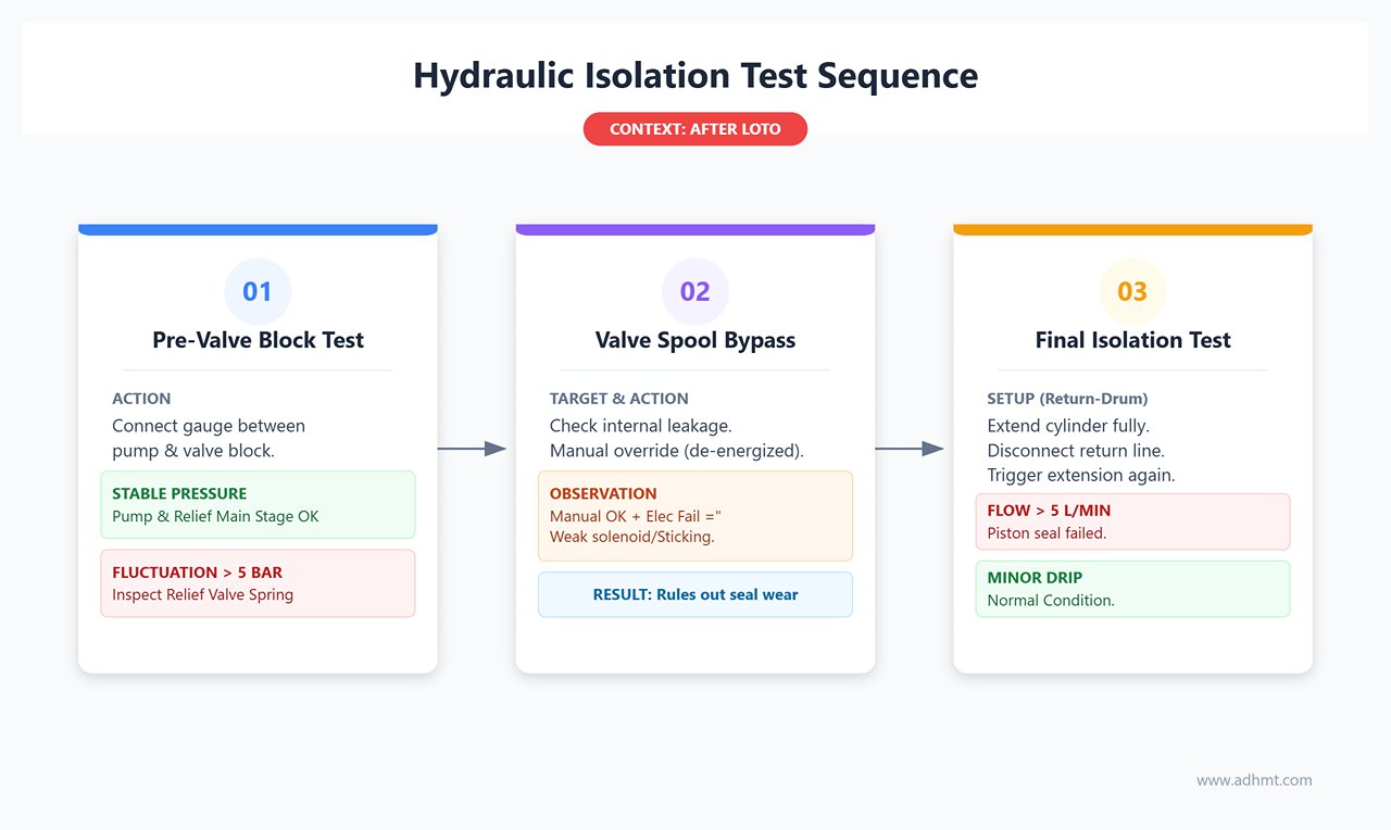
After performing LOTO (Lockout/Tagout), conduct isolation tests in the following order:
- Pre-Valve Block Test: Connect a pressure gauge between the main pump outlet and the valve block. Start the pump and observe whether pressure builds and stabilizes. If pressure is normal here, the pump and main stage of the relief valve are fine. If the pressure fluctuates significantly (over 5 bar), inspect the relief valve spring for fatigue.
- Valve Spool Bypass Test: If you suspect internal leakage in the directional or cartridge valve, manually override it while de-energized (using a screwdriver to rotate the solenoid’s manual knob by 90°). If manual operation holds pressure but electrical control does not, the fault lies in insufficient solenoid force or spool sticking due to contamination, rather than seal wear.
- Final Isolation — Return-Drum Test: The definitive method for confirming internal cylinder leakage.
- Fully extend the cylinder.
- Disconnect the rod-side (return) line and place it into a clean empty oil drum.
- Operate the control again to extend the cylinder (it should already be at full stroke, so theoretically no oil should flow).
- Observe the oil drum: if hydraulic oil continues to flow at more than 5 L/min, the piston seal is completely damaged, allowing high-pressure oil to stream into the return chamber. A minor drip is within normal limits.
Pro Insight: The behavior of the pressure gauge needle can provide additional clues. If it oscillates violently under load (more than ±2 bar), the cause is usually not oil leakage but insufficient nitrogen precharge in the accumulator (typically below 60% of system pressure), preventing it from damping pulsations effectively.
After completing these three diagnostic steps, you should now know whether the issue lies with pump cavitation, internal cylinder leakage, or a bypassing valve spool. In the next section, we’ll move into precise repair procedures targeted at the fault you’ve just pinpointed.
Most operators make a critical mistake when contacting remote support: they send a wide-angle photo of the machine or simply report “the machine won’t cut.” Such vague input forces technicians into a multi-round guessing game, dramatically extending downtime.
Remote specialists don’t need to see the machine’s paintwork—they need its diagnostic “pathology slides.” Before calling after-sales service, use your smartphone and basic tools to collect the following data. This can raise diagnostic accuracy from guesswork to over 95% and enable technicians to provide a clear solution within five minutes of your call.
The “Photo & Measurement” Toolkit: Data to Capture Before Requesting Support
Three Photos That Tell 80% of the Story (Essential Angles)
Forget panoramic shots—you need close-ups and dynamic images that reveal the hydraulic system’s internal behavior. Use your phone’s focus lock and auxiliary lighting to capture the following three critical perspectives:
- Instrument Panel Dynamics (45° Overhead + Slow-Motion Video): A static photo can’t show pressure fluctuations. Record a 10-second slow-motion clip of the entire cutting cycle, focusing on the main pressure gauge. If needle oscillations exceed 2 bar, it typically indicates valve spool leakage; if the needle steps downward during return, it suggests relief valve spring fatigue. Make sure the frame also includes PLC alarm codes and the oil temperature gauge.
- Fault-Point Close-Up (Side Lighting): Whether it’s oil residue on the valve block or chipping on the blade, top-down shots often lose detail due to glare. Illuminate from the side with a flashlight to create shadows that highlight texture. For cutting edges, use the phone’s macro mode or an external magnifier to capture the width of the bright wear band; for optical sensors, photograph any oily reflective spots to help engineers identify false signals.
- Cut Edge and Scrap Cross-Section (45° Side Angle): Scrap pieces act as the “black box” of machine accuracy. Photograph burr height, edge collapse, and torsion patterns. If possible, use a smartphone-mounted infrared thermal camera on the cylinder or valve block—the red “hot spots” reveal internal leak paths where friction heats the oil. This thermal insight goes far beyond what standard photos can show.
Capturing the Sound of Failure: How Audio Helps Diagnose Pump Issues Remotely
Sound is the “heartbeat” of hydraulic pumps and valve assemblies. Describing a “buzzing noise” is subjective—but a recording provides objective data.
Use a screwdriver as a simple stethoscope (tip pressed against the pump housing, handle touching your phone’s microphone) or place your smartphone close to the sound source. Record a 30-second audio clip covering three phases: startup, loaded cutting, and no-load running.
| Frequency Pattern | Description | Recommended Action |
|---|---|---|
| High-Frequency Whine (around 8 kHz) | Steady, sharp tone like bubbles bursting; a classic sign of cavitation. | Check suction line for clogs or air intake. |
| Low-Frequency Gurgling (<5 kHz) | Muffled, irregular rumble indicating air contamination in hydraulic fluid. | Inspect oil tank level and ensure return line is properly sealed. |
| Specific-Frequency Hum (around 200 Hz) | Steady low-frequency vibration suggesting feedback loop interruption or coil hysteresis in proportional valves. | Use a spectrum analyzer app (e.g., Spectroid) and send a screenshot to technicians for diagnosis of mechanical wear or hydraulic resonance. |
Two Measurements to Take Right Now (Avoid Reopening the Safety Guard Later)
Removing the machine’s safety guard typically takes over 20 minutes. While you’re still on-site and the system is operational, capture these two key measurements immediately. Doing so prevents future disassembly just to verify a simple data point.
1. Blade clearance check (accuracy ±0.05mm): Use feeler gauges to measure the gap at the left, center, and right of the blade holder. Record as “Left 0.25mm / Center 0.28mm / Right 0.22mm.” If deviation exceeds 0.05mm, take a photo and mark the location. This helps technicians quickly judge whether the issue lies in hydraulic cylinder synchronization, shim wear, or bolt loosening.
2. System pressure-hold test (load pressure + duration): Pressurize the system to full load (e.g., 20MPa) and maintain it for one minute while observing and recording the pressure drop.
- Key Insight: If pressure drops quickly within the first few seconds and then stabilizes at a lower value (for example, from 20MPa down to 16MPa), that pattern strongly suggests insufficient nitrogen precharge in the accumulator—a characteristic “secondary dip.”
- Linear drop: A steady, continuous pressure decrease clearly points to cylinder internal leakage or a failing check valve.

By packaging and sending the photos, recordings, and these two measurement sets, you’ve essentially completed 80% of the troubleshooting process. A remote technician no longer needs to ask, “What happened?”—they can go straight to advising, “Replace the seal ring in Cylinder No. 2.”
This is the final chapter of the Shearing Machine Troubleshooting Guide.
At this stage, the diagnosis is done—what remains is a management decision. You’re no longer just a maintenance technician; you’re the Loss Prevention Officer of this production line.
Shutdown or Continue? Choosing Between Quick Fix and Service Call
When your multimeter reads zero, or when you’ve been staring at the hydraulic schematic for ten minutes with no clue, the real question is no longer “What’s broken?” but “How much more money are we going to burn on this issue?”
Many supervisors fall into the “disassembly gamble” at this point—taking apart more and more components in hopes of a breakthrough. Stop right there. What you need now is a rational calculation based on hard evidence of symptoms, a degradation strategy, and ROI (Return on Investment).
Signs You’re Missing Critical Spare Parts
Some failures represent a physical dead end—without spare parts, every minute of additional teardown is a double waste of labor and can even cause secondary hydraulic contamination due to an unclean environment. If you encounter any of the following solid indicators, stop immediately. Photograph the nameplate, record a short fault video, and contact OEM service directly.
- Pump assembly “death scream”: If you hear a steady high-pitched 8kHz whine and the system takes more than 10 seconds to build pressure (or pressure drops to zero), this is classic cavitation destroying the impeller. Without an OEM shaft seal and impeller kit, do not disassemble the pump. This scenario usually implies a 40% emergency spare-part surcharge, and on-site disassembly only raises the risk of reassembly errors.
- Cylinder rod “UV glow”: Under ultraviolet light, if the piston rod’s oil film appears to streak or flow (leak rate >5L/min), the piston O-ring has shattered. Without the exact matching seal kit, tightening bolts won’t help.
- Valve spool “free spin”: When manually overriding a solenoid valve, if the screw turns freely with no resistance and the pressure gauge shows no change, the spool is seized or broken. Valve spool clearances in Rexroth or Vickers units are within microns; field cleaning often makes the sticking worse.
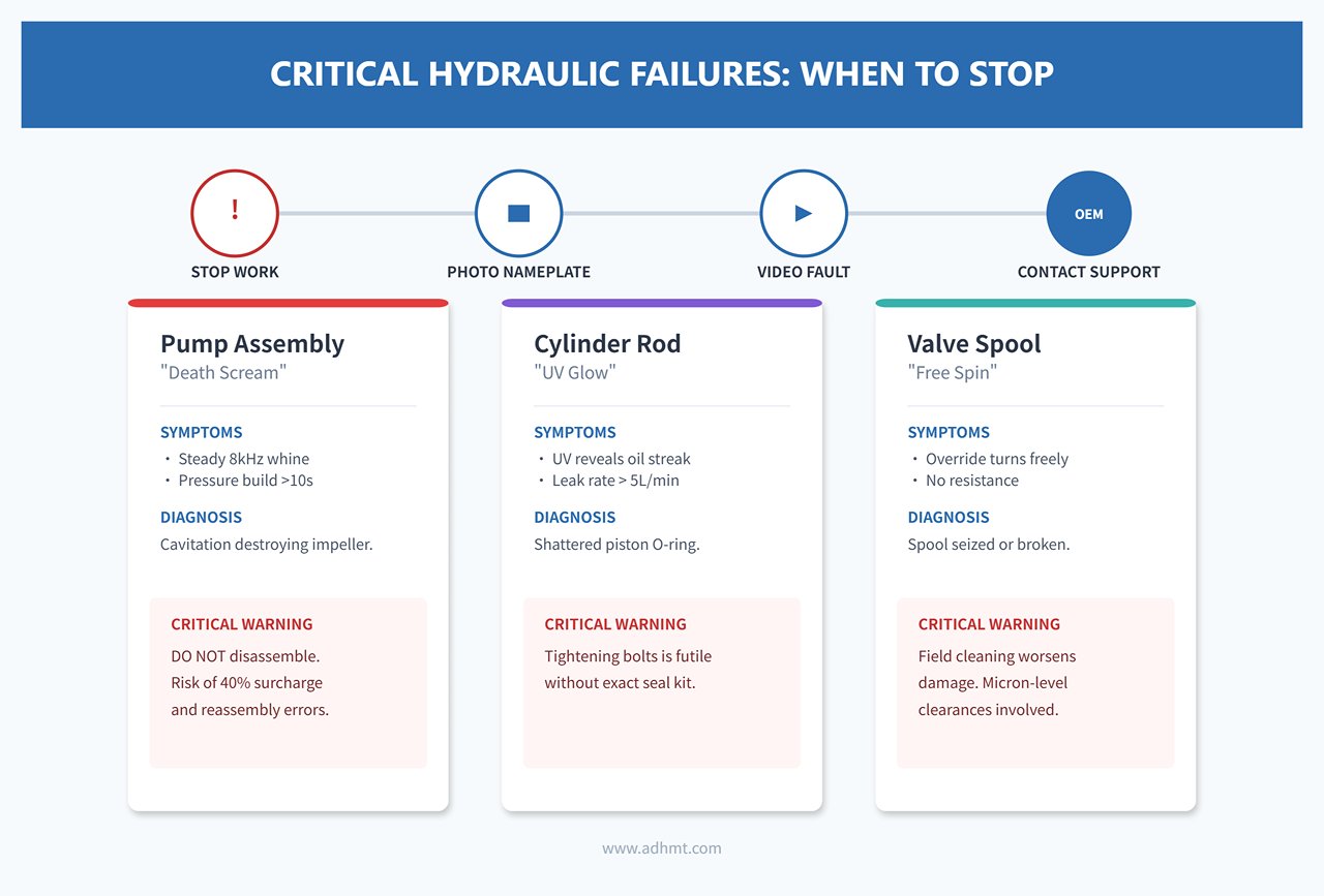
Action Protocol: If any symptom matches the above, immediately apply the “Record-Measure-Report” sequence—take photos, record sounds, measure dimensions, bundle the data, send it to the service provider, and tag the machine as out of operation.
“Degraded Production” Workaround: Safe Operation While Waiting for the Morning Shift
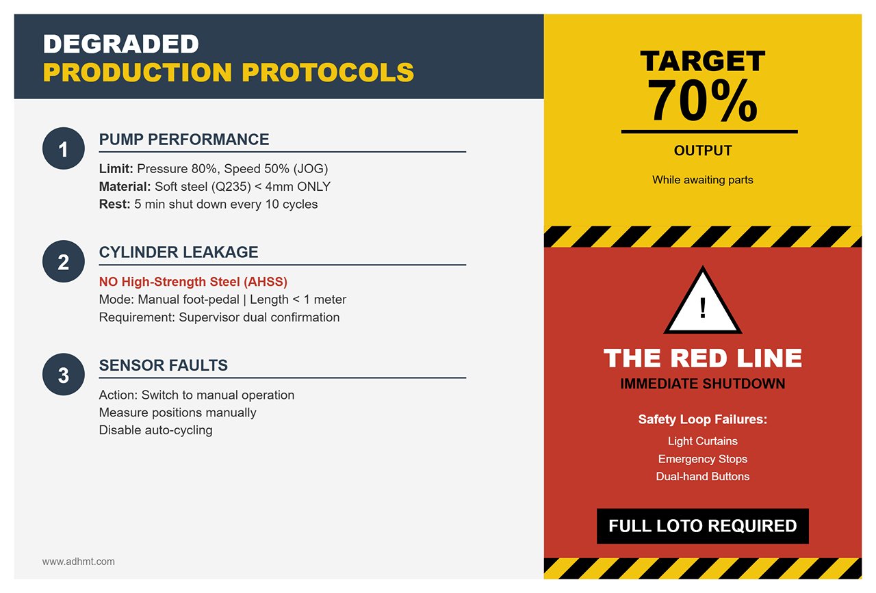
If the fault hasn’t crossed the red line and spare parts will only arrive with the morning delivery or technician, you can switch to a Degraded Mode. This approach trades efficiency for time—aiming to preserve 70% of night-shift output rather than restore full function.
- For declining pump performance: If minor wear is causing pressure loss, limit system pressure to 80% of the rated value and reduce shearing speed (JOG) to 50%. Only cut soft steel (Q235) under 4mm thickness and shut down after every 10 cycles for a 5-minute oil-tank cooldown. This prevents catastrophic impeller failure.
- For slight press cylinder leakage: If clamping force is weak, never shear high-strength steel (AHSS). Switch to the manual foot-pedal mode, ensure the clamp is fully engaged before triggering the cut, limit sheet length to under 1 meter, and assign a supervisor outside the safety fence for dual confirmation.
- For non-critical sensor faults: If the issue lies with non-safety limit switches (e.g., backstop counters), temporarily switch to manual operation, measure positions with a tape, and disable auto cycling. The red line is clear: any safety-loop failure involving light curtains, emergency stops, or dual-hand buttons requires full LOTO (Lockout/Tagout) and shutdown.
Write in the operation log: “Limited Operation 50% output Supervisor signature.” This note is your official protection when reporting to management in the morning.
The Final Decision: Work Overtime Tonight or Wait for the Morning Specialist
This is the most expensive equation of all. The hidden cost of a shearing machine downtime (contract penalties and production chain stoppage) usually ranges from $125K to $260K per hour. You must now compare the true cost of “tonight’s forced overtime repair” versus “waiting for the regular-day technician.”
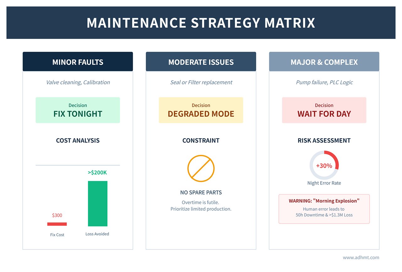
Use the following decision matrix:
Minor Faults (valve cleaning / sensor calibration):
- Decision: Fix it tonight.
- Reason: The overtime cost (around $300) is negligible compared with the overnight shutdown loss (>$200K).
Moderate Issues (seal or filter replacement required):
- Decision: Run in degraded mode.
- Reason: Without spare parts, overtime repair is futile. Maintain limited production until the parts arrive.
Major Repairs or Complex Issues (pump failure / PLC logic faults):
- Decision: Wait for the day shift.
- Reasoning: Data shows that diagnostic errors during late-night overtime shifts occur 30% more often than during regular daytime hours. Many technicians, hoping to save a few hours of downtime in the morning, push through the night to disassemble equipment—only to cause what we call a “Morning Explosion.” A reversed seal or a miswired cable turns a minor issue into a major failure, shutting operations down for 50 hours and costing over $1.3 million.
The insight that changes everything: The true mastery of maintenance isn’t just about fixing things—it’s about preventing further loss.
When you close the cabinet door and hang a tag reading “Under Maintenance” or “Limited Operation,” take a moment to recall the anxiety you felt at the start of this article. Back then, that shear machine seemed like an unfathomable black box—silent, unresponsive, and intimidating.
Now, you’ve learned to understand that silence.
You resisted the urge to tear things apart blindly. You didn’t take risks without spare parts on hand. And you didn’t push an exhausted team to create new problems in the middle of the night. Instead, you made a data-driven, professional decision.
Before ending your shift, review performance logs and compare them to maintenance procedures outlined for your Swing Beam Shearing Machine or Guillotine Shearing Machine. For further assistance or to schedule service calls, please contact us.
The first thing you should do: In the final line of the shift log, clearly document your decision logic—symptom, cost, and plan—then turn off the shop lights and leave with confidence.
Because you know that when the sun rises, there won’t be surprises here—only a recovery unfolding exactly as planned. That’s what real control looks like.


