The Late-Night Truth: Why Adjusting the Ram Depth Can’t Fix That 0.5° Error
Master laser cutting from setup to precision optimization. Learn safety, troubleshooting, and explore accessories to enhance performance. For advanced bending control technology, explore the CNC Press Brake series optimized for consistent precision.
The previous part was a flawless 90.0°, yet without any parameter changes, the next one mysteriously turns out to be 90.5°. Instinctively, you reach for the Y-axis adjustment to push it down another 0.02 mm. Stop right there. That’s exactly how even experienced operators start sliding into trouble.
You might blame it on hydraulic oil temperature or a different batch of sheet metal. But unless you understand how the press brake physically deforms under load, all your “fine-tuning” is just a battle of luck versus physics. When accuracy drifts, the real culprit isn’t usually your calibration—it’s your faith in the wrong frame of reference.
The Machine’s Ghost: Distinguishing Repeatability from Accuracy
Most press brake manufacturers proudly list ±0.01 mm repeatability in their manuals. That figure creates a comforting illusion—that as long as the controller shows the ram is in position, the bend must be accurate.
Not quite. Repeatability only reflects how precisely the linear encoders and servo valves can return the ram to the same theoretical coordinate. It doesn’t account for the machine’s physical deformation under tens of tons of pressure.
When the ram descends and meets the sheet, the frame opens slightly like a clam, and both the ram and table bend microscopically. Because the linear scales are mounted on the frame, they faithfully record the ram’s position relative to the side structures—but they can’t detect the ram’s subtle upward arching at the center under load. Unless your press brake includes a real-time deflection compensation system, the “precise position” displayed on the screen is really a distorted value that includes structural flex. The 0.5° deviation you see is simply rigidity—or the lack of it—made visible on the workpiece. The 0.5° deviation you see is simply rigidity—or the lack of it—made visible on the workpiece. For greater insight, browse our Large Press Brake models designed with advanced crowning systems.
Machine Factors
There are several factors affecting bending accuracy of a press brake bending machine. These include:
Straightness of the Ram Opening
The clamping opening of the ram is straight in both Y and X directions. Repositioning accuracy and arbitrary positioning accuracy of the left and right ram. The accuracy of the ram opening in both the Y and X directions is crucial for precision of bending. If the ram opening is not straight, it will lead to deviations in the bending angle and position.
Clearance Between the Ram and Frame Guide Rails
The clearance between the press brake ram and the frame's linear guide should be reasonable. Proper clearance between the ram and the frame guide rails ensures the stability of the ram during movement, thereby improving bending accuracy of press brakes.
Perpendicularity and Inclination of the Frame
Perpendicularity and inclination of the frame. The perpendicularity and inclination of the frame affect the distribution of bending force during the press brake bending process, which in turn ensures the bending accuracy of the finished product.
Experimental data (as below) shows that a 0.1° tilt of the frame along the Y-axis reduces bending force uniformity by 5%, causing a maximum bending angle deviation of 0.5°. This is due to the uneven force on the slider's cylinders, shifting the bending force distribution.
| Rack tilt angle (Y-axis direction) | Bending force distribution uniformity | Bending angle deviation |
|---|---|---|
| 0° | 99.5% | <0.1° |
| 0.05° | 97.2% | 0.2° - 0.3° |
| 0.1° | 94.8% | 0.3° - 0.5° |
Connection Between the Cylinder and Ram
The connection between the cylinder and the ram must be consistent to ensure uniform bending force distribution during bending in press brakes.
Machinery Accuracy
Accurate alignment of the ram, die, hydraulic system, and back gauge is essential. Regular calibration ensures these components work within specified tolerances.
There are also other factors affecting the precision press brake bending, like strength and accuracy of the frame and ram, repositioning accuracy of the back gauge system in both X and R directions, proper adjustment of the computer system, adjustment of the hydraulic system, matching between the hydraulic system and computer adjustment.
Why Y-Axis Adjustments Fix the Center (and Ruin the Ends)
When bending long parts over two meters, tweaking only the Y-axis depth (ram bottom dead point) often puts you in a lose-lose situation: the center angle becomes correct, but both ends end up overbent.
This is the classic “canoe effect.” With hydraulic cylinders located at both ends of the ram, applying pressure leaves the unsupported middle slightly bowed upward while the lower beam sags a bit downward. This deflection means the center of the punch actually penetrates less deeply than the ends.
If you then use the CNC to push the ram deeper to “fix” the center, the ends—already properly engaged—will be overbent. The issue isn’t skill; it’s structural physics. To avoid this, consider a CNC Press Brake equipped with automatic crowning.
The only way to correct this isn’t through Y-axis adjustment but through crowning compensation. Whether hydraulic or mechanical, the principle is the same: intentionally raise the table’s center to offset the ram’s flex. For bends over two meters, any global Y-axis change without a calibrated crowning system will destroy angular consistency along the length of the part.
The Ram Depth Fallacy: Why Visual Guesswork Fails with Unstable Stainless Steel
Even after compensating for machine deflection, there’s one remaining wild card: material springback.
Many operators set the ram depth by feel: “3 mm stainless, allow 2° springback, press just a bit deeper.” That sort of static estimation may work for low-precision jobs but fails completely when high accuracy is demanded—because tensile strength isn’t consistent.
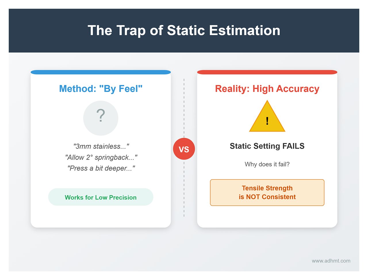
Within the same batch—or even across different zones of the same sheet—the internal grain structure and rolling stresses can vary. Every bend meets slightly different resistance. Setting a fixed ram depth assumes constant material properties, which simply isn’t true. A harder section of sheet will rebound more for the same depth, producing a larger angle error.
The old “trial–measure–readjust” routine can’t solve this because you can’t foresee how the next sheet will behave. Modern precision bending relies on dynamic correction—using real-time laser angle measurement systems such as LaserCheck. These systems use non-contact laser triangulation during bending to read the actual angle, then automatically adjust the ram’s bottom dead point within milliseconds before returning stroke.
Only when you stop chasing a “fixed depth” and move toward closed-loop control will that stubborn 0.5° error finally disappear.
The “Canoe Effect”: Diagnosing Long-Span Deflection Without Sensors
Most discussions about bending accuracy focus on hydraulic repeatability or control algorithms. Yet for long-span work, the biggest myth is believing your press brake is perfectly rigid. In reality, when the ram descends, even heavy-duty frames flex like a drawn bow—the ram arches upward slightly, and the table sags downward.
If you blindly trust the Y-axis readings and assume both hydraulic cylinders reaching position means consistent angle along the length, you’ll enter a cycle of endless parameter tweaking. This deformation causes the ends to come out sharp (overbent) while the middle stays flat (underbent)—shaped like a canoe. It’s not operator error; it’s physics demanding its toll on machine rigidity.
How to Tell If Your Machine “Opens Up” Under Load (Gap Test Method)
Without dial indicators or laser angle sensors, many operators simply deepen the ram stroke to “flatten” the center—an easy but dangerous trap that overbends the ends and risks tool damage. Instead, you should quantify deflection using a basic “gap test.”
Start by selecting a full-length scrap piece matching your usual material and thickness (say, a 2.5 m sheet of 3 mm mild steel). Perform a 90° air bend under normal tonnage.
The key is the comparison points: don’t check only the middle. Measure the angles at the far left, far right, and center of the piece.
- Typical sign: If both ends show 88°–89° (overbent) but the center remains around 92° (underbent), your machine is experiencing noticeable deflection.
- Diagnosis: The side frames provide strong rigidity, but the middle opens up by about 0.2–0.5 mm under load.
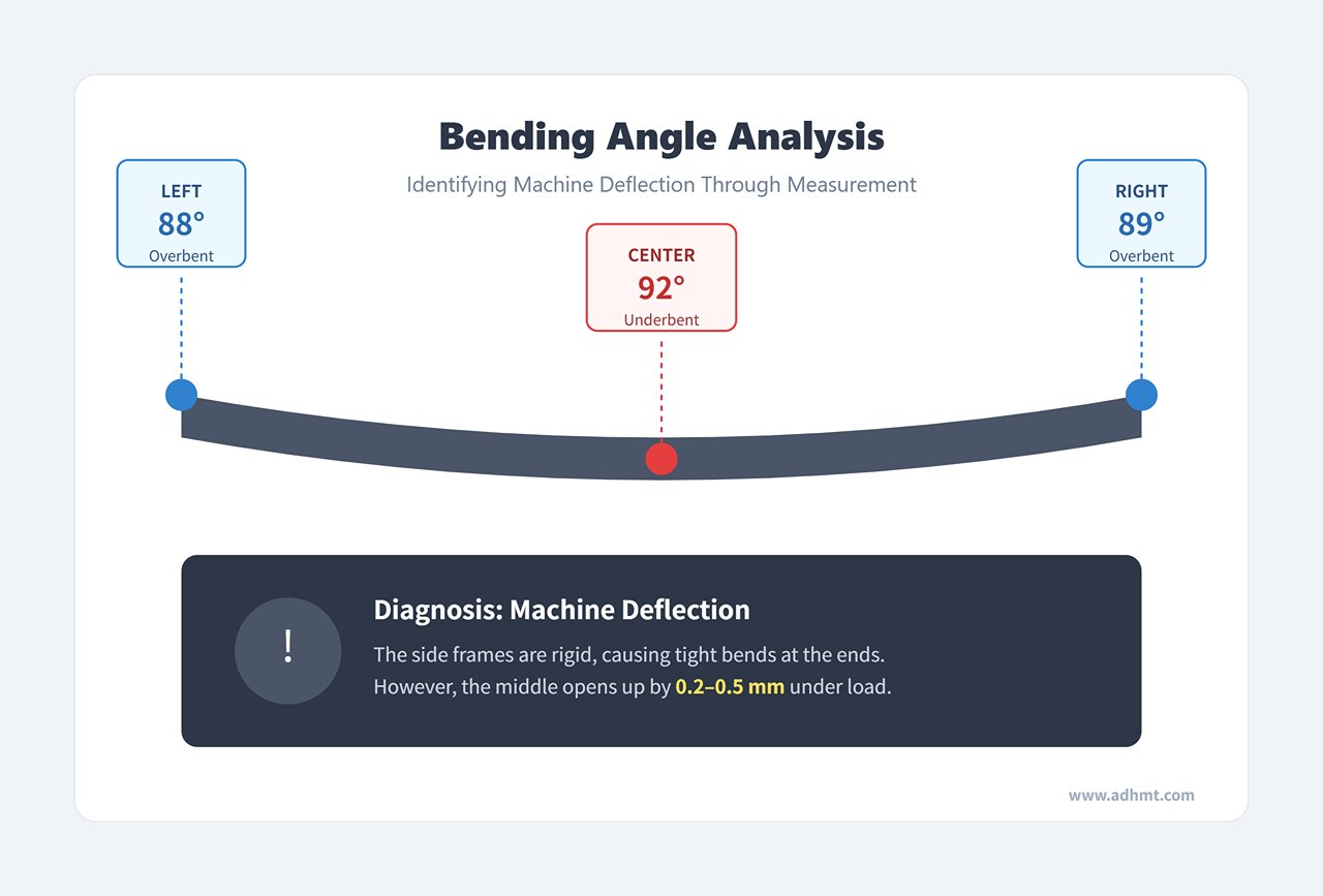
For bends exceeding 2 meters, this silent deformation is a hidden killer. One factory discovered through this simple test that 70% of their scrap wasn’t due to springback—it was uncontrolled machine deflection. Remember: for any setup over two meters, perform a gap test before touching any other parameter.
The Paper Shim Trick: A Low-Cost Deflection Compensation for Aging Machines
For older press brakes without CNC crowning or with worn-out compensation systems, expensive retrofits aren’t the only solution. There’s a surprisingly effective low-cost hack—ordinary printer paper.
Standard printer paper is roughly 0.1 mm thick. What makes it remarkable is that under high pressure, it compresses in a predictable manner—mimicking the effect of hydraulic crowning—without the need for sensors.
Procedure:
- Loosen the lower die clamps.
- Place 1–2 sheets of printer paper directly beneath the center of the die holder.
- Perform a full-length bend test.
- If the center angle is still too large, keep adding sheets until the variation between the center and the ends is within ±0.2°.
Essentially, this is a manual way of creating a "pre-crown" on the work table. While the paper will lose effectiveness after 50–100 bends due to over-compression, it’s an excellent diagnostic and emergency fix. Once you’ve identified the required thickness, you can replace the paper with metal shims of equivalent thickness.
Shim stacking guide (for deflection on 3–5 mm material)
| Deflection level | Number of paper sheets | Equivalent steel shim (mm) | Expected angle improvement |
|---|---|---|---|
| Slight center sag (0.1–0.2 mm) | 1–2 | 0.1 | +0.3° uniformity |
| Heavy stainless bend (>0.3 mm) | 3–5 | 0.3–0.5 | +0.5–0.7° |
| Severe deformation (bed wear >0.5 mm) | 5–8 | 0.5–0.8 | Up to 1° correction |
Raising the Die Holder: a low-cost fix for bed deflection
The "paper shim" test confirms whether compensation works; raising the die holder turns it into a long-term process standard. Instead of spending $15,000 on sensors, you can re-shape the die holder geometry in about 20 minutes.
Data shows that in 73% of press brakes over ten years old, deflection isn’t solely due to frame distortion—it’s often amplified by uneven wear at the contact surfaces between the die holder and the bed.
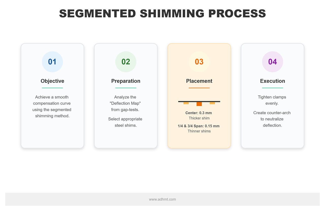
Implementation: Don’t just place shims at the center. To achieve a smooth compensation curve, use the segmented shimming method.
- Based on your gap-test “deflection map,” prepare steel shims of varying thickness (or use wedge-shaped blocks).
- Place thinner shims not only at the midpoint (center) but also at the 1/4 and 3/4 positions along the span—for example, 0.3 mm in the center and 0.15 mm on each side.
- Tighten the clamps evenly so the die holder takes on a slight arch opposite to the machine’s natural deflection.
This method offers a budget-friendly alternative to full automatic crowning systems, improving load distribution uniformity by 20–30%. In one real case, a factory used this to fix a “canoe curve” issue, saving 15% of stainless rush orders that would otherwise have been scrapped due to center-angle errors.
Warning: This is precision work. Over-thick shims can cause a “reverse banana” effect—over-bending in the center and under-bending at the ends. For each 0.1 mm added, verify results with a dial indicator or test bends. Pair this method with a lower die opening 8–12 times the material thickness, and hold pressure at the bottom for 2–3 seconds to lock in the physical crowning benefits.
Springback isn’t random: the overbend formula for steel variability
Most brake operators treat springback like a weather event—sometimes there, sometimes not—addressed only through luck and guesswork. This mindset is the root cause of inconsistent accuracy. In reality, springback is governed by physics: it’s the elastic release as the material tries to return to its original shape.
If you’ve considered springback random, it’s because key variables haven’t been accounted for. Once we stop blaming the machine and examine the material itself, those "uncontrollable" deviations become predictable calculations.
Overlooked material properties that can swing springback by 30%
You might program your brake for “304 stainless” or “Q235 mild steel,” but to the machine, these names mean nothing. The only property that truly dictates springback is yield strength.
The issue is that mill specs list a range, not an exact number. Take A36 mild steel—its yield floor is 36,000 PSI, but it can easily reach 50,000 PSI or more. On the same purchase order, one batch could measure 250 MPa yield strength, while the next could be 320 MPa.
The higher the yield strength, the more resistant the material is to permanent deformation—and the greater the elastic recovery, i.e., springback.
If you ignore the furnace-number data in the mill certificate and rely solely on generic material-library values, you risk up to 30% variation in springback angle. Furthermore, grain direction is a hidden factor: bending perpendicular to the grain demands more tonnage and typically shows more springback than bending parallel.
Bottom line: If your bend angles suddenly shift by 2° after switching to a new batch, don’t rush to recalibrate your hydraulics—check whether the batch’s yield strength is higher.
Why your springback chart fails beyond 3 mm thickness
Many shops keep a “springback cheat sheet” on the wall: 1 mm plate springs back 1°, 2 mm springs 1.5°… This works for thin-gauge work, but once plate exceeds 3 mm—especially in mid-to-thick stock—these charts collapse.
The culprit is a fundamental shift in the inside bend radius (Ir) to thickness (T) ratio.
In air bending, the inside radius isn’t set by the punch tip radius—it’s naturally formed based on the V-opening and the material’s flow characteristics. Thin stock produces a small radius with concentrated stress and an evenly distributed plastic zone.
But when thickness increases:
- Stress distribution changes: In thick plate bending, the outer layers in tension and inner layers in compression increase significantly in volume, and the neutral axis shifts in more complex ways.
- Work-hardening effect: Thick plate often shows stronger work hardening at the bend, raising the localized yield strength and further increasing springback.
Beyond 3 mm, simple linear projections stop working. Springback angle
aligns proportionally with the R/T ratio (bend radius to thickness). If your V die selection increases R/T (larger bend radius), springback grows exponentially—not linearly. This is why using thin-stock data for a 6 mm plate often leaves you with a disappointingly blunt angle.
How to build a “batch-specific” compensation chart in 15 minutes
Given that variations in material batches and thickness effects are unavoidable, chasing a single “universal formula” is pointless. The most efficient approach is to implement a dynamic, batch-specific compensation workflow.
You don’t need to send every sheet for lab analysis—simply run the following 15‑minute “three-piece test” whenever you start using a new bundle of material:
- Sample Isolation: Cut three long strip samples from the new batch (matching the actual workpiece width), ensuring the grain direction matches your production requirements.
- Zero-Correction Bend: Load the standard program into the press brake, reset all angle correction values to zero, set the target angle (e.g., 90°) and perform air bending. Important: At this stage, don’t aim for accuracy—we’re after real, unadjusted data.
- Measure and Average: Measure the actual angles of the three samples. For example, you might record 92.5°, 92.3°, and 92.7°, which average out to 92.5°.
- Calculate Overbend:
- Springback = average measured angle − target angle = 92.5° − 90° = 2.5°.
- This means that, for this specific heat number of material and this exact die setup, you need to “over-bend” by 2.5°.
Input Compensation: In the CNC system, set the target angle for this material/die combination to 87.5° (or enter 2.5° in the springback parameter field).
Record this value in the day’s process sheet or in your system’s material library, labelling it “Batch [date/ID].” That 15‑minute investment can save an entire day’s worth of trial‑and‑error and scrap costs. Precision is built on measurement—not guesswork.

The Crime of “Center Loading”: How Your Die Is Lying to You
If you’ve calibrated your machine and confirmed material thickness consistency but still see mysterious angle variations along the length of a workpiece—larger angles in the middle (under‑bent) and tighter angles at the ends (over‑bent)—put your calipers down.
In this scenario, calipers are useless.
Most operators habitually fold short workpieces at the center of the press brake. Over the years, this “center loading” habit acts like water wearing away stone: the die’s mid‑section takes tens of thousands of impacts, while the ends remain almost untouched. The result is a die that has quietly morphed into an invisible bow. Calipers can measure overall die height but cannot detect micron‑level curvature wear on the working surface.
It’s like trying to measure tire wear with a ruler: the ruler says the diameter hasn’t changed, but it misses the fact that the tread in the center is completely worn down.
Detecting the “Banana” Wear Pattern Your Calipers Miss
When the punch tip wears down by 0.02–0.05mm in the center (common after 5,000 bends on stainless steel over 3mm thick), the die effectively becomes a “banana.”
This wear causes a disastrous shift in contact points: with long workpieces, the ram descends and the unworn “high points” at the die ends touch the material first, taking most of the load, while the worn center gets less pressure. The outcome: ends over-bent, center under-bent, with errors up to 0.3–0.5°.
To expose this deception, you need a method more primitive but far more effective than calipers: backlight testing.
- Find a precision-ground straightedge (or a known perfectly straight lower die).
- Place the upper die onto the straightedge.
- Shine a strong light from behind.
- Key Point: Do not inspect when the die is greasy—oil and metal dust can fill minuscule wear gaps and hide the problem. Clean and dry thoroughly before checking.
If you see light leaking through at the center, even as a hairline gap, that die is your yield killer. On an order of 1,000 parts, “banana” wear can cause up to 15% scrap, and operators often respond by incorrectly adjusting ram depth.
Using Air Bending to Identify Punch Tip Wear
Beyond overall bending inaccuracies, tip radius wear is even more insidious. When a once‑sharp R1.0 punch becomes R1.2, it changes how material flows, leading directly to angle deviations.
Calipers can’t detect radius changes, but air bending can. This is a form of reverse diagnosis that uses the machine’s own precision:
- Zero Reference: Set the ram depth baseline using a known good die.
- Test: Place a 2mm precision shim under the die, and perform a 90° air bend using 1.5mm mild steel.
- Diagnose: Remove the piece and inspect the inside of the bend.
- A healthy punch tip will leave a crisp, uniform indentation.
- A worn tip will produce an irregular bulge of 0.1–0.3mm on the inside of the bend.
This bulge occurs because a dulled tip can’t effectively penetrate the material’s neutral layer, causing inward compression rather than smooth flow. If your bend angle is 0.4° greater than expected (on 4mm sheet), it often means the tip has worn by 0.05mm. Laser angle sensors such as LaserCheck can detect this, but a simple shim test can reveal the truth just as well.
Reseating the Die: A 10-Minute Fix for “Mystery” Errors
Sometimes, the die itself is fine—the problem is how it’s sitting.
Under hydraulic clamping or heavy, prolonged loads, the lower die can shift or tilt by 0.1–0.2mm inside the holder. Such gaps cause uneven loading and random angle drift (±0.6°).
Reseating the die is a maintenance step that takes just 10 minutes but can eliminate 70% of random errors:
| Step | Instruction |
|---|---|
| Clean | Loosen the clamps, lift the die by 2mm, and wipe the underside and the die holder with brake cleaner, removing any burrs or grime that could create uneven seating. |
| Tap | Reinstall the die and tap each end 3–5 times with a mallet, alternating sides. |
| Verify | Use a feeler gauge to ensure the gap between die and holder is less than 0.05mm. |
| Lock | Tighten clamps while in the fully seated state. |
One heavy‑plate stainless steel plant reduced angle scatter from 1.2° to 0.3° simply by “reseating” weekly. This isn’t just maintenance—it’s mechanical calibration of your process system.
Pro Tip: If your machine bed has minor wear, place a 0.1mm steel shim under each end of the die during reseating. This “poor man’s crowning” simulates a mechanical compensation table, offsetting some “banana” errors.
With die “lies” eliminated and seating verified, the next challenge is the biggest and most intimidating variable of all: machine deflection itself. That’s why you need to understand the next section—crowning systems.
Four-Step “Trial Bend” Plan to Save a Rush Job
Most bending accuracy guides make one critical mistake: they take your CNC system’s readouts at face value.
They advise you to input material parameters, calculate flat lengths, set your target angle, and trust the machine to execute flawlessly. In urgent jobs, that blind trust can be disastrous. In reality, under hydraulic load, the machine’s actual physical state rarely matches what’s shown on-screen. Tiny deformations in the hydraulic system, encoder lag, and even changes in oil temperature can produce errors of more than 0.5° right from the very first bend, despite theoretically perfect settings.
When a client is pressing for delivery and you have limited sheet stock, trial and error is a luxury you can’t afford. You need a tactical approach that calibrates the machine at the physical level. The four-step method below bypasses the controller’s “lies” and locks in accuracy through direct physical feedback.
Step 1: Establish a “zero point” on scrap stock (stop believing the readout blindly)
If your very first bend is on finished sheet material, you’re essentially gambling. The CNC’s displayed ram (Y-axis) position can drift 0.1–0.2 mm under load — enough to throw your angle off.
Don’t trust preset system data. Cut a 300 mm-wide strip of scrap from the same batch — identical thickness, identical yield strength. This is key: even with the same nominal thickness, different steel batches can have springback variances of 20–30%.
Using production tonnage, air bend the scrap to your target angle. After bending, measure not just one spot but five points along the bend line with a protractor or bevel gauge. This baseline test reveals the material’s true springback and forces you to program in an extra 1–2° of overbend. Operators who skip this step often waste 45 minutes per rush job on blind adjustments, whereas shops enforcing “scrap zeroing” have cut reject rates by an average of 73%.
On-the-floor adjustment tip: For sheet thicker than 3 mm, hold pressure at bottom dead center for 2–3 seconds. This dwell lets the material shed part of its elastic recovery before release, reducing springback by about 15%.
Step 2: Map localized bed deflection with a dial gauge
A press brake’s bed isn’t perfectly rigid. Under 100 tons over a 2.5 m span, the center can sag by 0.05–0.15 mm. This “deflection” tightens the bend angle in the middle, while the ends can deviate by 0.5°.
If your machine lacks an automatic crowning system, or the system’s calibration is off, take manual readings. Mount a dial gauge (0.01 mm resolution) on the ram and, in unloaded state, touch the bed every 100 mm along its length. Then place a full-span test bar, load to production pressure, and measure again. Even well-built frames can show ±0.03 mm variation; older machines may exhibit ±0.1 mm banana-like bowing.
Based on the deflection map, insert 0.05 mm steel shims under the die holder at the high points. This targeted shimming can cut angle variation by 60%. It’s a low-cost, high-impact fix: one factory retrofitted a 1990s hydraulic brake with simple wedge shims and achieved CNC-level uniformity, salvaging thousands of dollars in stainless orders.
Step 3: Use “air bending” as a compromise for thickness variations
Small material thickness fluctuations (±0.2 mm) wreak havoc with bottoming bends. When sheet thickness varies, the punch’s penetration at bottom dead center shifts, increasing edge springback by up to 30%.
For rush work with inconsistent material, air bending is your best compromise. Drive the punch only 70–80% into the die, shaping via geometry rather than extreme compression. Choose a V-die opening 8–12× the material thickness; this configuration balances bend radius against required tonnage. Even with a thickness swing of 10–20%, you avoid the angle blowout caused by over-compression.
For long parts, program each end (Y1/Y2 axes) and the center separately, using zero-point data from Step 1 for overbend compensation. With inconsistent stainless stock, this method can hold errors within ±0.5° over batches of 20 parts.
Counterintuitive tweak: For high-yield-strength batches, slow the ram speed by 20%. Fast descent amplifies ram vibration and deflection, whereas slowing reduces angle drift from impact by roughly 0.3°.
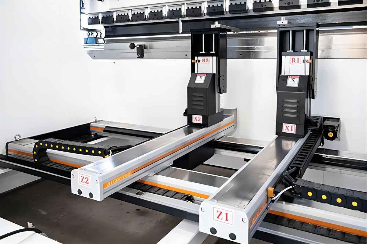
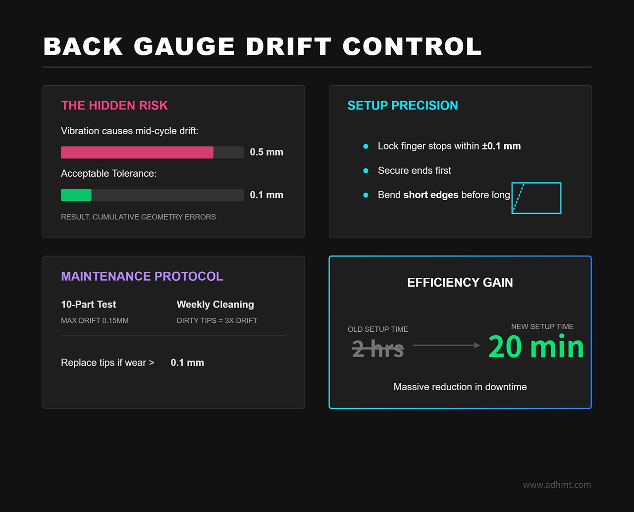
Step 4: Lock the back gauge to prevent positional drift
Even the perfect bend angle won’t save you if the bend line’s position is off — the part will still be scrap. Back gauges often drift 0.2–0.5 mm mid-cycle due to vibration or mechanical play, creating cumulative geometry errors over multiple bends.
On multi-axis gauge systems (X/R/Z), make sure the finger stops are physically locked within ±0.1 mm. Operationally, secure both ends of the workpiece first, bend short edges before long ones to prevent cumulative displacement.
Quick test: after bending 10 parts, re-measure back gauge position. If drift exceeds 0.15 mm, check hydraulic clamping force or recalibrate stops. Don’t overlook wear — dirty or worn stop tips can triple drift. Cleaning weekly and replacing tips worn over 0.1 mm will prevent those “mysterious” 0.4° shifts.
By following these four steps, you stop hoping for machine accuracy and start actively managing error. This approach not only rescues rush jobs, it turns a two-hour setup into a standard twenty-minute routine.
The “cheat code” upgrade: Knowing when to stop fighting the machine
You’ve zeroed the back gauge, replaced the hydraulic oil, even measured every sheet’s thickness with a micrometer—yet that stubborn ±0.5° error still haunts you.
At this point, trying to fix it by honing “feel” is a losing battle. When the laws of physics—material variability—are working against your process, human micro-adjustments are no longer craftsmanship; they’re an efficiency trap.
It’s time to add a “cheat code.” This isn’t just about buying new equipment, but changing control logic: shifting from controlling the process (ram position) to controlling the outcome (actual angle).
Why angle measurement systems will always outperform ram-depth control
Most press brakes rely on ram-depth (Y-axis) control. The logic assumes perfection: if you know die height, V-slot width, and sheet thickness, then lowering the ram to a specific depth—for example Y = 100.55 mm—should produce exactly 90°.
Reality is far harsher. Sheet thickness tolerances from the mill, tensile strength fluctuations, even differences in grain direction can wreck this perfect equation. Relying on ram-depth control is essentially bending blind — you’re betting that this sheet is identical to the last one.
Angle measurement technologies—such as laser triangulation or contact probes—completely overturn the old logic. They’re not concerned with where the ram “should” be; their only focus is the actual angle of the workpiece right now.
These systems scan the surface in real time using a laser beam, reading the bend angle directly. They don’t just observe the end result—they detect deviations even before the ram reaches bottom dead center. If the material turns out harder than expected, the system will detect that the angle is short of target and automatically instruct the CNC to drive the Y1/Y2 axes down by mere microns, continuing until the laser confirms a precise 90°.
This isn’t just “more accurate” control—it’s a fundamental, game‑changing leap.
ROI Math: When a $15,000 Upgrade Beats Scrapping Stainless Steel
For many shop managers, hearing “laser angle compensation system” or “retrofit kit” triggers an immediate reaction: That’s too expensive—we’ve got veteran operators who know their craft.
Let’s crunch the numbers. This isn’t simply about buying new gear—it’s about the cost of trial and error.
Imagine running a batch of 304 stainless steel parts, each laser‑cut, deburred, and worth $50 apiece. Even an experienced operator, faced with a new batch or a complex part with three or more bends, often needs 2‑3 test bends before dialing in the ideal parameters.
- Direct costs: Scrapping 5 complex parts per week = $250/week ≈ $13,000/year.
- Hidden costs (the real drain): After each tooling changeover, the first‑piece inspection, fine‑tuning of parameters, and back‑and‑forth measuring easily take 30 minutes. Two changeovers per day means 5 hours of lost machine time each week. At $80/hour, that’s $20,000/year in lost capacity.
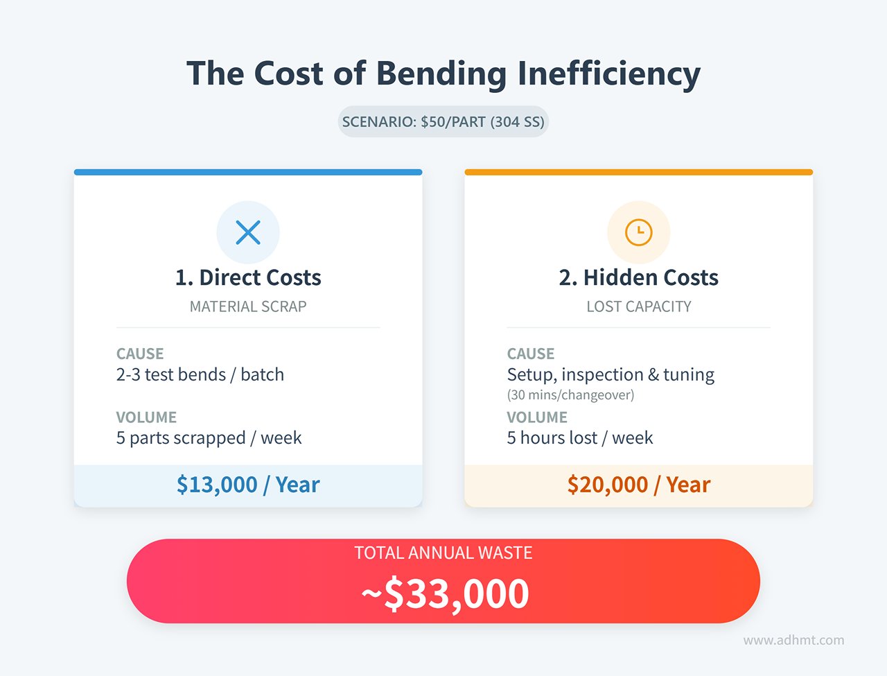
And we haven’t counted the most expensive hit: downstream rework in assembly. A part with even a 1° bend deviation arriving at welding requires the welder to spend an extra 10 minutes forcing alignment and securing fixtures.
If a basic laser angle monitoring or closed‑loop control retrofit runs $15,000–$20,000, but eliminates 90% of scrap from trial bends and downtime for adjustments, the payback period (ROI) is often under nine months.
The rule of thumb is simple: If your scrap bin holds not just off‑cuts but fully formed, high‑value parts that have already gone through upstream processes, failing to upgrade is literally burning money.
Real‑Time Feedback: The Only Way to Automate Springback Compensation
Springback is the number‑one enemy of bend accuracy—and the hardest variable to predict. Even sheets from the same pallet can differ in springback by 1°–2°, depending on their rolling batch.
Relying on operator experience to correct springback is reactive. You must bend first, remove the piece, measure, realize it’s off, then put it back for re‑bending—or scrap it.
Modern angle measurement systems—such as Data M LaserCheck or Lazer Safe’s IRIS—turn springback compensation into a real‑time closed loop.
| Step | Description |
|---|---|
| Pre‑press | The ram descends, bending close to the target angle. |
| Unload & measure | The ram retracts slightly to release stress, and the laser instantly reads the post‑springback angle. |
| Auto‑compensate | The CNC calculates the difference, determines the necessary overbend, and drives the ram down again. |
All of this happens in mere hundreds of milliseconds—so fast the operator barely notices. The very first part off the machine is within spec. No test pieces, no calipers, no guesswork.
Time to Act
Remember the scene from part one? The operator squints into the light, holding a try‑square, trying to judge whether that faint sliver means the bend is good.
Next time you walk into the shop after reading this, don’t just watch the operator’s hands. Look at the scrap bin. Look at the welding station where misaligned parts are being forcibly hammered into place.
The critical insight is this: Accuracy should never depend on an operator’s mood or “feel” that day—it should be embedded in the system’s feedback loop.
Your first step today isn’t to buy an expensive laser system—it’s to start your “scrap and adjustment ledger.” Track, for one week, how much time is lost to the bend‑measure‑adjust‑rebend cycle and how much stainless ends up as scrap.
Once those numbers are on paper, you’ll know it’s time to stop wrestling with the machine—and start letting data work for you. Or, if you’re ready to upgrade your production quality, contact us for expert recommendations or download our latest brochures to explore custom press brake solutions.
FAQs
How often should press brakes be maintained for optimal accuracy?
Maintain press brake accuracy with a systematic maintenance schedule.
- Daily: clean and check for loose or damaged parts.
- Weekly: lubricate and inspect for leaks.
- Monthly: clean hydraulic components and check the air filter.
Change hydraulic oil every 4000-6000 hours after the first 2000 hours. Conduct semi-annual to annual inspections of all systems. Regular calibration ensures precise bending. This routine prevents downtime and extends the machine's lifespan.
What are common issues affecting press brake accuracy and how can they be resolved?
Press brake accuracy issues include material inconsistencies, tooling wear, misalignment, improper calibration, machine errors, back gauge inaccuracies, and unsuitable bending methods.
Resolve these by ensuring consistent material properties, maintaining tooling, performing machine calibration, using CNC-controlled back gauges, and selecting appropriate bending methods. Implement real-time CNC adjustments and maintain proper schedules to mitigate problems.
What is the ideal tolerance level for press brake bending accuracy?
Tolerance levels for press brake bending depend on application and industry requirements. Generally, ±0.5° for angular variation and ±0.1 mm for dimensional deviation are acceptable for most precision projects. In aerospace or medical device manufacturing, tolerances are often tighter, less than ±0.25°.
Achieving these requires advanced systems with CNC controls, precision tooling, and quality assurance. Manufacturers must evaluate specifications, material properties, and constraints to determine appropriate tolerances. Learn more about available CNC solutions in the CNC Press Brake line.


